bench assembly instructions for saw cut axis

Difficulté
Difficile
Durée
2.5 heure(s)
Sommaire
- 1 Introduction
- 2 Étape 1 - Unless otherwise stated
- 3 Étape 2 - Check upstroke plate
- 4 Étape 3 - Assemble cut strip assembly
- 5 Étape 4 - Assemble cylinder
- 6 Étape 5 - Fit bearings
- 7 Étape 6 - Assemble cylinder mount bearing block
- 8 Étape 7 - Assemble bearing blocks
- 9 Étape 8 - Mount Bearing blocks
- 10 Étape 9 - Assemble rear grease line
- 11 Étape 10 - Add front grease line
- 12 Étape 11 - Important Check
- 13 Étape 12 - Assemble tensioner pulley
- 14 Étape 13 - Mount pulley to adjuster bar and motor plate
- 15 Commentaires
Introduction
Tools Required
Standard Hex key set
Standard spanner set
Internal circlip pliers
Consumable 4mm yellow grease line
Pneumatic pipe cutters
Parts Required
B0000002 Bearing: 12/28dia x 8mm Sheilded x 2
B0000032 Linear Bearing: Ø30 x 50 Compact (Metal Case Only) x 4
B0001061 Grease fitting x 6
D0004001 Head Bearing Block x 3
D0004021 Upstroke Plate x 1
D0004078 Motor Plate (5311) x 1
D0004099 Cylinder Bearing Block x 1
D0004256 Cylinder rod bar x 1
D0004343 Lower Damper Bracket (5313) x 1
D0004445 Semi circular slit strip (5533) 500mm x 1
D0004634 Chute Sawblade Strip 500mm (5532) x 1
D0004733 Belt Adjuster Pulley x 1
D0004734 Belt Adjusting Bar x 1
D0004735 Belt Adjuster Pin x 1
D0010780 Grease Manifold x 1
H0004444 Semi-circular Guard (5332) x1
P0000009 Fitting: 1/4 BSPT - 6mm Elbow x 2
P0000037 Magnetic Cylinder 40 x 185 with 15mm rod extension x 1
P0000308 Flow Controller In Line 6mm x 1
Étape 1 - Unless otherwise stated
All bolts to have Loctite 243 adhesive applied unless otherwise stated
All Threaded Pneumatic connections to have Loctite 570 applied
All bolts to be pen marked once adhesive applied and correct tension added

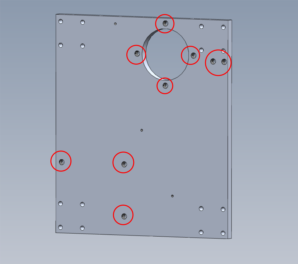
Étape 2 - Check upstroke plate
Check upstroke plate has helicoils fitted in indicated holes.
M8 thread will be present if they have, thread will be larger than M8 if they havent
Use workshop helicoil kit and add M8 x 1.5 od helicoils if not present

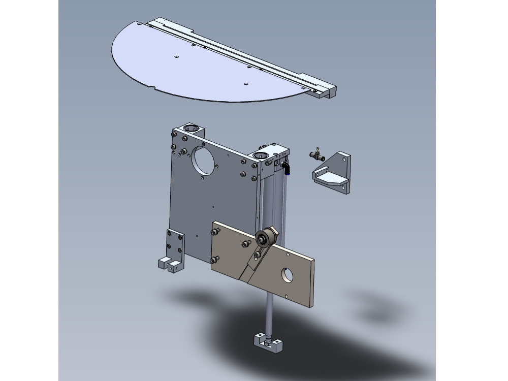
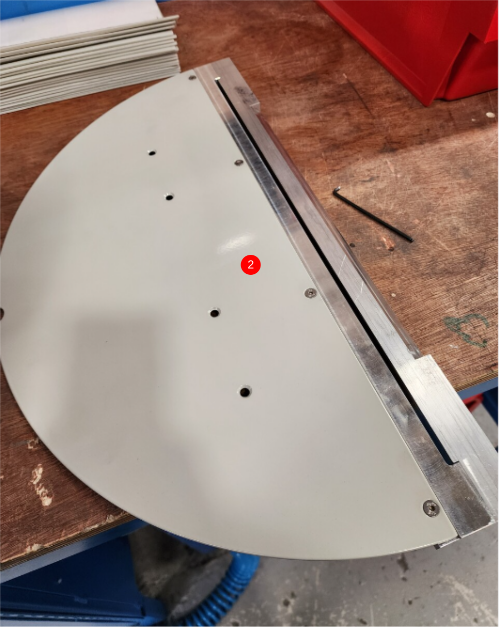
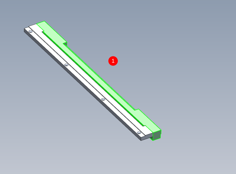
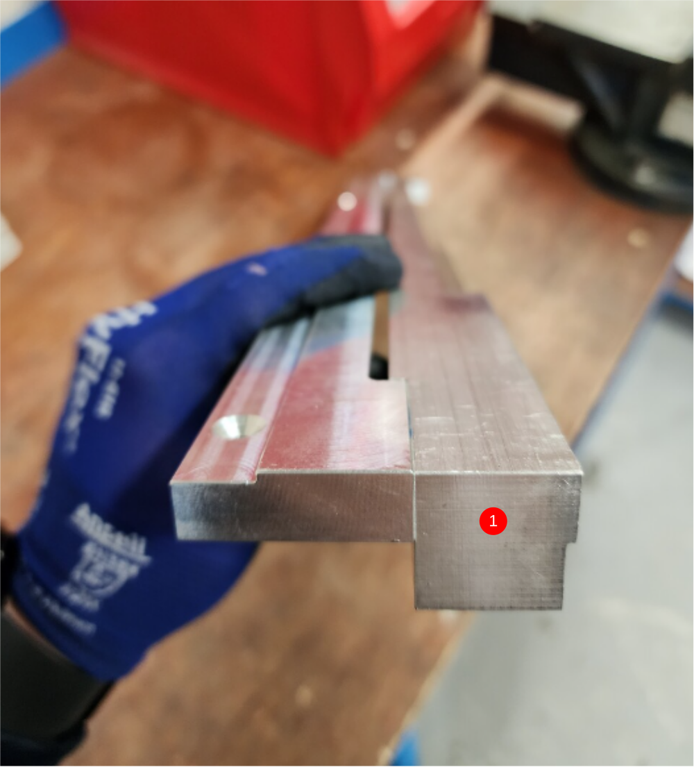
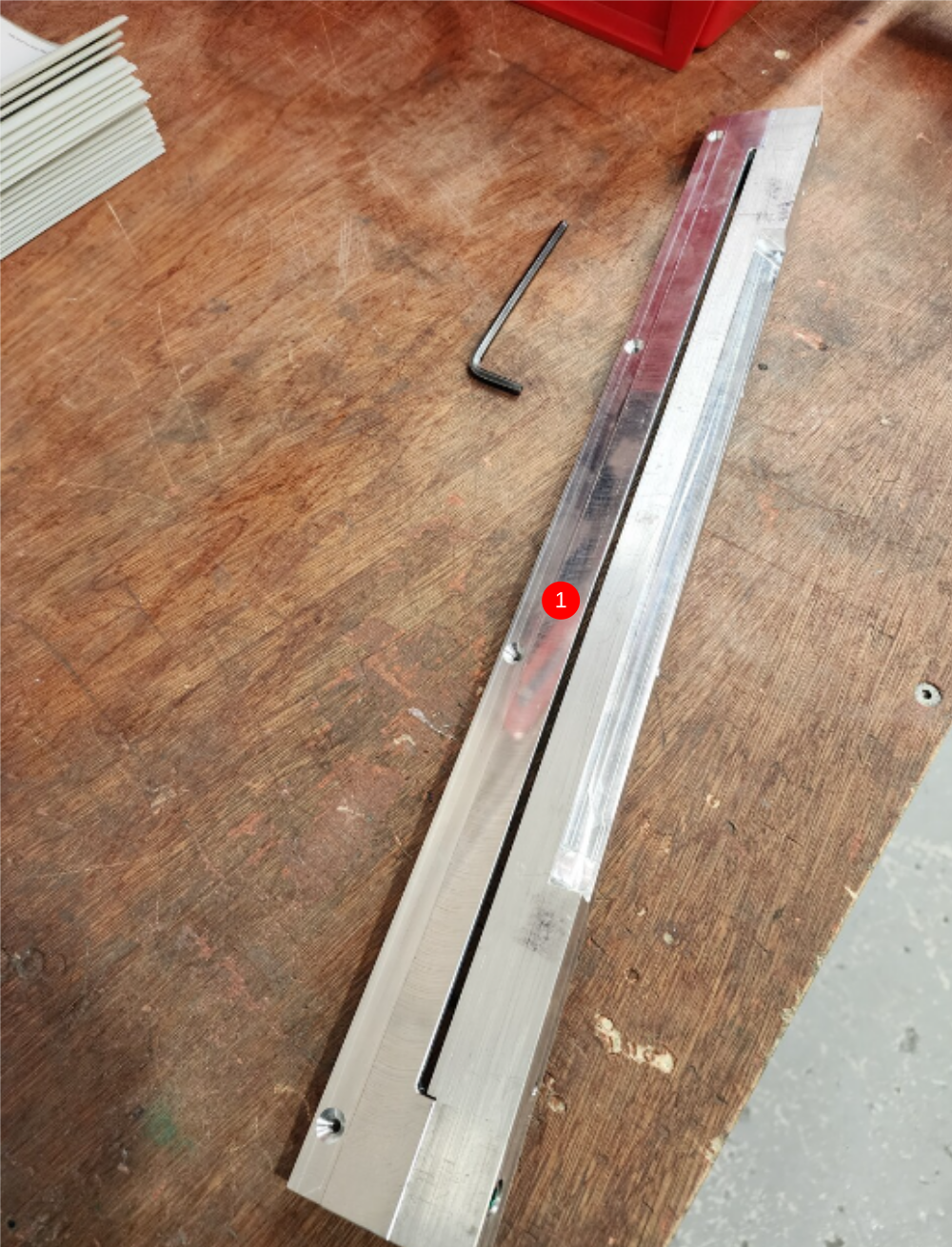
Étape 3 - Assemble cut strip assembly
1 Assemble D0004445 Semi circular slit strip onto D0004634 Chute Sawblade Strip as shown using 2 of M6 x 30 socket caps. Ensure all edges of parts are aligned flush when assembled
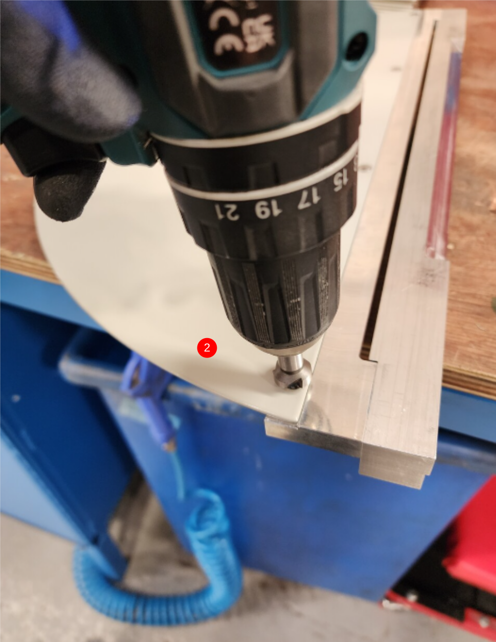
2 Fit H0004444 Semi-circular Guard as shown using 4 off M5 x 10 countersunk bolts. Ensure countersunk bolts sit flush when fitted. Adjust with countersink tool if sitting proud when fitted

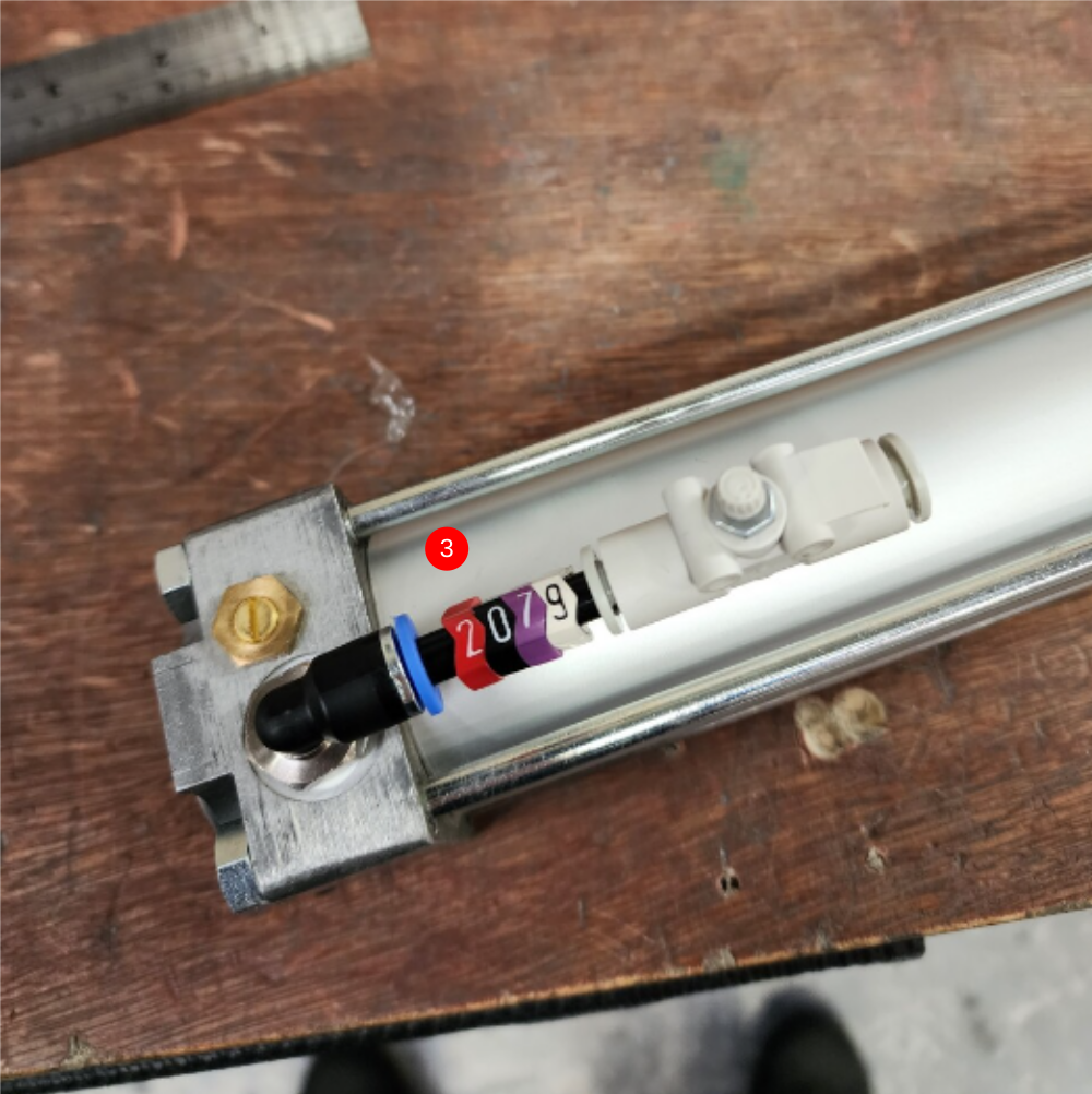
Étape 4 - Assemble cylinder
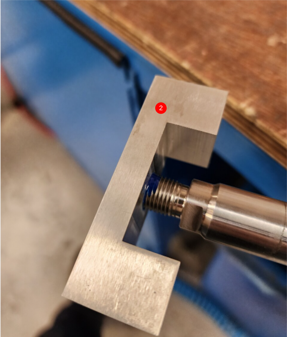
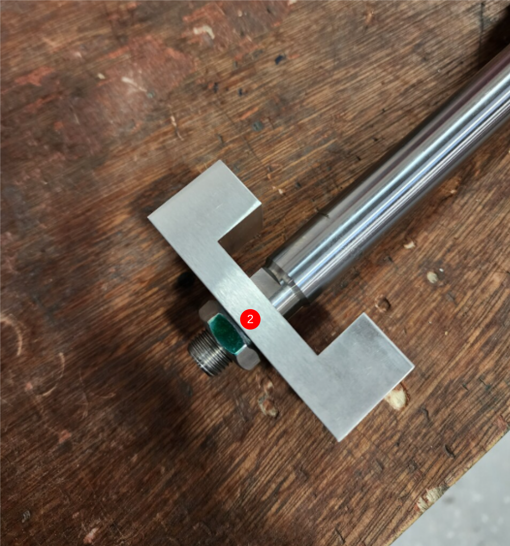
1 Attach 2 off P0000009 Fitting as shown
2 Attach D0004256 Cylinder rod bar as shown, and finalise lock nut
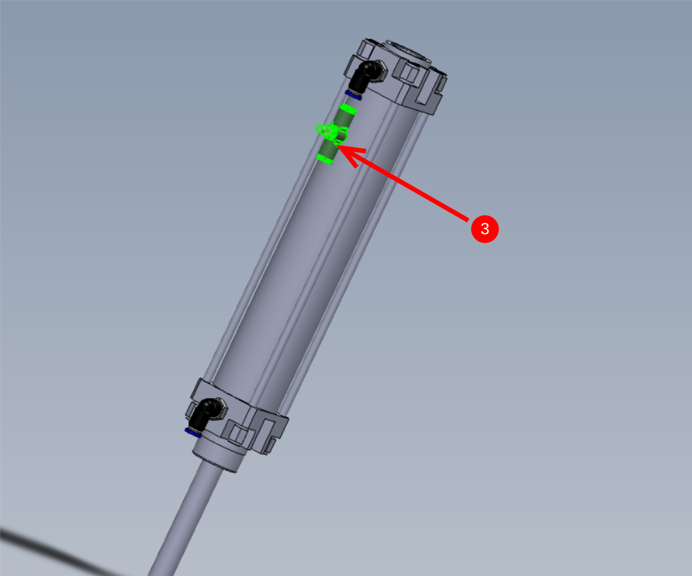
3 Attach P0000308 Flow Controller In Line 6mm to indicated fitting and connect with a 50mm long piece of 6mm black air pipe labelled as 2079


Étape 5 - Fit bearings
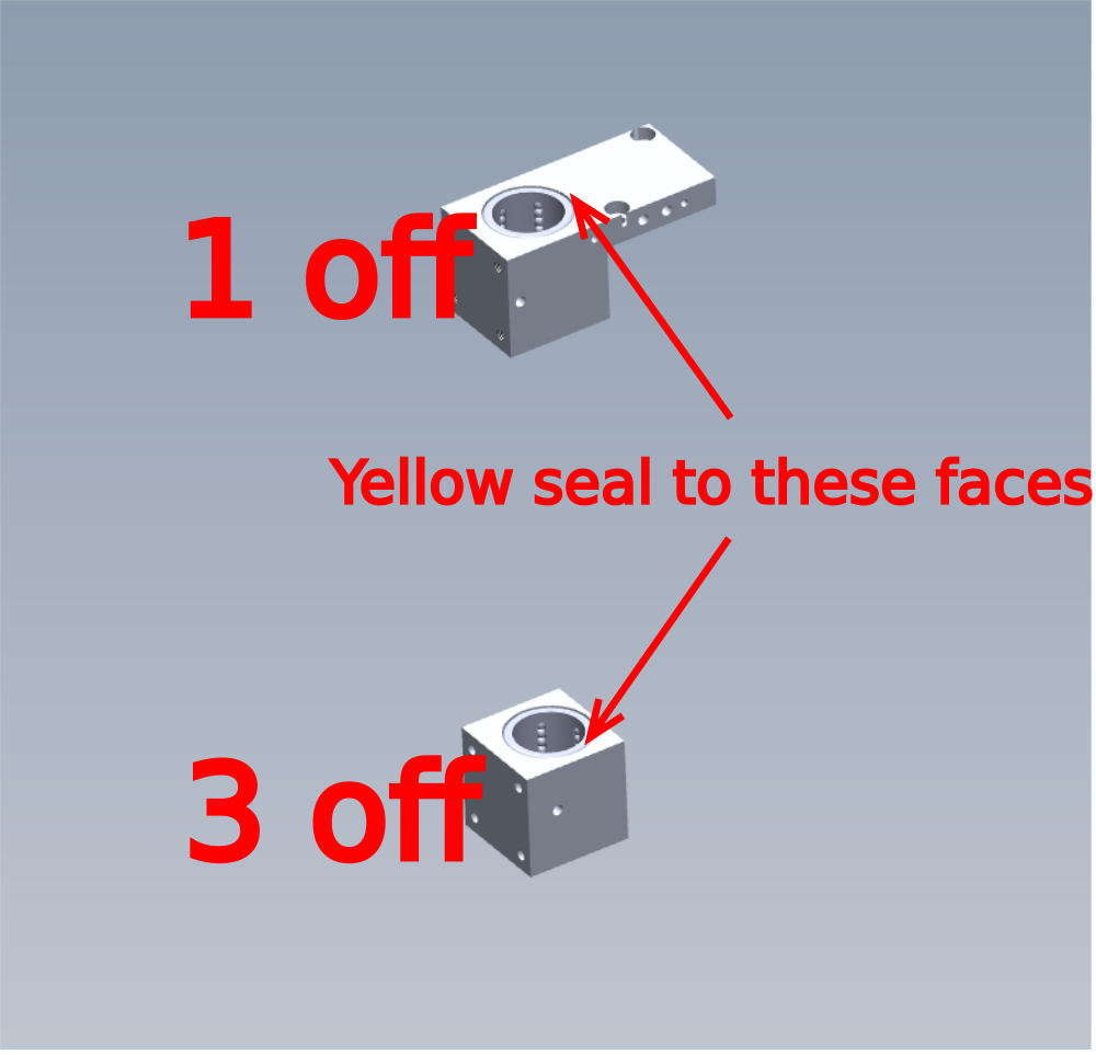
1 Degrease D0004099 Cylinder Bearing Block and fit 1 off B0000032 Linear Bearing. Ensure yellow seal of bearing is on indicated face
2 Fit B0000032 Linear Bearing with yellow seal to indicated face of Degreased D0004001 Head Bearing Block


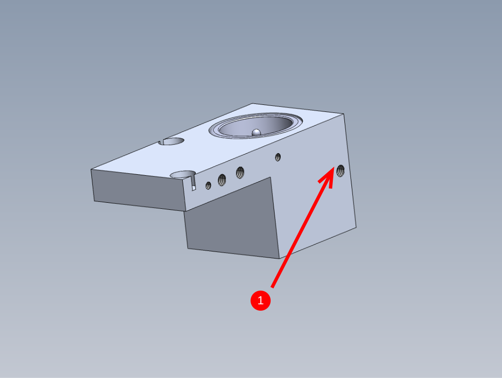
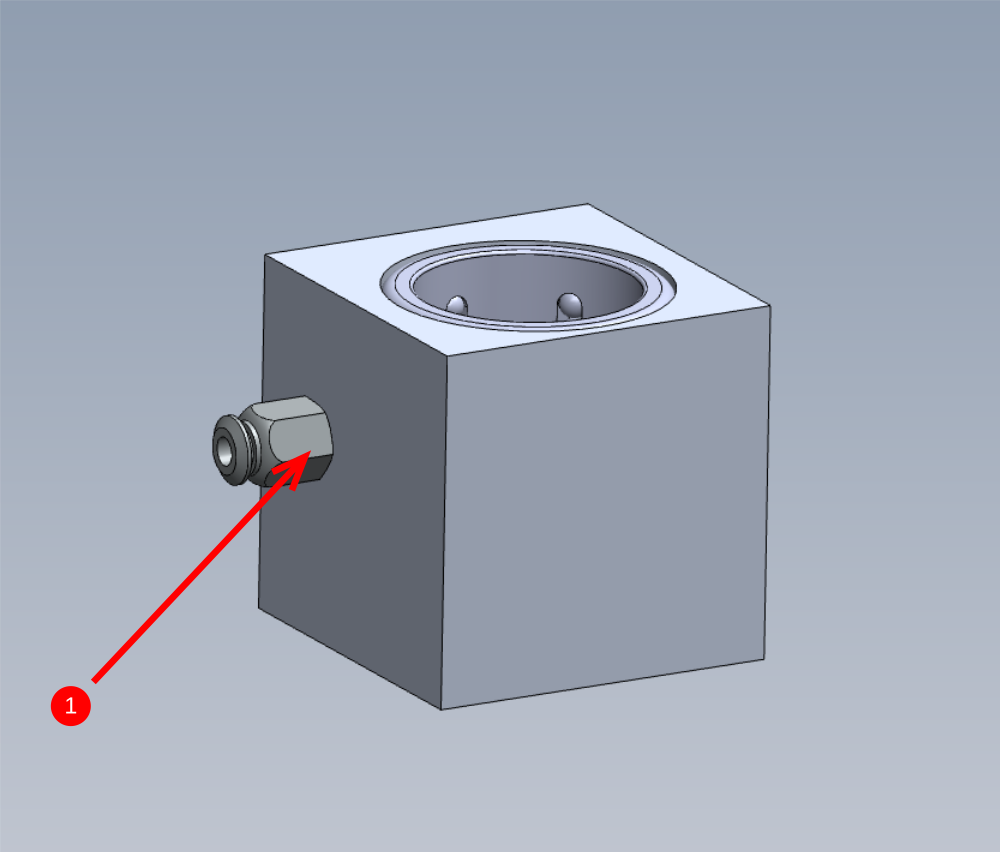
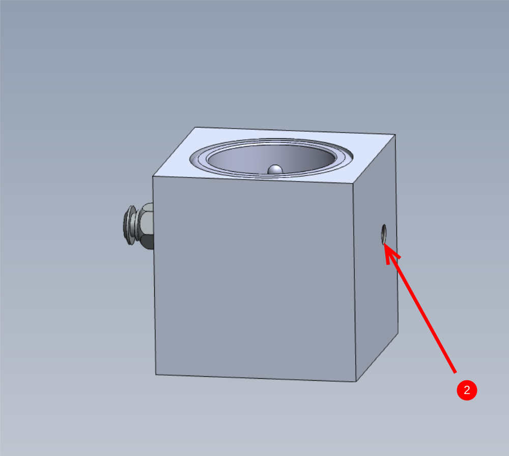
Étape 6 - Assemble cylinder mount bearing block
1 Add M6 x 6 grubscrew to indicated hole and secure with Loctite 572
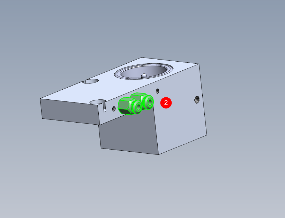
2 Fit 2 off B0001061 Grease fitting to indicated points
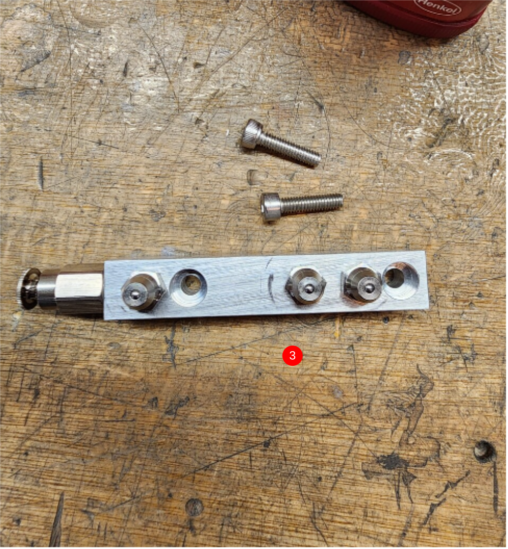
3 Assemble D0010780 Grease Manifold as shown using 1 off B0001061 grease fitting and 3 off B0000234 grease nipples (consumable stock) Use loctite 572 on threads
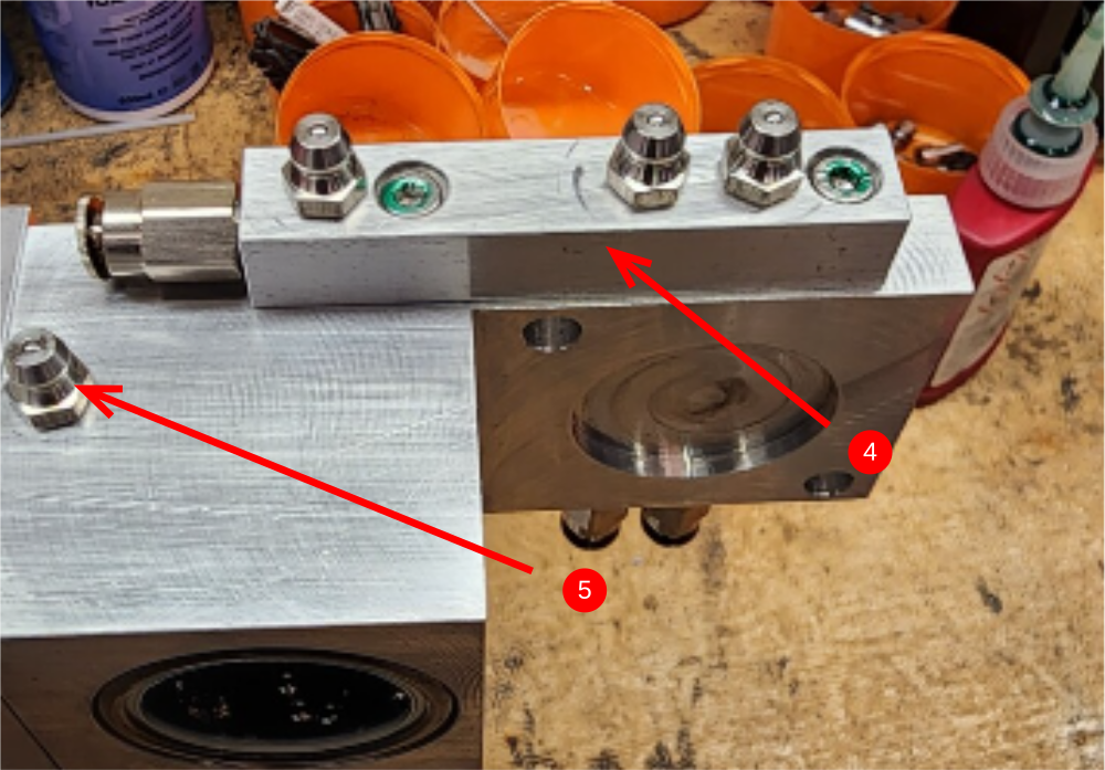
4 Fit to bearing block using 2 off M4 x 16 socket caps
5 Fit 1 off B0000234 grease nipple to indicated point

Étape 7 - Assemble bearing blocks
1 Fit B0001061 grease fitting to indicated face using Loctite 572 on threads
2 Fit M6 x 6 blanking grubscrew to indicated face using Loctite 572
Assemble 3 off in total as above

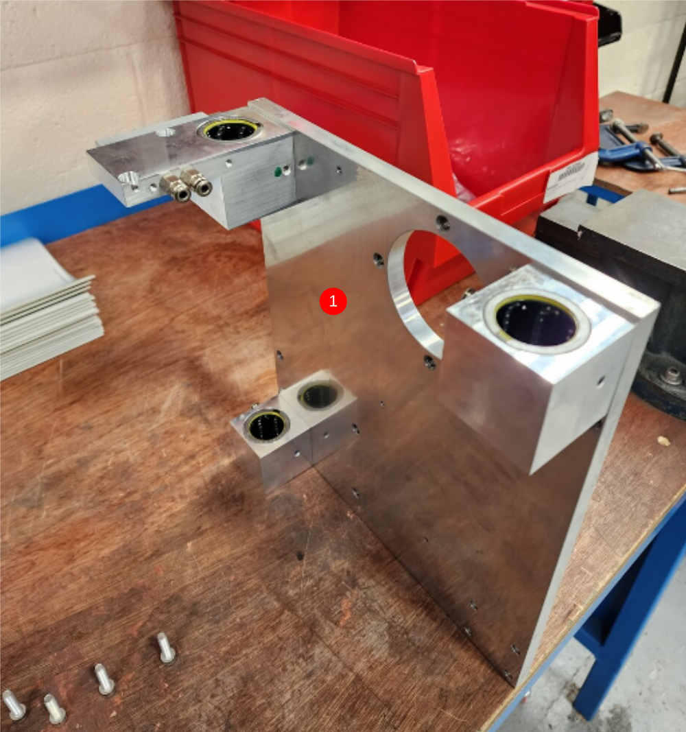
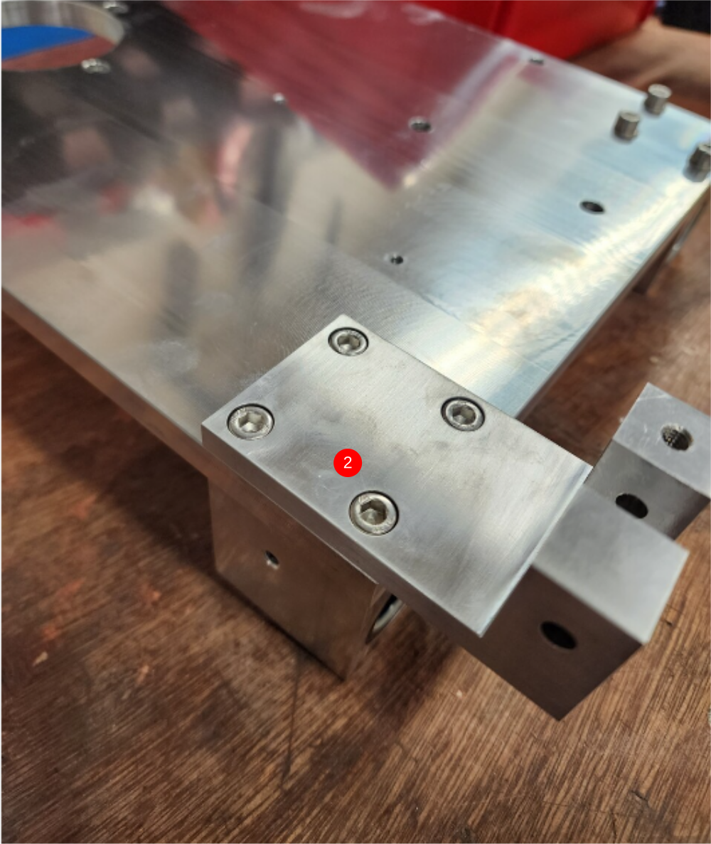
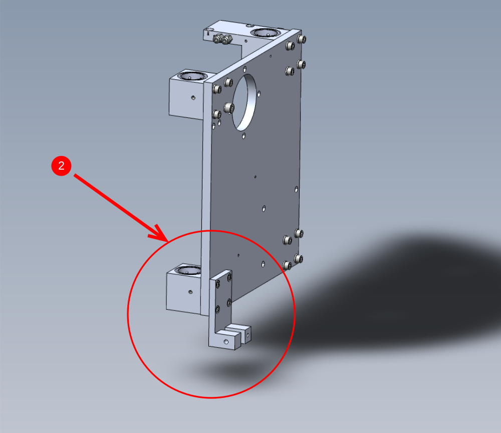
Étape 8 - Mount Bearing blocks
1 Mount cylinder bearing block and 2 off bearing block as indicated to D0004021 Upstroke Plate. Lightly secure with M6 x 25 socket caps and A form washers . Do not apply adhesive
2 Mount remaining bearing block as shown, incorporating D0004343 Lower Damper Bracket as shown . Use M6 x 25 socket caps, again do not apply adhesive or apply final tension

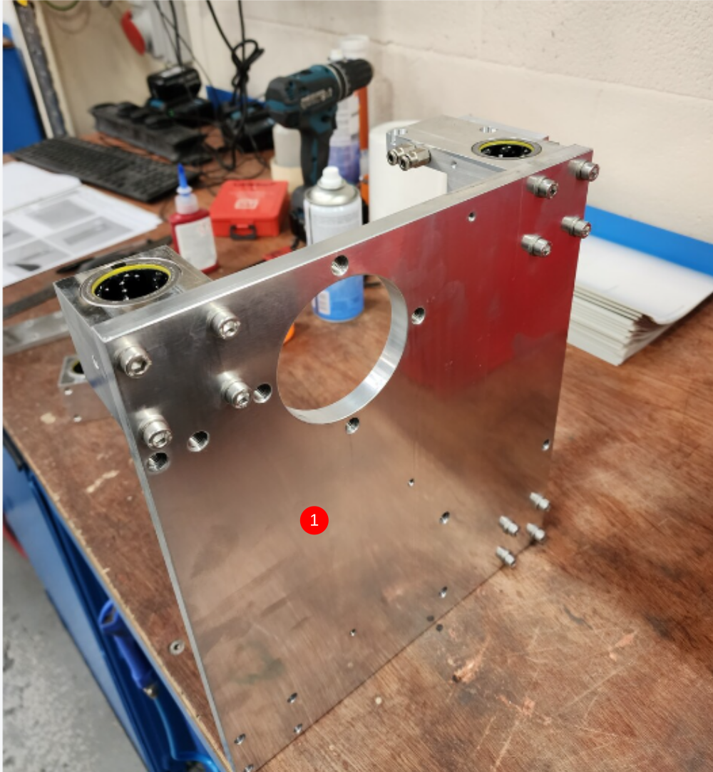

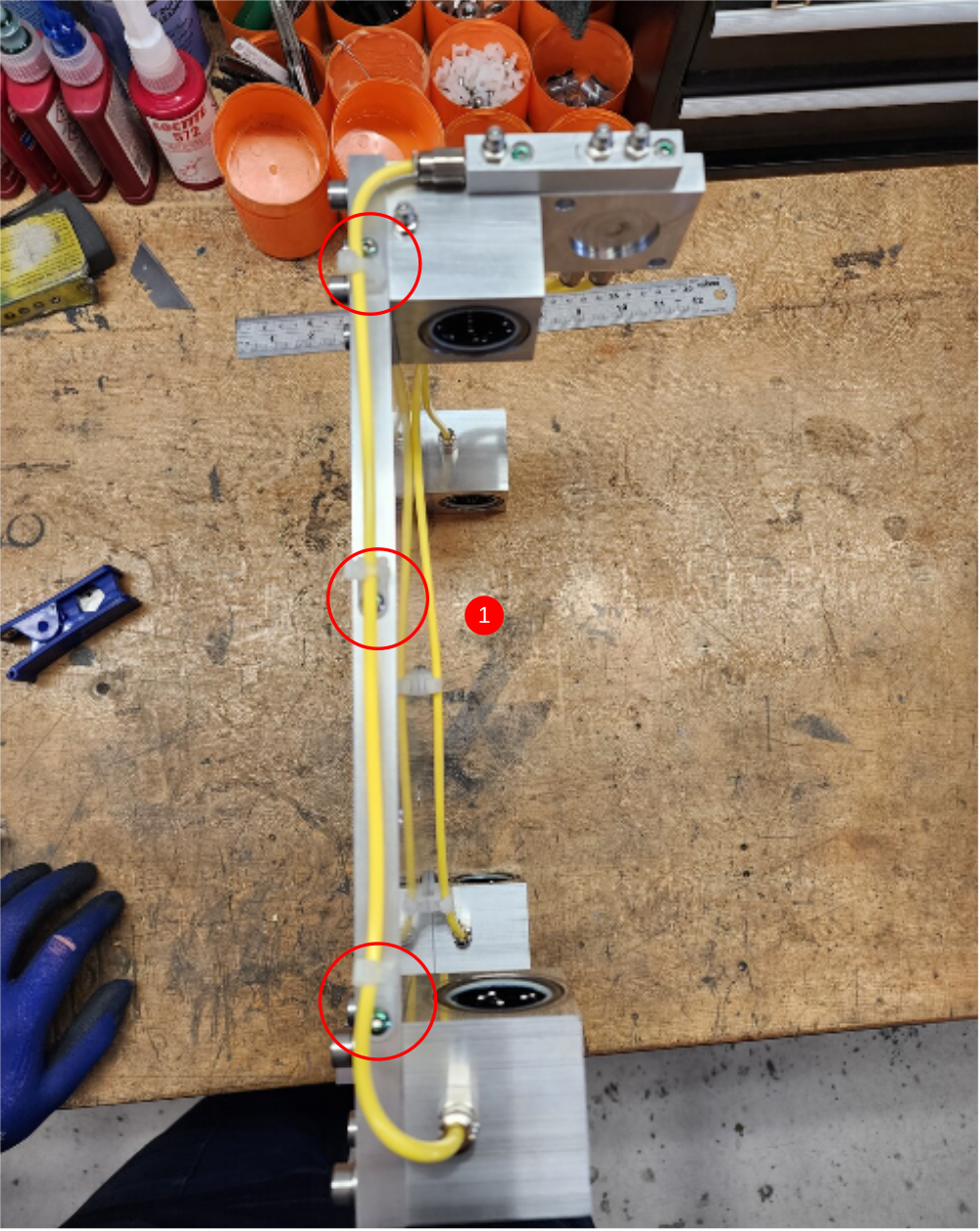
Étape 9 - Assemble rear grease line
1 Fit 3 off m4 tie bases and secure with M4 x 6 button heads at indicated points
2 fit and secure 2 lengths of 4mm yellow grease line and secure as shown

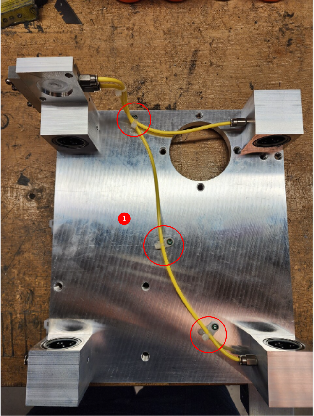


Étape 10 - Add front grease line
1 Add 3 off m4 tie base and secure with M4 x 6 button screws as shown
2 Cut and fit 1 off yellow grease pipe to follow route indicated

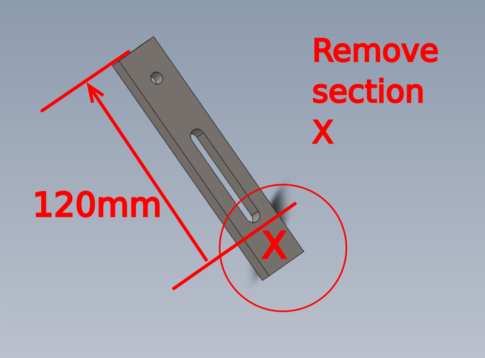
Étape 11 - Important Check
ECR has been raised to amend part D0004734 02/04/24
Amended to length has been requested. Part now needs to be 120mm long instead of 139.7mm
If supplied part has not been produced to shorted length, please rework part to new length of 120mm long ensuring a good quality of finish is achieved when cutting

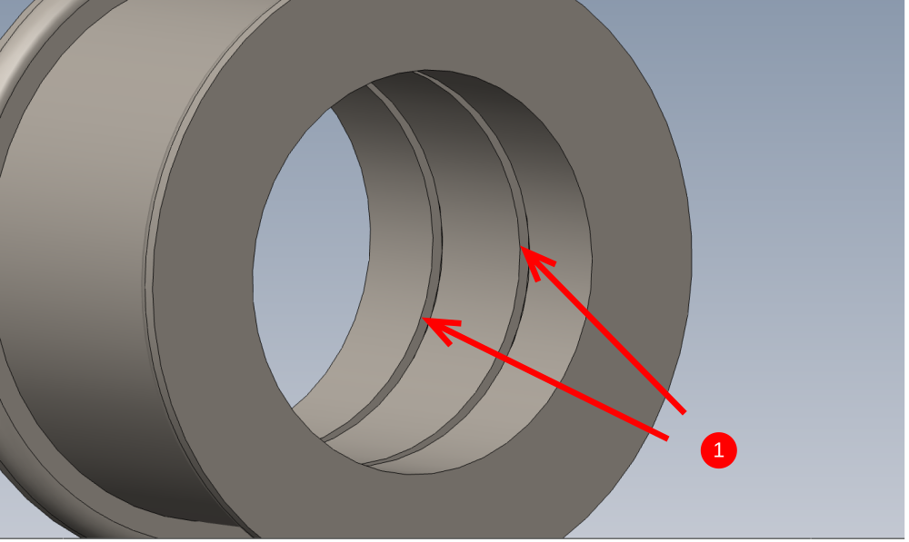
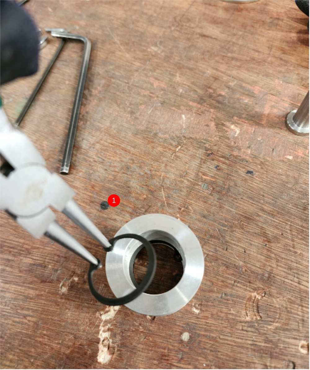
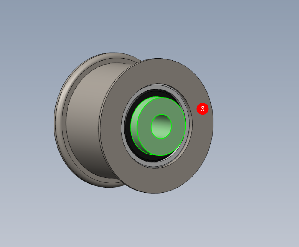
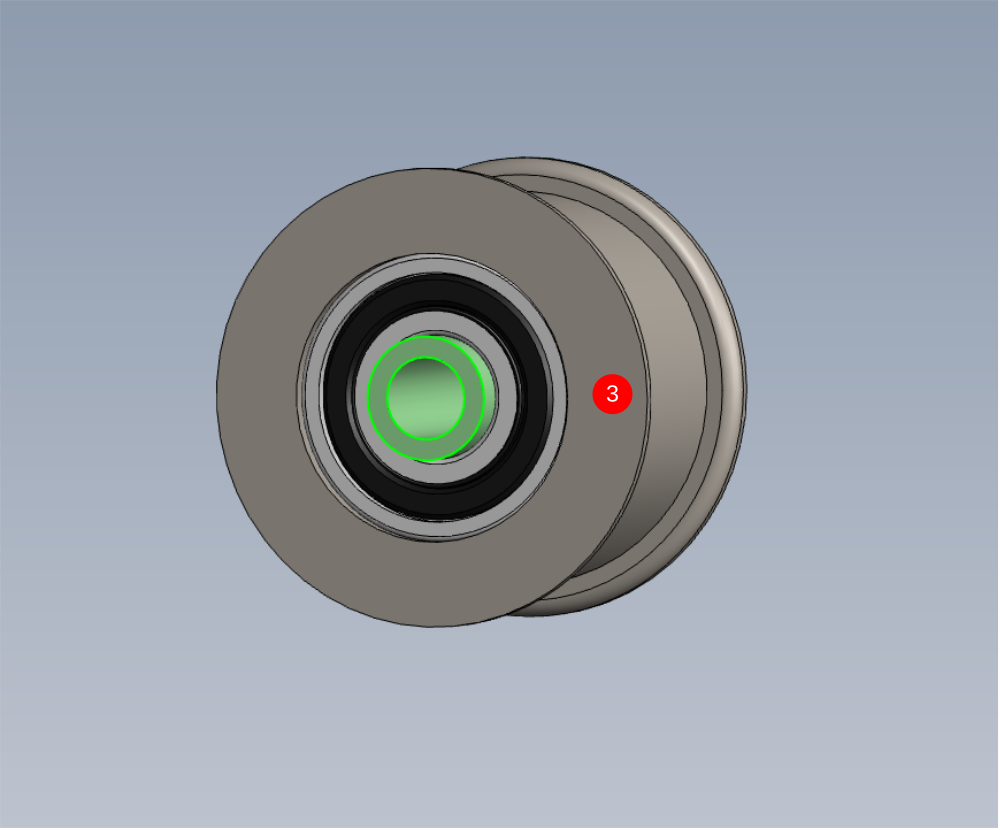
Étape 12 - Assemble tensioner pulley
1 Add two 28mm internal circlips to D0004733 Belt Adjuster Pulley
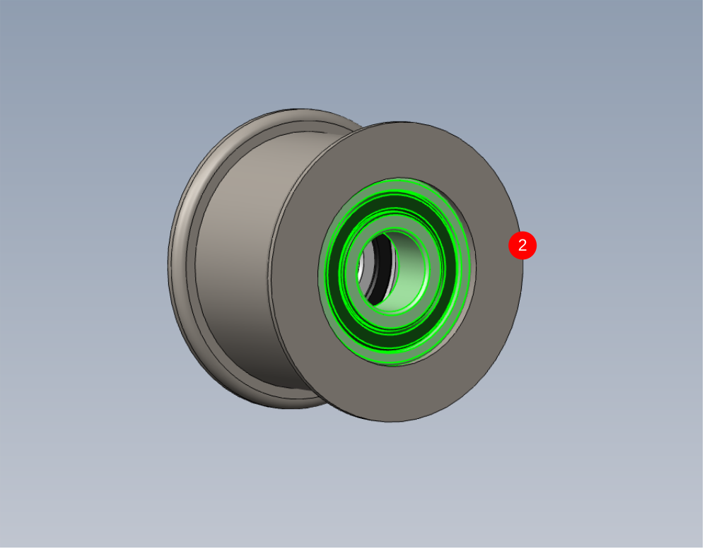
2 Fit 2 off B0000002 Bearing to pulley as indicated. Be observant of bearing fit, if bearing fit is loose use Degreaser and apply Loctite 641
If fit is tight ,check components to drawings
3 Fit D0004735 Belt Adjuster Pin as shown, observing above regarding correct fitment. Check smooth operation of bearings once fitted

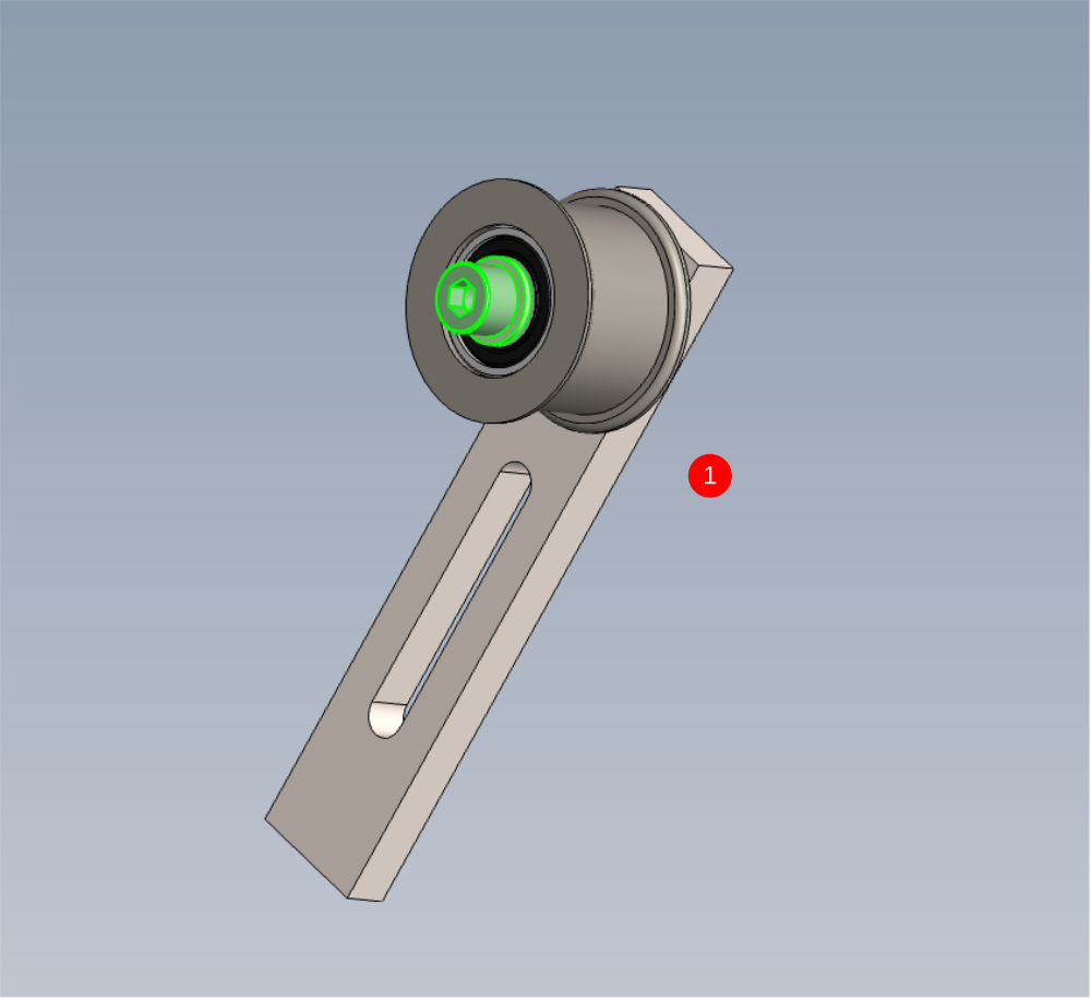
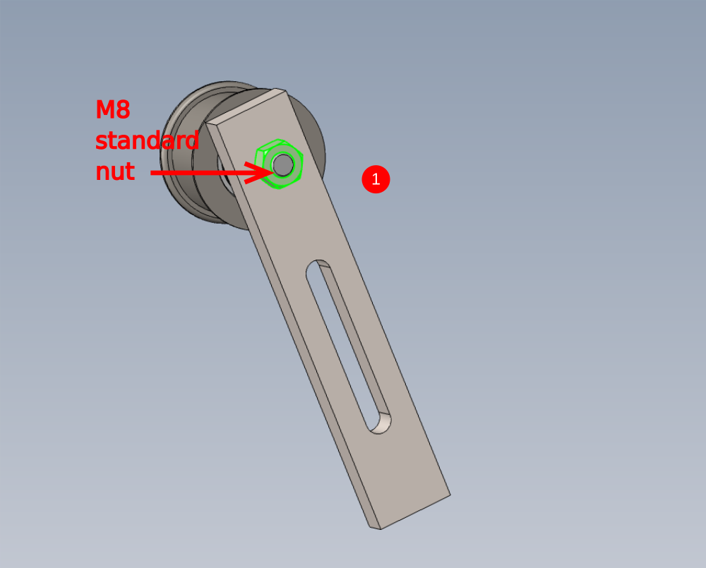
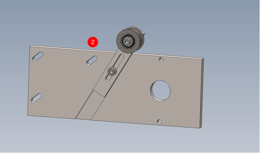
Étape 13 - Mount pulley to adjuster bar and motor plate
Please capture pictures for these steps
1 Fit pulley as shown to D0004734 Belt Adjusting Bar using M8 x 50 set bolt, M8 Penny washer and backed off with M8 standard nut.
2 Fit assembly to D0004078 Motor Plate as shown using M8 x 25 socket cap and Heavy duty M8 washer

Draft
 Français
 English
 Deutsch
 Español
 Italiano
 Português