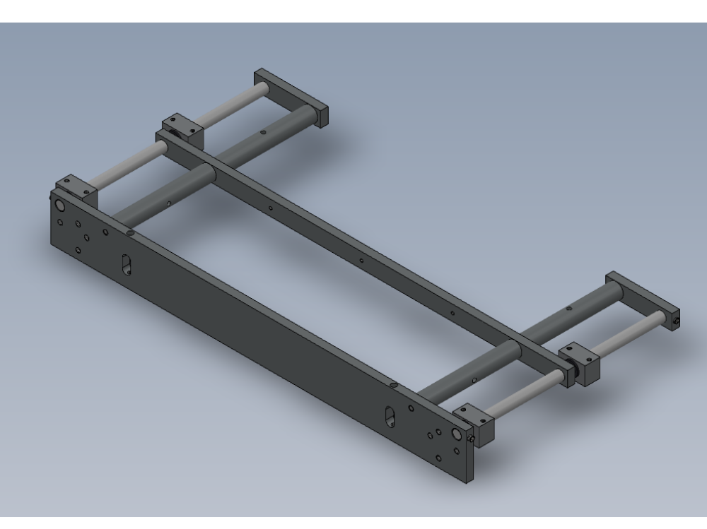
Bench assembly details for top table slide assembly

Difficulté
Moyen
Durée
1.5 heure(s)
Sommaire
- 1 Introduction
- 2 Étape 1 - Unless otherwise stated
- 3 Étape 2 - Orientation
- 4 Étape 3 - Prepare parts
- 5 Étape 4 - Fit bearings
- 6 Étape 5 - Prepare support bar
- 7 Étape 6 - Assemble Frame
- 8 Étape 7 - End plate alignment
- 9 Étape 8 - Add tie base
- 10 Étape 9 - Fit Grubscrews for adjustment
- 11 Commentaires
Introduction
Tools Required
Standard hex key set
Consumable M8 studding
Hacksaw and file
16mm hand reamer
1 meter straight edge
Parts Required
B0000034 Linear Bearing: Ø16 x 30 Compact (Metal Case Only) x 4
D0004138 Centralising Bearing Block x 4
D0004337 Slide Bar Holder x 1
D0004338 Slide Support Bar x 1
D0004545 Slide Support End x 2
D0005235 Support Post x 2
D0005236 Support Post x 2
H0004624 Shaft 16mm: 343 Centralise x 2
Étape 1 - Unless otherwise stated
All bolts to have Loctite 243 adhesive applied unless otherwise stated
All Threaded Pneumatic connections to have Loctite 570 applied
All bolts to be pen marked once adhesive applied and correct tension added

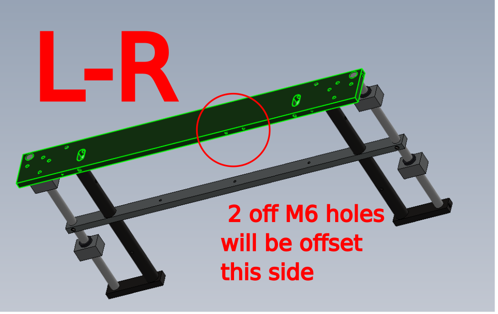
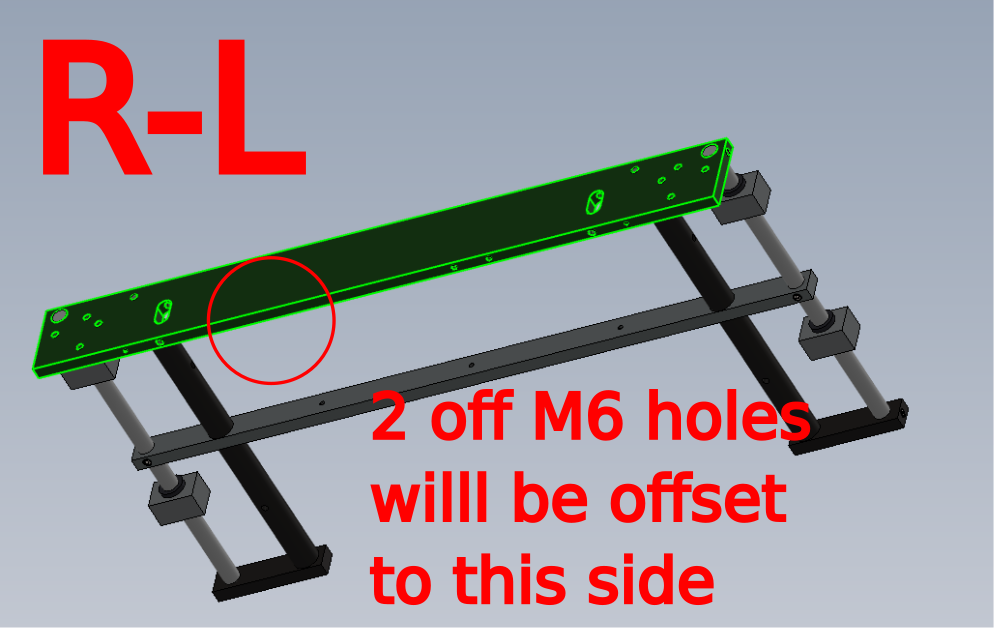
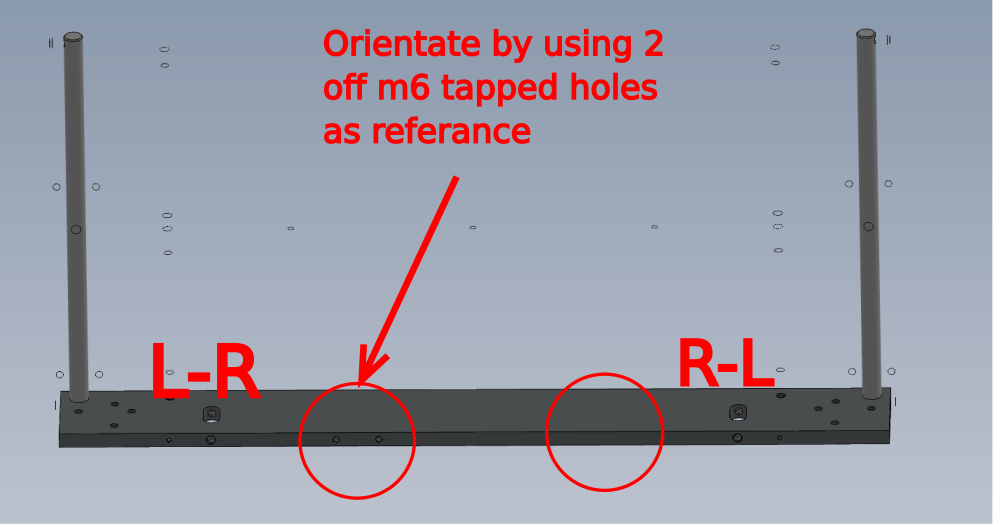
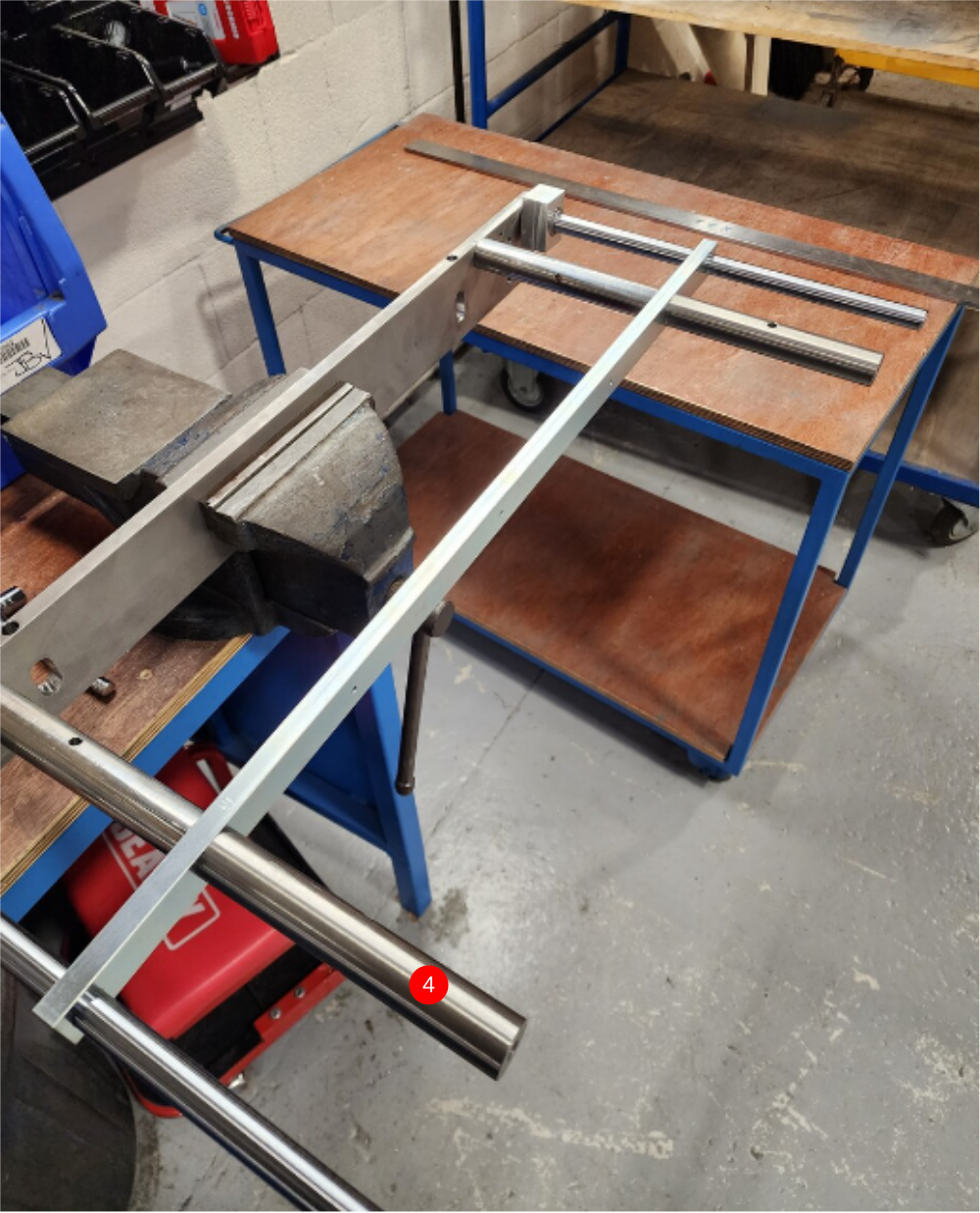
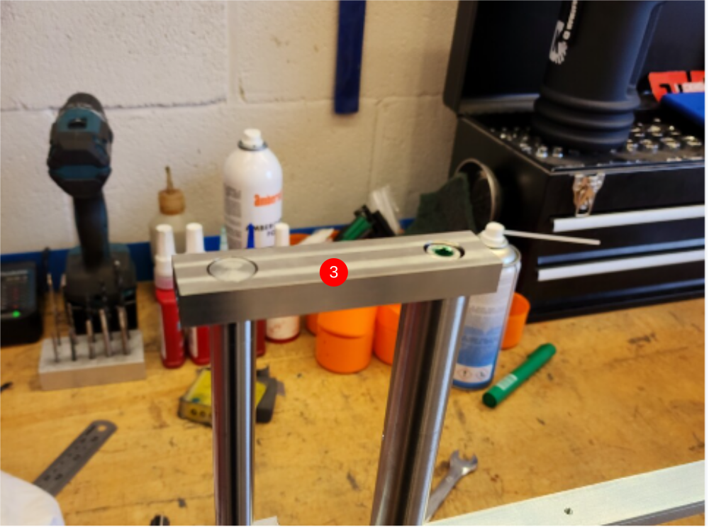
Étape 2 - Orientation
Please images for orientation of builds
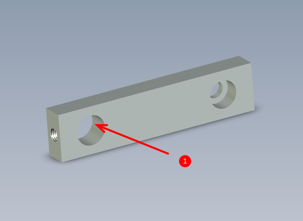
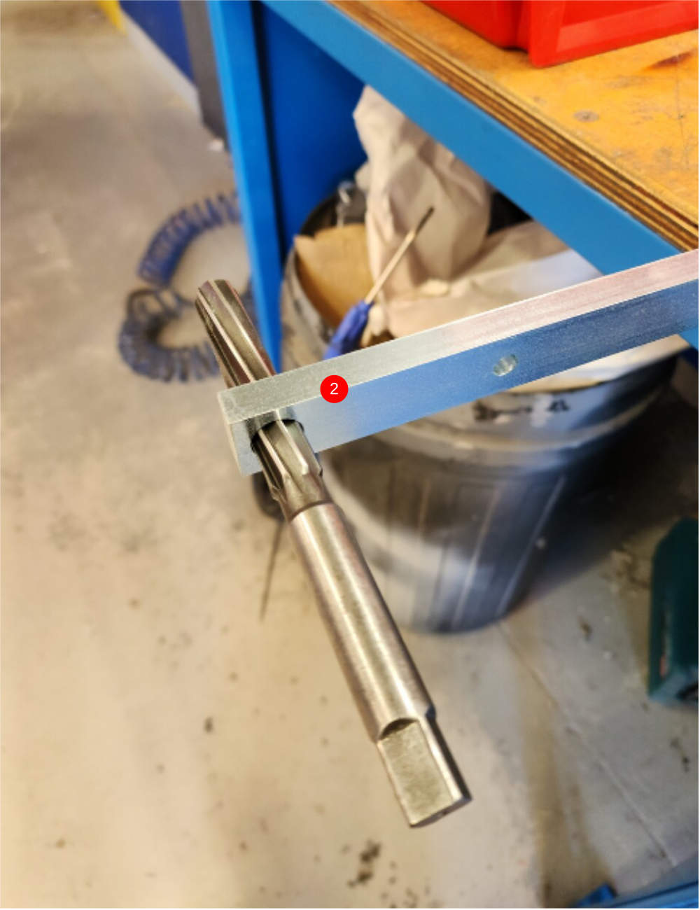
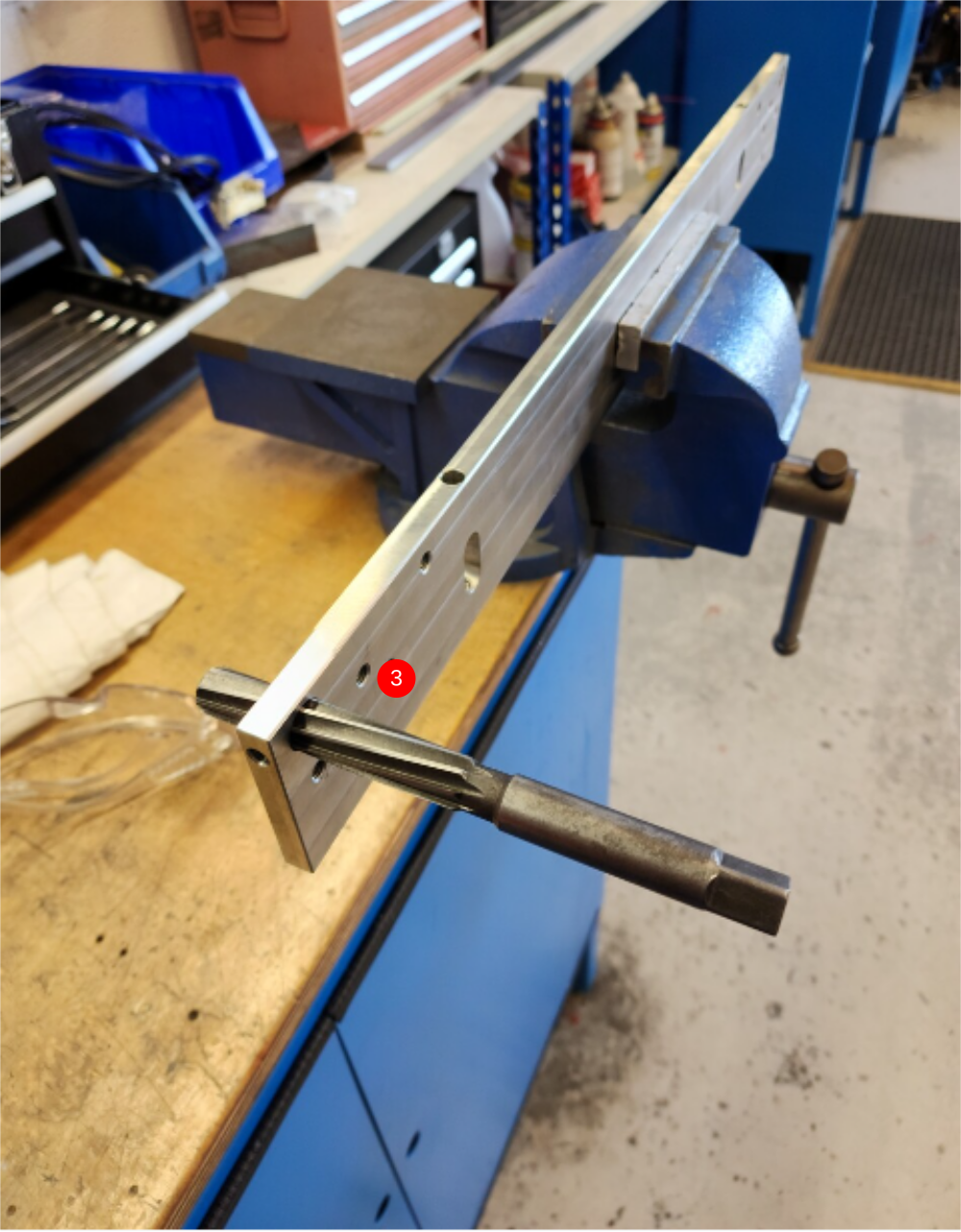
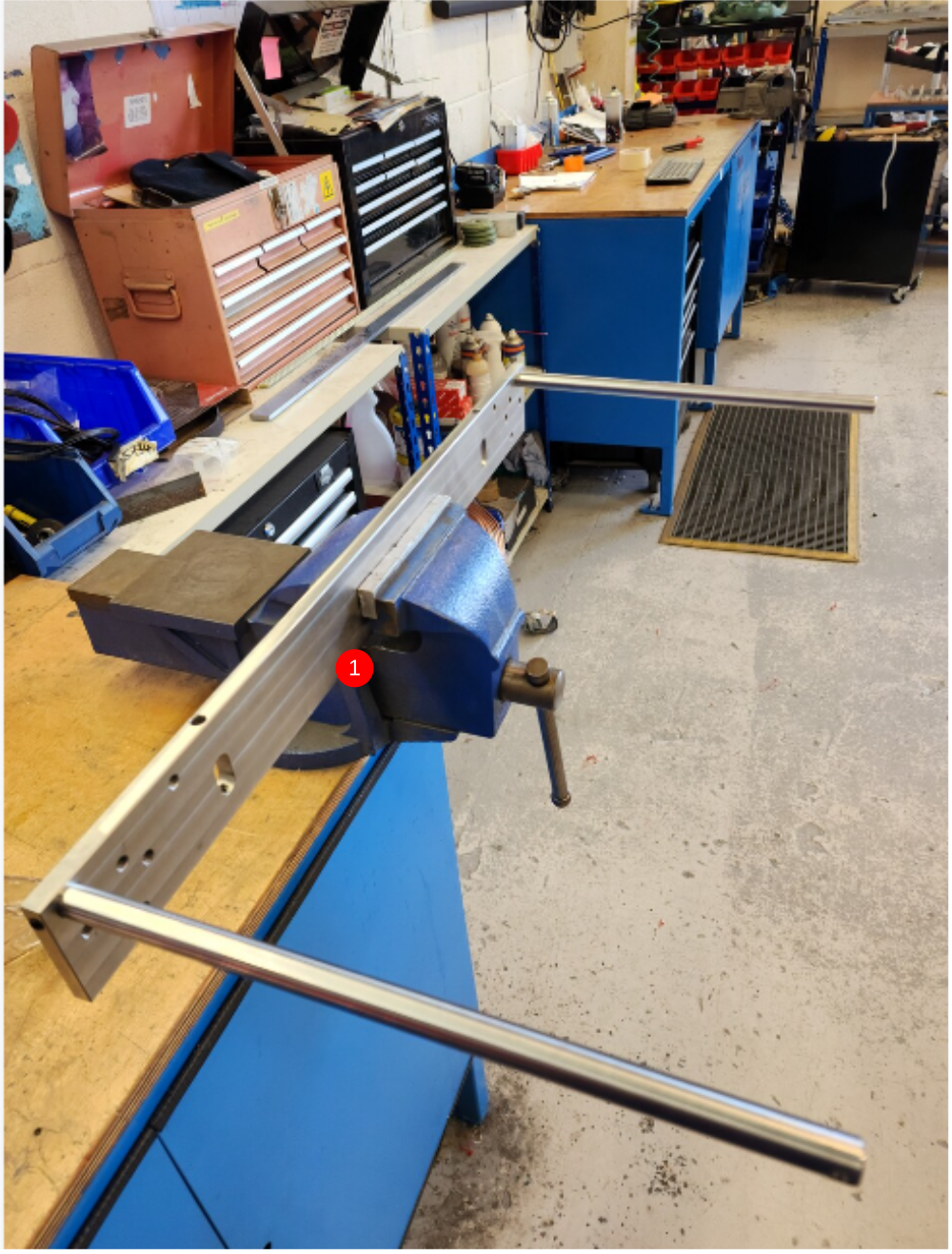
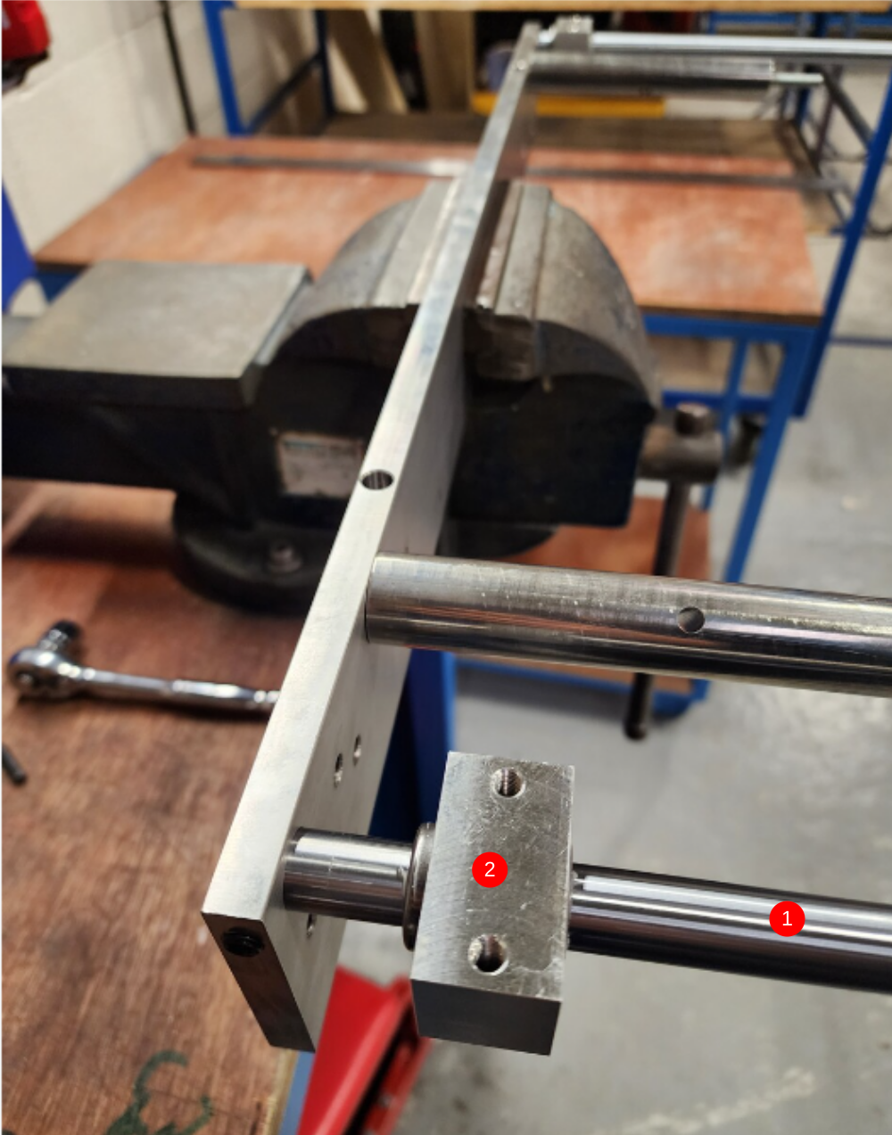
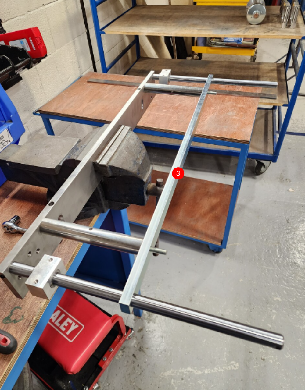
Étape 3 - Prepare parts
Use 16mm hand reamer to check sizing of bores in following parts
1 D0004545 Slide Support End x 2
2 D0004338 Slide Support Bar x 1
3 D0004337 Slide Bar Holder x 1
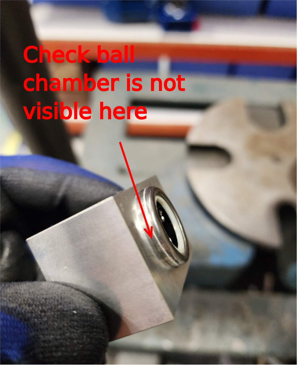
Étape 4 - Fit bearings
1 Degrease 4 off D0004138 Centralising Bearing Block
2 Use press to fit4 off B0000034 Linear Bearing. Fit bearing so yellow seal is almost flush with bearing block face
3 Apply grease to bearings


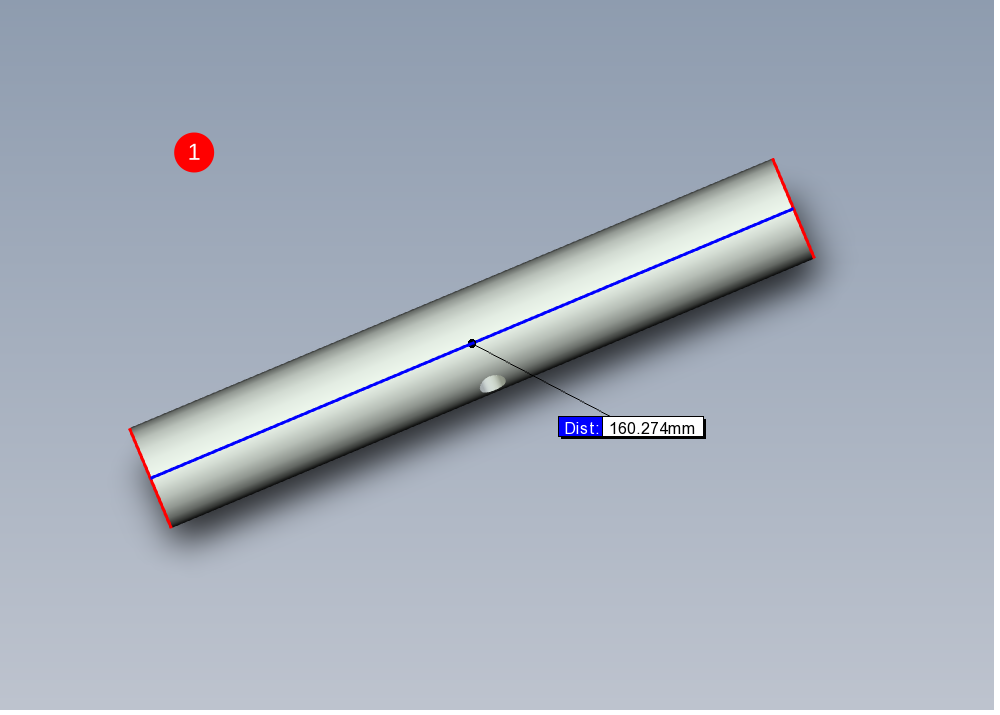
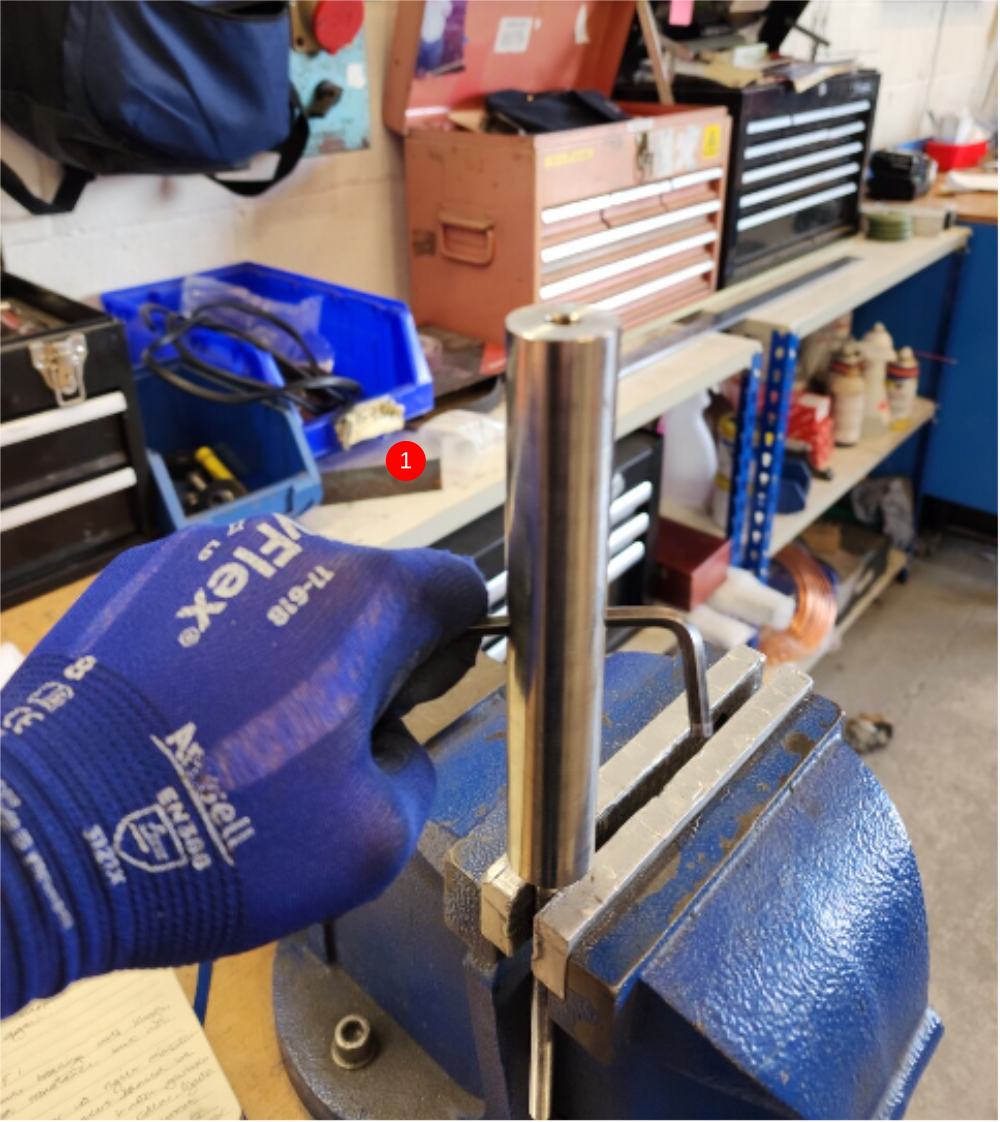
Étape 5 - Prepare support bar
1 Identify 2 off D0005236 Support Post. Check length measures 160mm
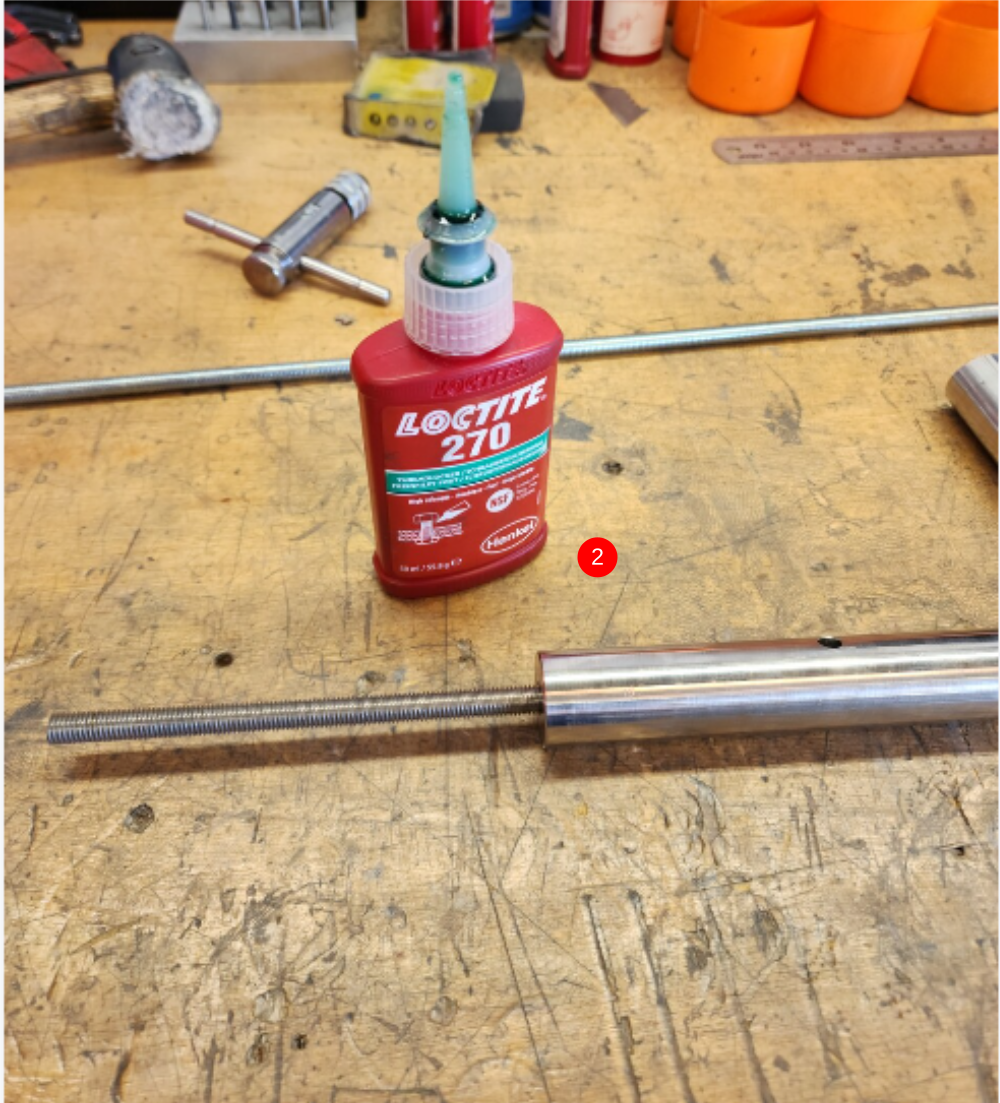
2 Use loctite 270 and fasten a length of M8 studding into one end and tighten
3 Cut M8 studding with hacksaw to leave 12.7mm protrusion as shown
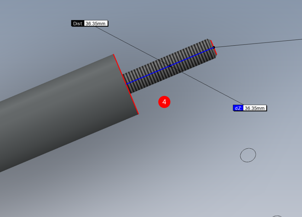
4 Fit studding to other end using steps above but cut to 36mm
5 Repeat for second support bar
6 quality check cut threads. Threads should be dressed clean with a file once cut . Use an M8 nut to check quality of thread before fitting to assembly


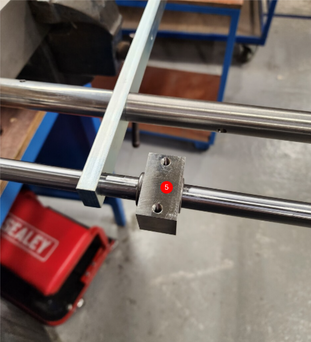
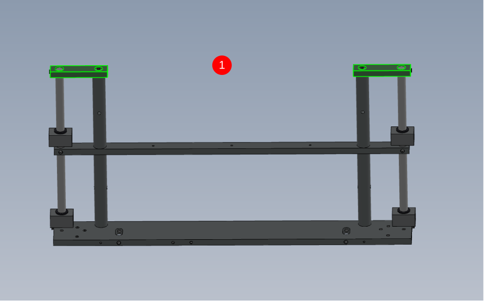
Étape 6 - Assemble Frame
1 Orientate D0004337 Slide Bar Holder as shown and fit 2 off H0004624 Shaft 16mm: 343 and secure with 2 off M x 12 kcp grubscrews , ensuring dimple on shaft is correctly aligned with grubscrew
2 Fit 2 off bearing blocks as indicated . Fit 2 off pre assembled support bars as shown, using Loctite 243
3 Fit D0004338 Slide Support Bar and orientated as shown. Ensure M8 grubscrew holes face downwards as shown . Use hide hammer to creep bar evenly into position
4 Fit 2 off D0005235 Support Post as shown and finalise
5 Fit 2 bearing blocks orientated same as previous two fitted
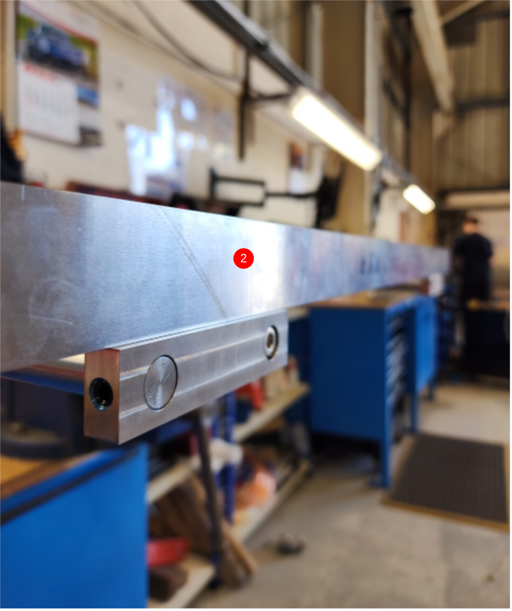
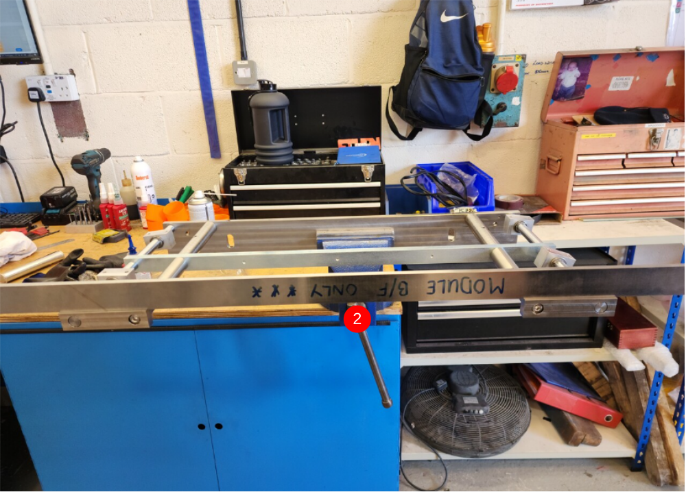
Étape 7 - End plate alignment
1 Fit 2 off D0004545 Slide Support End and fix with M8 x 20 socket cap and M8 x 12 kcp grubscrew per side . Do not finalise fasteners
2 Align end plates as shown using straight edge , to set end plates flat to each other
3 Finalise fixings and recheck end plate position has been held with straight edge
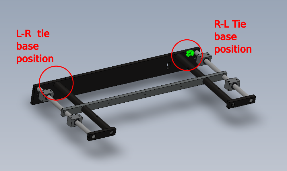
Étape 8 - Add tie base
Fit Large black tie base and secure with M5 x 10 button socket
Orientate as shown

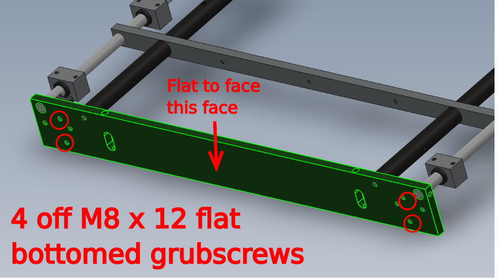
Étape 9 - Fit Grubscrews for adjustment
Fit 4 off M8 x 12 flat bottomed grubscrews as shown
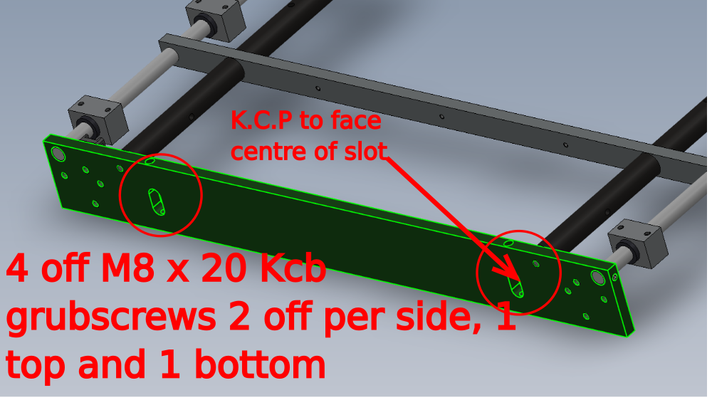
Fit 4 off Mx 20 kcp grubscrews as shown
Draft
 Français
 English
 Deutsch
 Español
 Italiano
 Português