Correct alignment protocol for subframe alignment

Difficulté
Très difficile
Durée
0 heure(s)
Sommaire
- 1 Introduction
- 2 Étape 1 - Unless otherwise stated
- 3 Étape 2 - Dowel in position
- 4 Étape 3 - Fit tie bars
- 5 Étape 4 - Add Z support jigs
- 6 Étape 5 - Y axis shafts
- 7 Étape 6 - Fit bearing blocks
- 8 Étape 7 - Finalise Y axis shafts
- 9 Étape 8 - Finalise M8 socket caps
- 10 Étape 9 - Fit Hard stops
- 11 Commentaires
Introduction
Tools Required
300mm engineers level
2 meter straight edge
1 meter straight edge
Standard hex key set
Standard spanner set
Z support jigs
Parts Required
D0000095 Bottom Plate x 2
D0006484 Front Tiebeam x 1
D0006485 Rear Tiebeam x 1
D0007681 Shaft Adjust Plate x 2
D0007683 Lower Beam Mount x 1
D0007684 Lower Beam Mount - Mirror x 1
D0007695 Platform (D8714) x 1
D0007787 Upper Beam Mount x 1
D0007835 Hard Stop x 2
D0008087 Z Servo Housing x 2
H0006025 Shaft 40mm: 939mm Flowline Y-axis x 2
H0007711 Shaft 40mm: 1350mm Microline Z (c/w M16 x 45 bolts) x 2
R0015296 Bench Assemble bearings AssembliesÉtape 1 - Unless otherwise stated
Use loctite 243 on all fasteners
Use Loctite 572 on all threaded pneumatic connections
Pen mark all bolts to show finalised

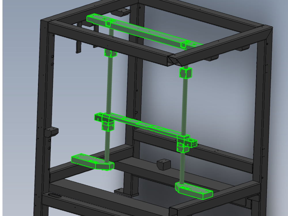
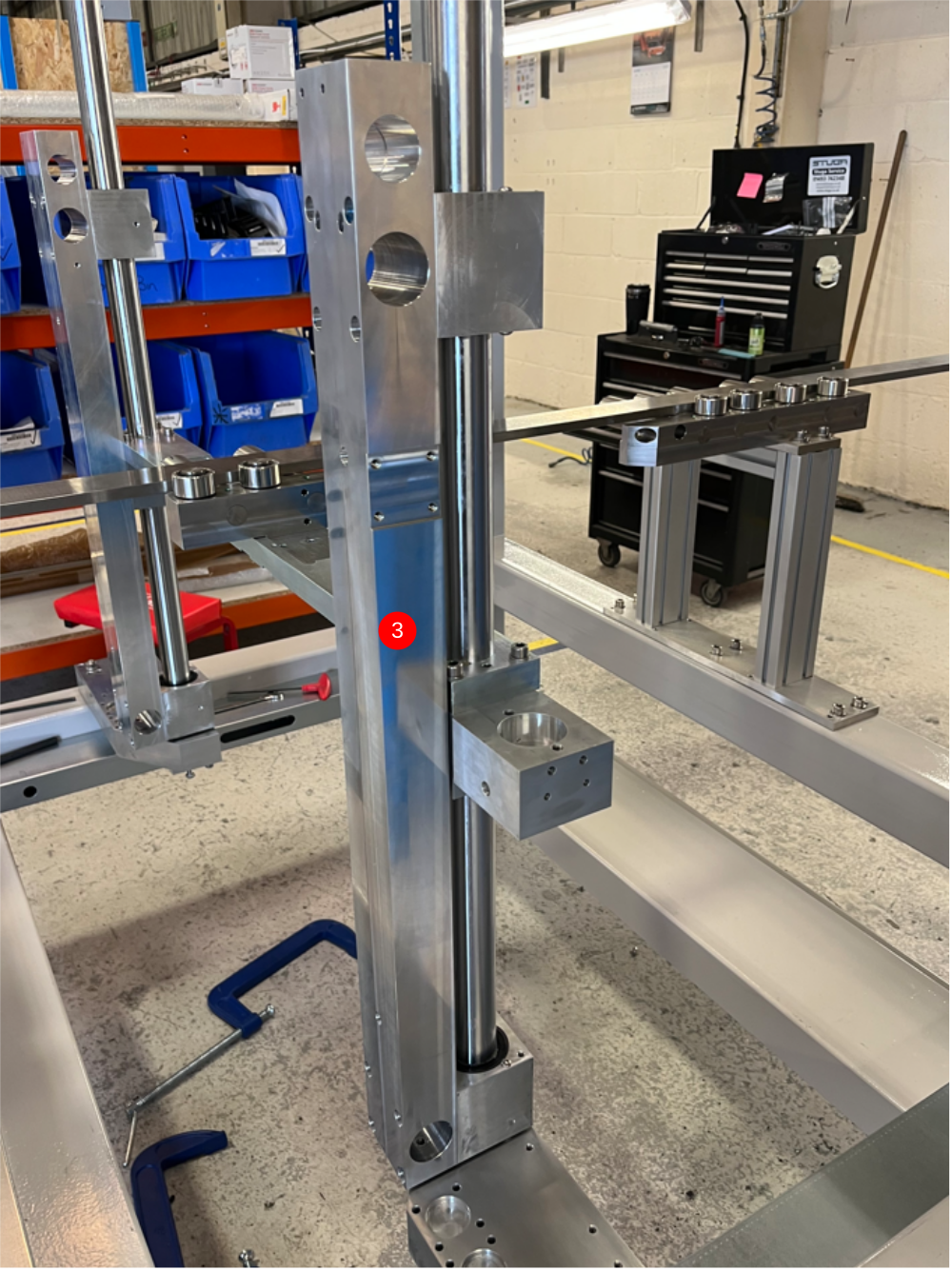
Étape 2 - Dowel in position
Subframe now requires dowelling in position
1 Drill upper beam mount with 10mm HSS 2 off , hole depth should be 20mm minimum into steel mounting tab . Use 10mm x 60mm spiral pin to fix
2 Dowel lower beam mounts . 4 off Drill indicated holes to 9.5 mm , then use 10mm hand reamer to finish . Fix with 10mm x 50 mm hardened dowel


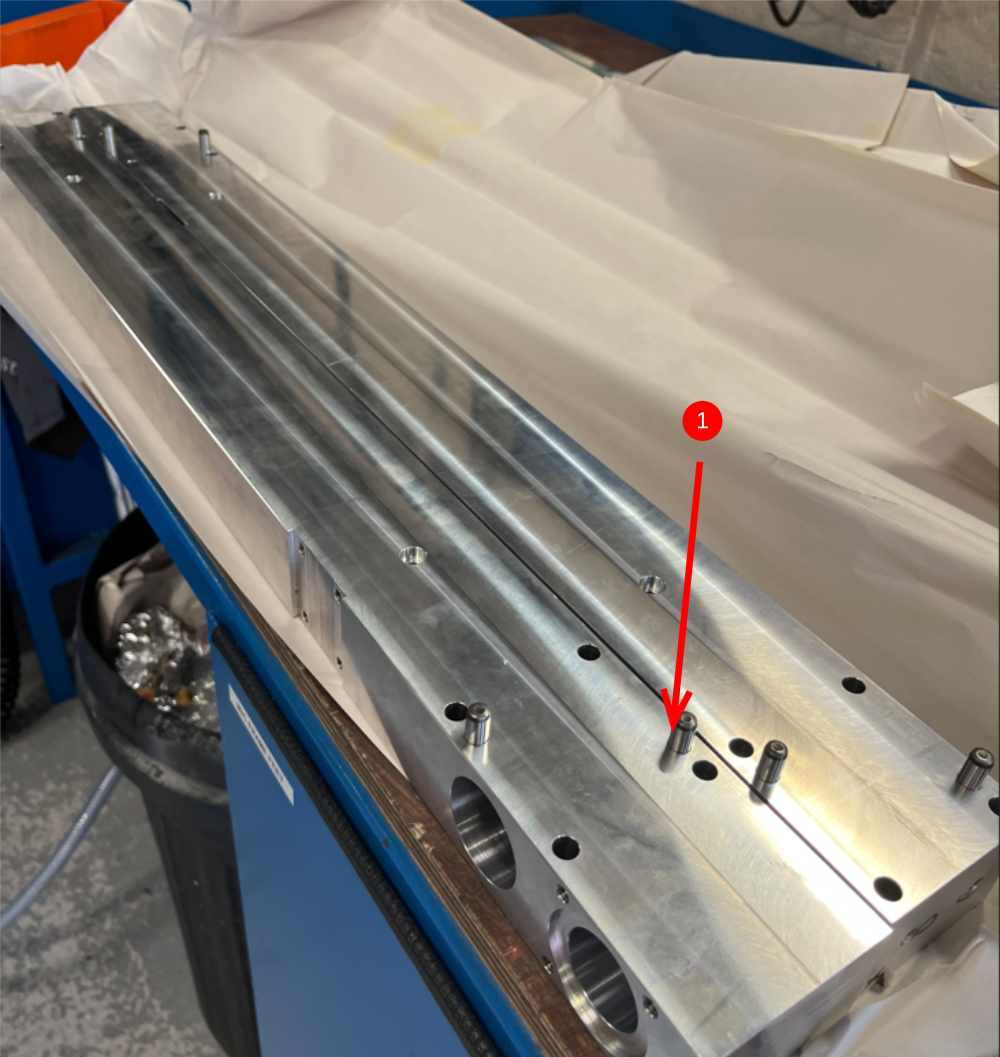
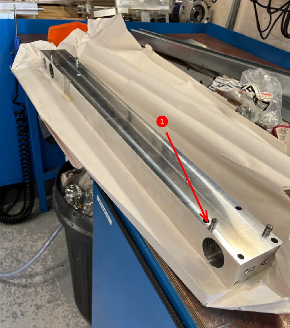
Étape 3 - Fit tie bars
use
D0006484 Front Tiebeam x 1
D0006485 Rear Tiebeam x 1
1 Fit 4 off 8mm x 24 mm hardened dowels to each tie bar as shown
2 Align D0006485 Rear Tie beam with bearing blocks and use 8 off M8 x 50 socket caps to fix. Use fasteners to evenly pull faces together , alternate between top and bottom fasteners to pull faces together parallel
3 Align D0006484 Rear Tie beam with bearing blocks and use 8 off M8 x 50 socket caps to fix. Use fasteners to evenly pull faces together , alternate between top and bottom fasteners to pull faces together parallel
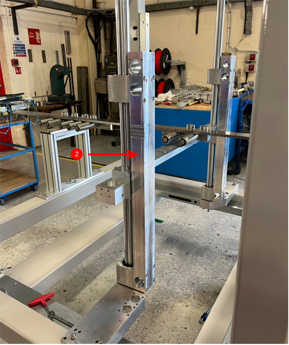
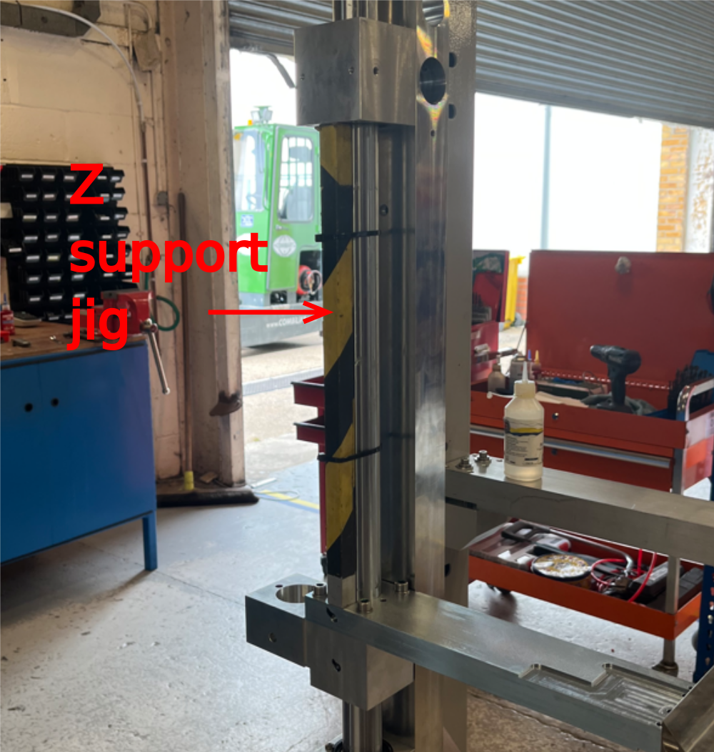
Étape 4 - Add Z support jigs
Lift fitted tie bars up and insert 1 off per bar support jig as shown .
Secure with 2 off large tie wrap per jig
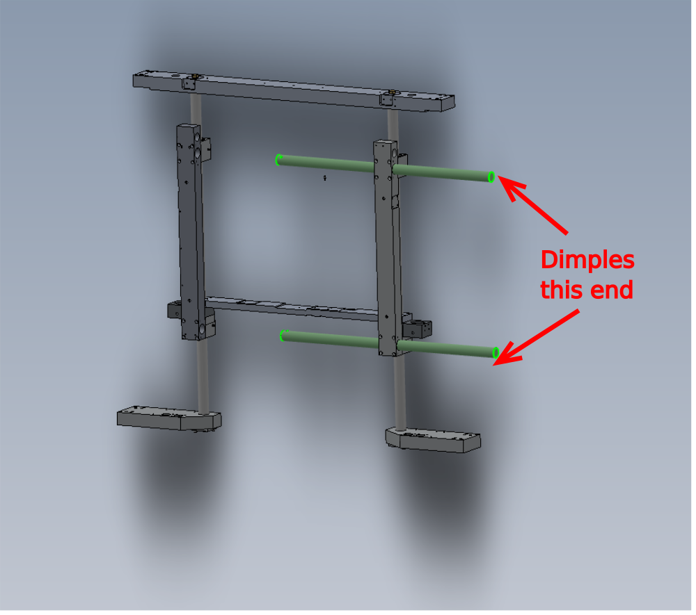
Étape 5 - Y axis shafts
Slide 2 off H0006025 Shaft 40mm: 939mm Flowline Y-axis into the position shown.
Ensure dimple position on shaft is marked clearly on end shaft as shon


Étape 6 - Fit bearing blocks
Fit 4 off bearing blocks from assembly R0015296 Bench Assemble bearings Assemblies
Orientate as shown .


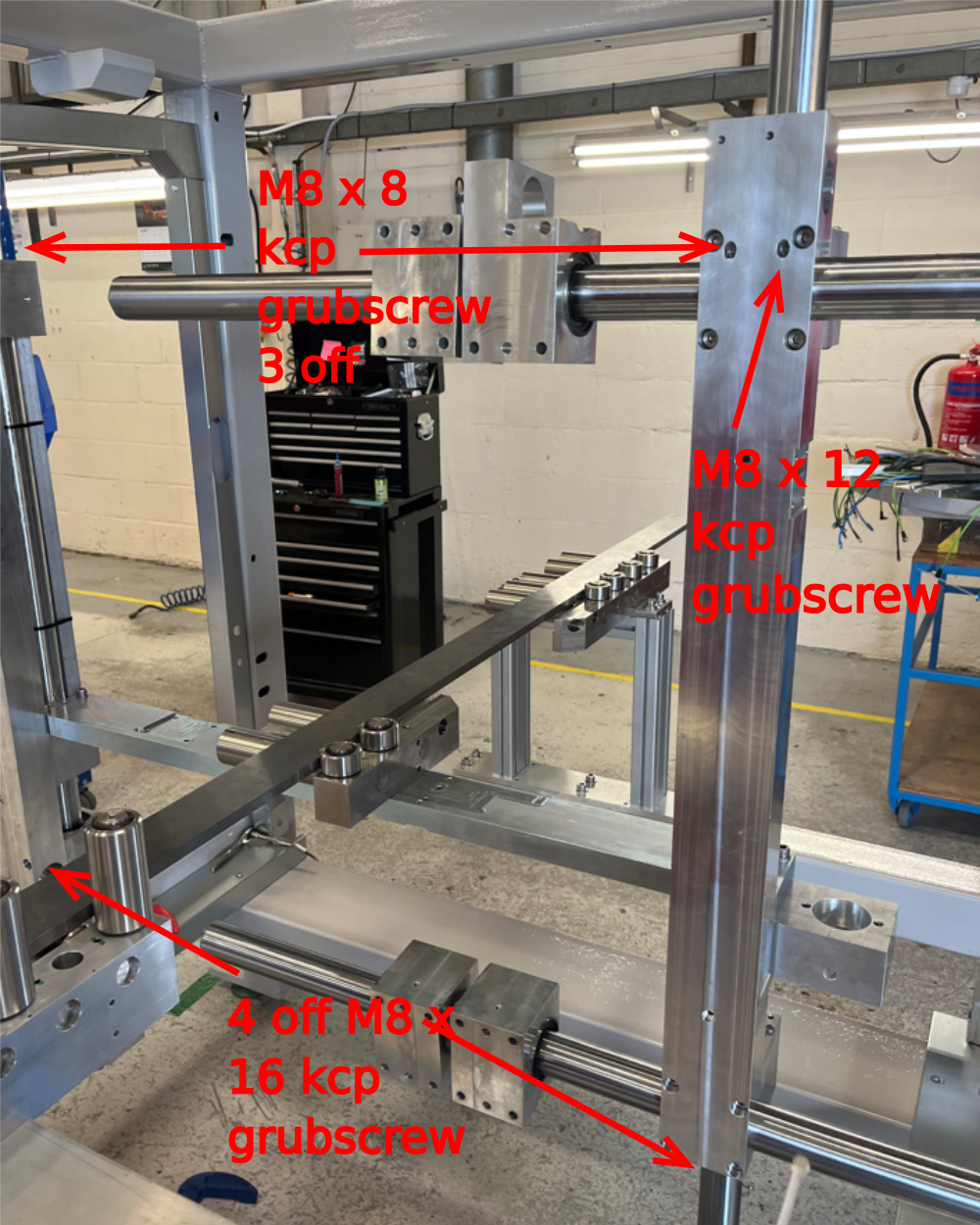
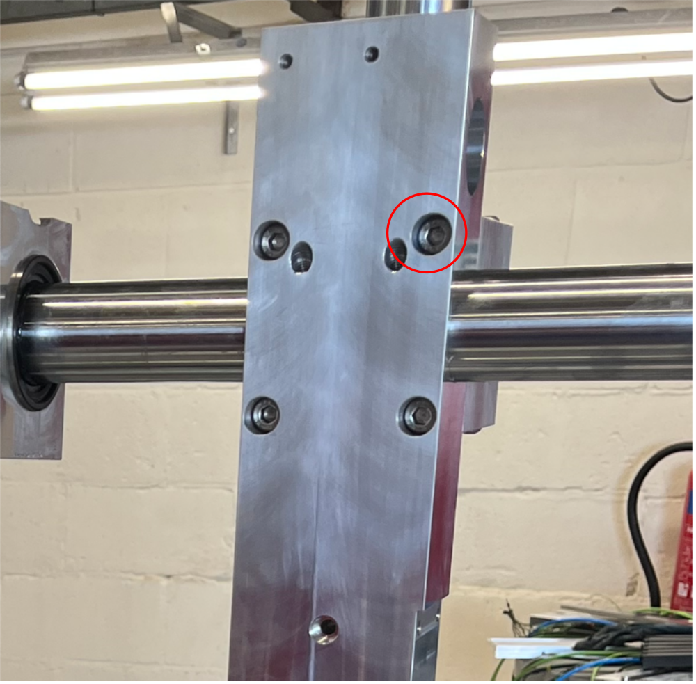
Étape 7 - Finalise Y axis shafts
Slide Y axis shafts into final position
1 Align dimples using shaft end mark .
Top shaft is at 45 degrees
Bottom shaft is at 180 degrees
See image for grubscrew sizes


Étape 8 - Finalise M8 socket caps
Individually remove each M8 socket cap (16 off) that secure the tie bars , apply adhesive and apply final tension
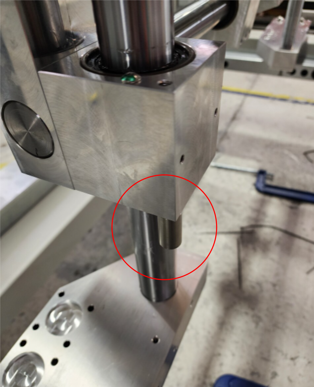
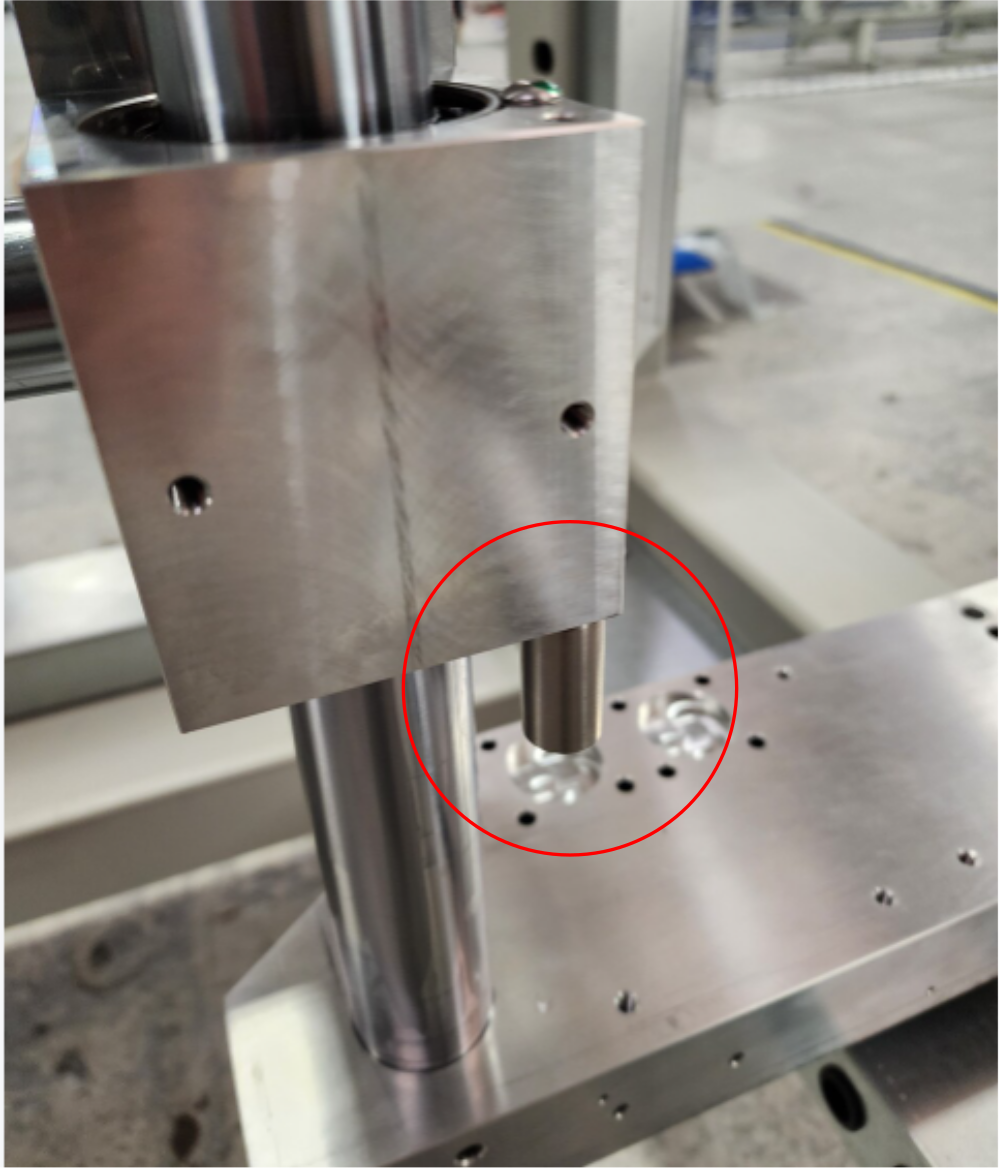
Étape 9 - Fit Hard stops
Fit 2 off hard stops to lower vertical shaft bearing blocks.
Use 2 off M6 x 30 socket caps to fix
Draft
 Français
 English
 Deutsch
 Español
 Italiano
 Português