| [version en cours de rédaction] | [version en cours de rédaction] |
| Ligne 21 : | Ligne 21 : | ||
Standard spanner set | Standard spanner set | ||
| + | |||
| + | Z support jigs | ||
Version du 28 juillet 2023 à 12:07
Correct alignment protocol for subframe alignment

Difficulté
Très difficile
Durée
5 heure(s)
Sommaire
- 1 Introduction
- 2 Étape 1 - Unless otherwise stated
- 3 Étape 2 - Level Frame
- 4 Étape 3 - Instal Upper beam mount
- 5 Étape 4 - Level upper beam mount
- 6 Étape 5 - Install Z axis shafts
- 7 Étape 6 - Assemble centre platform
- 8 Étape 7 - Fit Centre platform
- 9 Étape 8 - Fit lower beam mounts
- 10 Étape 9 - Level lower beam mounts
- 11 Étape 10 - Align lower beam mounts
- 12 Étape 11 - Check shaft pitching
- 13 Étape 12 - Attach bottom plate
- 14 Étape 13 - Quality check
- 15 Étape 14 - Quality check
- 16 Étape 15 - continue to part 2 of dokit
- 17 Commentaires
Introduction
Tools Required
300mm engineers level
2 meter straight edge
1 meter straight edge
Standard hex key set
Standard spanner set
Z support jigs
Parts Required
D0000095 Bottom Plate x 2
D0006484 Front Tiebeam x 1
D0006485 Rear Tiebeam x 1
D0007681 Shaft Adjust Plate x 2
D0007683 Lower Beam Mount x 1
D0007684 Lower Beam Mount - Mirror x 1
D0007695 Platform (D8714) x 1
D0007787 Upper Beam Mount x 1
D0007835 Hard Stop x 2
D0008087 Z Servo Housing x 2
H0006025 Shaft 40mm: 939mm Flowline Y-axis x 2
H0007711 Shaft 40mm: 1350mm Microline Z (c/w M16 x 45 bolts) x 2
R0015296 Bench Assemble bearings Assemblies
Étape 1 - Unless otherwise stated
Use loctite 243 on all fasteners
Use Loctite 572 on all threaded pneumatic connections
Pen mark all bolts to show finalised

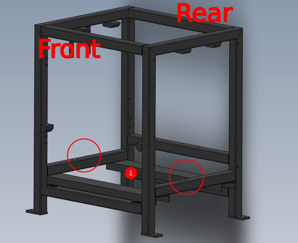
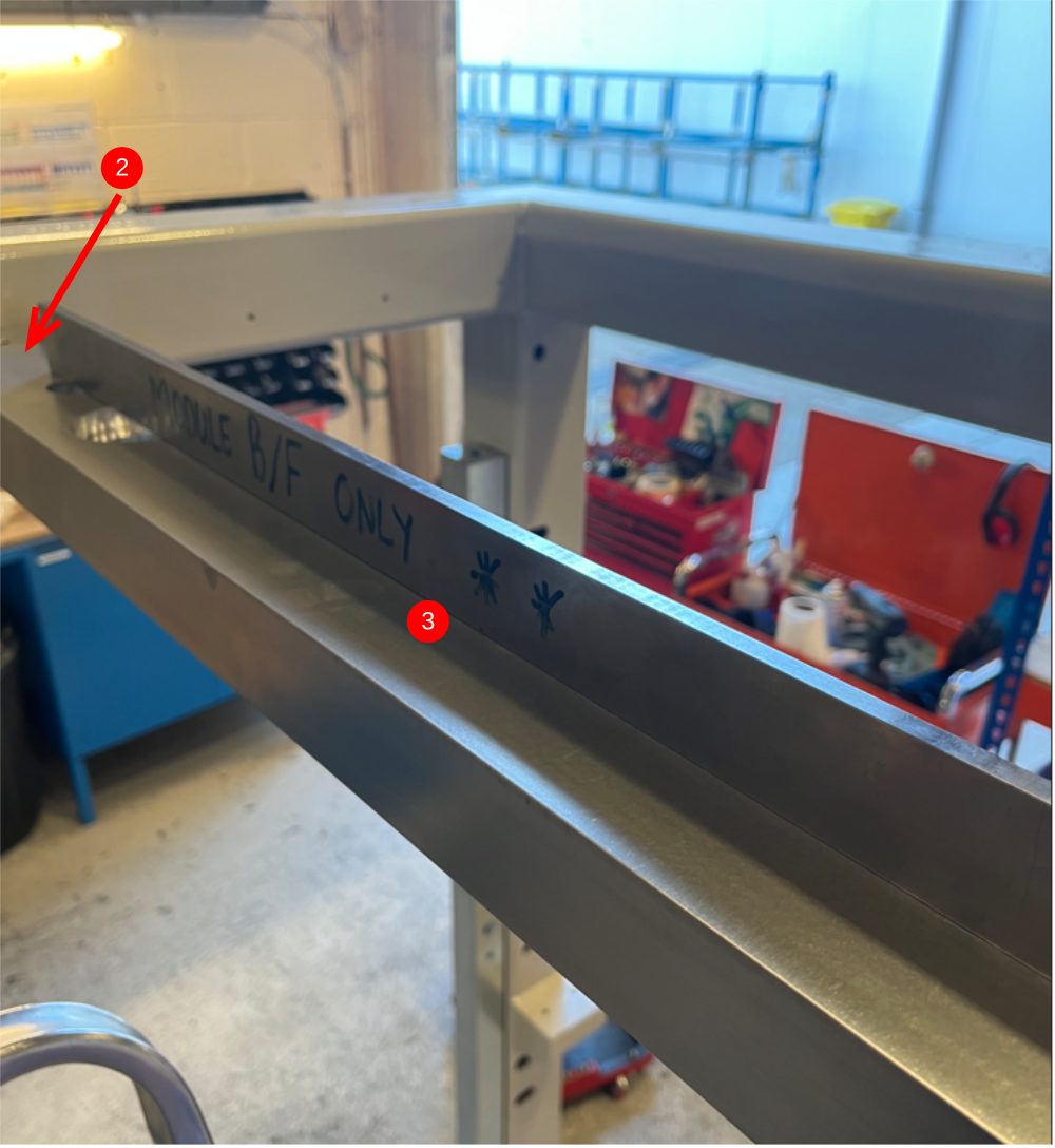
Étape 2 - Level Frame
1 Use engineers level to level frame at the indicated points . Any discrepancy between the two faces should be adjusted to be even both sides .
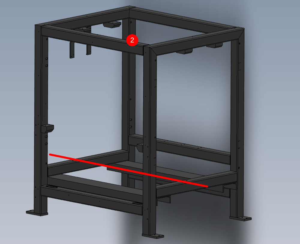
2 Use 2 meter straight edge and 300mm engineers level to level Y axis of machine at the indicated points

Étape 3 - Instal Upper beam mount
Mount and orientate D0007787 Upper Beam Mount x 1 as shown
Fix with M12 x 70 socket caps and A form washers , do not apply adhesive
Add 8 off M10 x 30 flat bottomed grubscrews

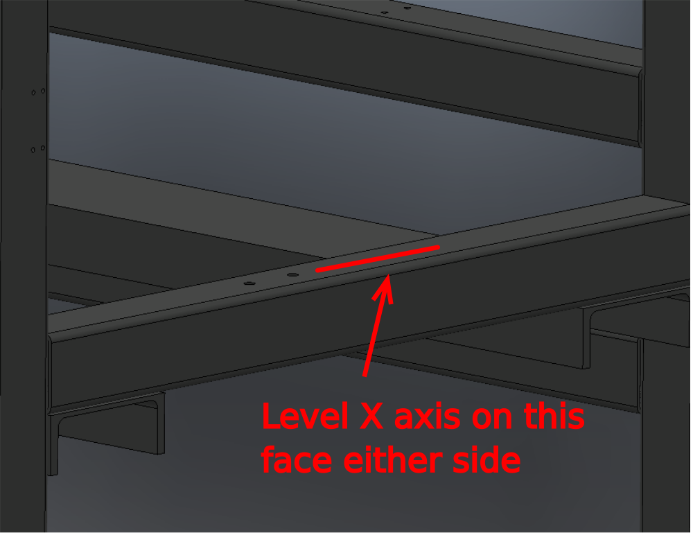
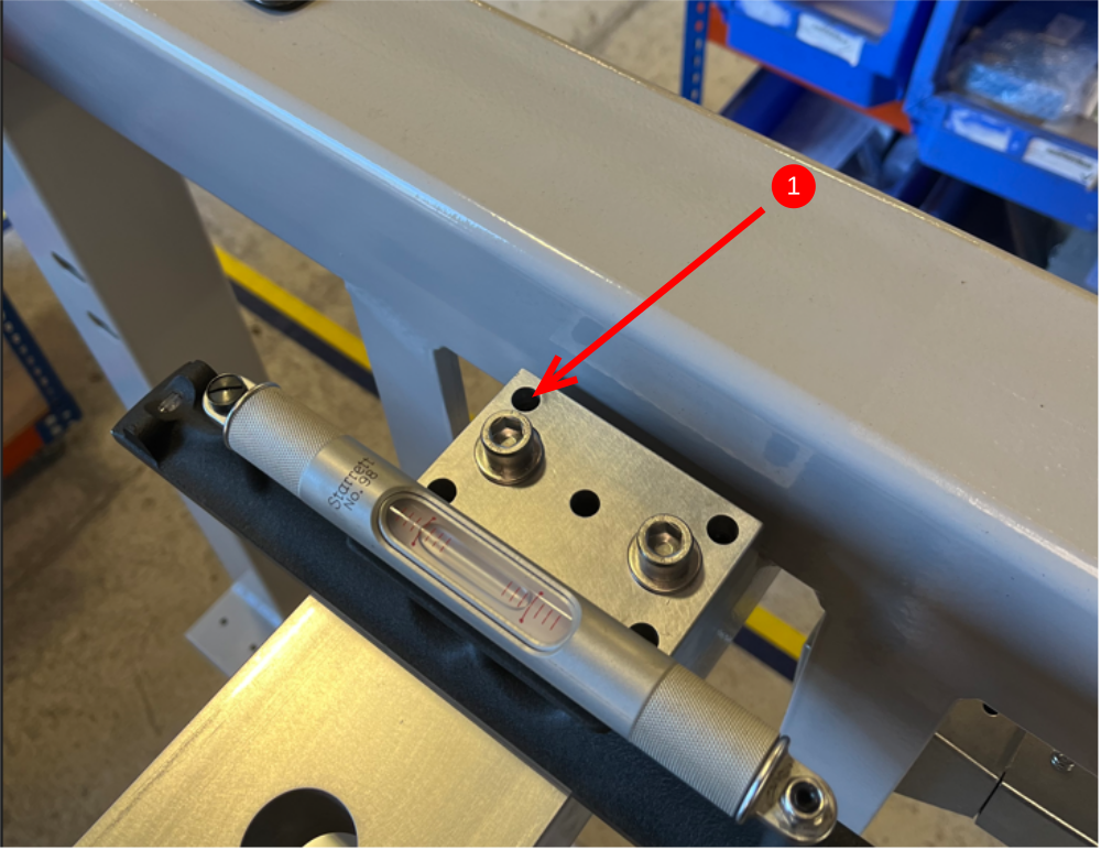
Étape 4 - Level upper beam mount
1 Level X axis on both sides of the beam at the indicated point using M10 grubscrews to adjust
2 Adjust Y Axis using grubscrews . only adjust one end up, as height needs to remain as close as possible to frame monting point.
Use 1 meter straight edge and engineers level
3 Check and adjust flatness by using 1 meter straight edge to gauge. Bias can be used on jacking grubscrews to manipulate the upper beam mount flat.
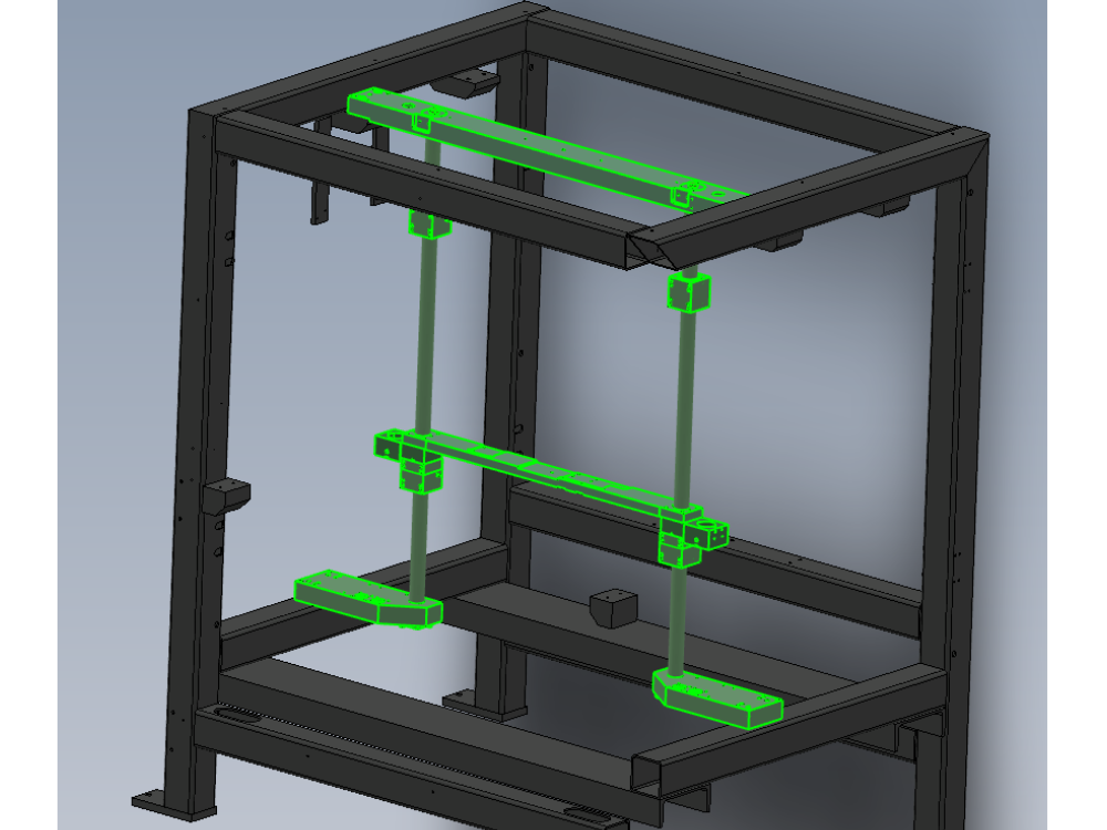
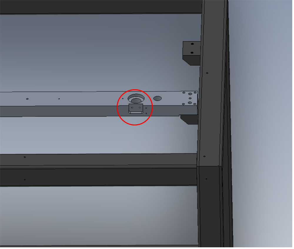
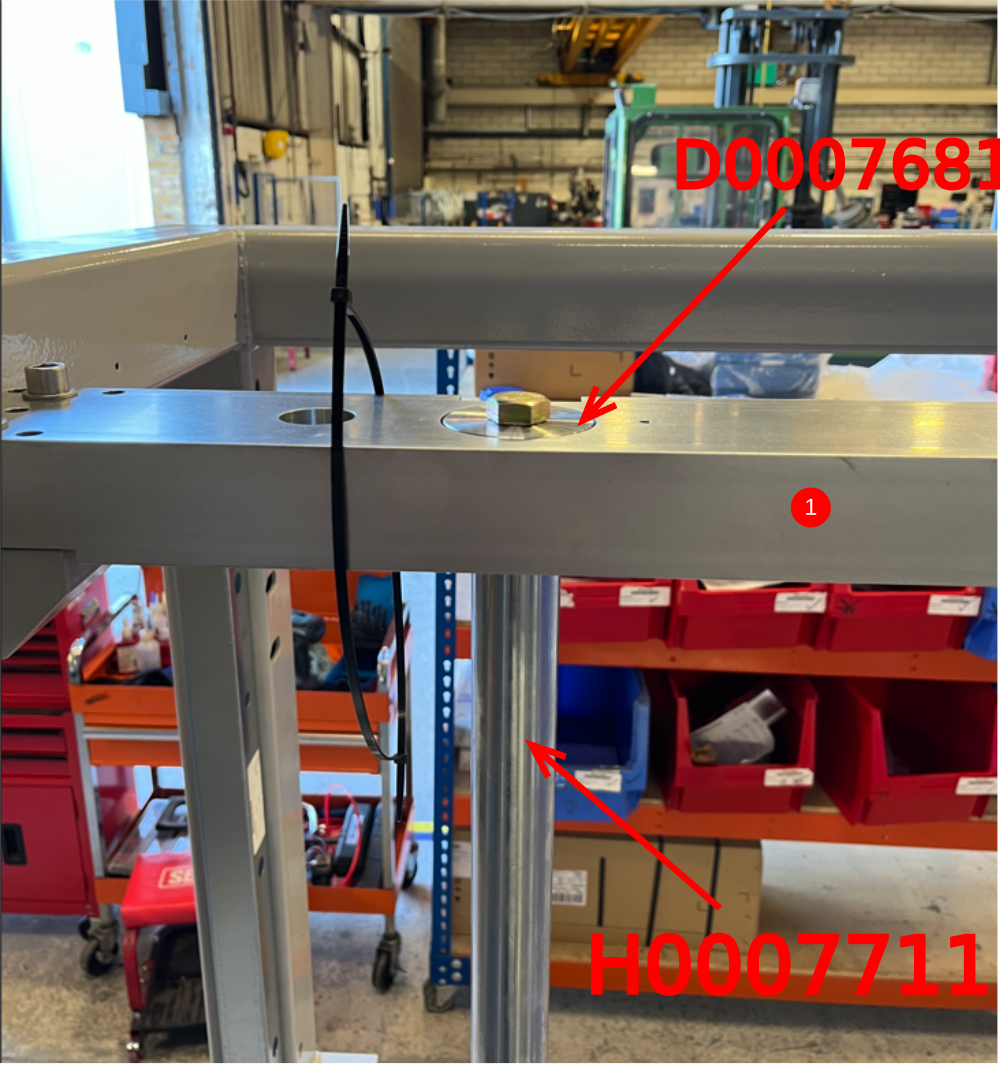
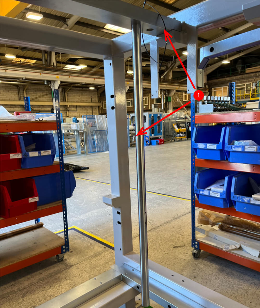
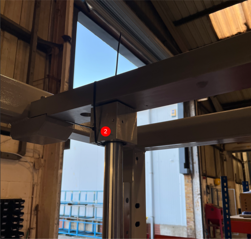
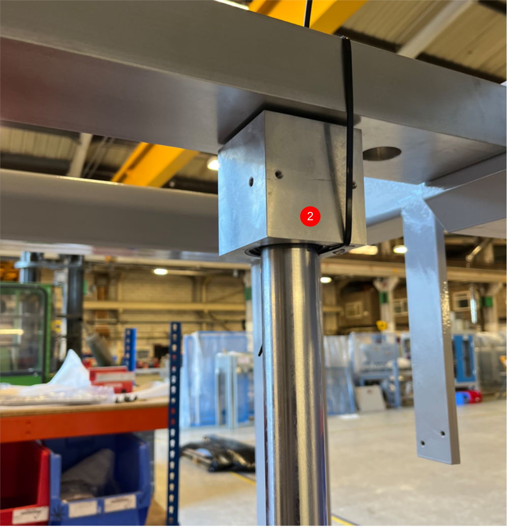
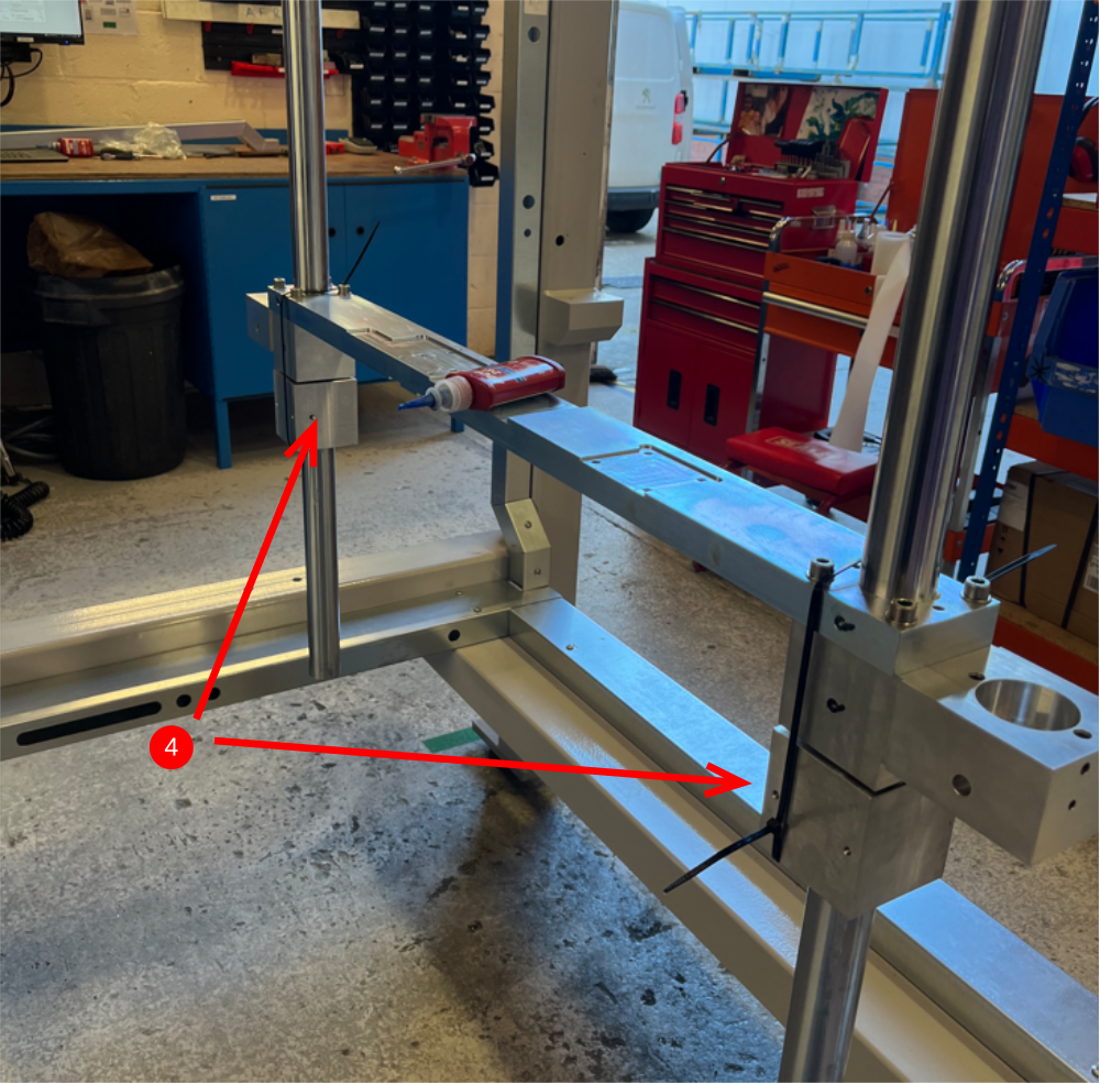
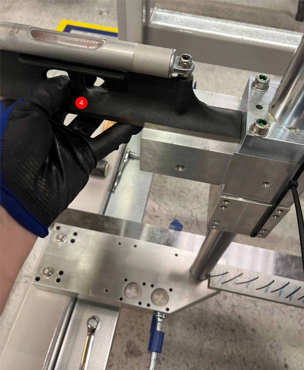
Étape 5 - Install Z axis shafts
1 Mount H0007711 Shaft 40mm: 1350mm Microline Z (c/w M16 x 45 bolts) x 2
and suspend in place with M16 x 45 hex head bolts and D0007681 Shaft Adjust Plate x 2
Add 2 off large black tie wraps per side as shown
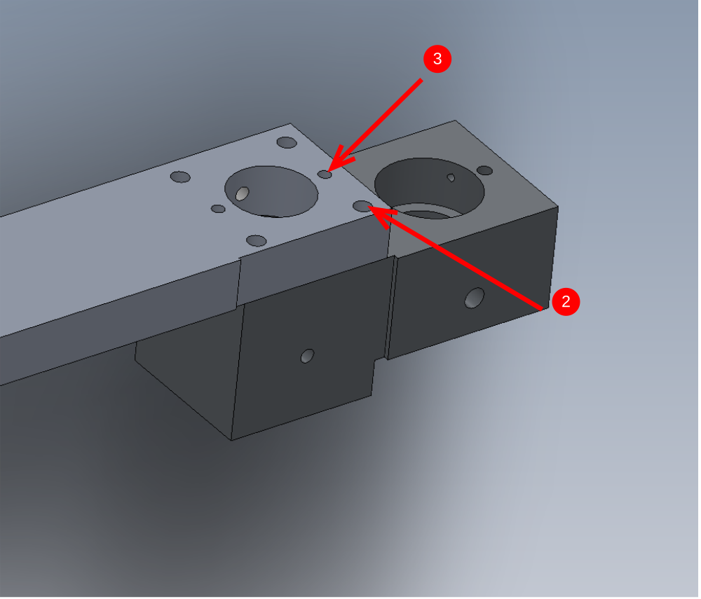
2 Fit 2 off bearing block from R0015296 Bench Assemble bearings Assemblies to z shafts orientated as shown.
M6 holes should face centre of machine and M8 holes and 8mm dowel holes should face front of machine
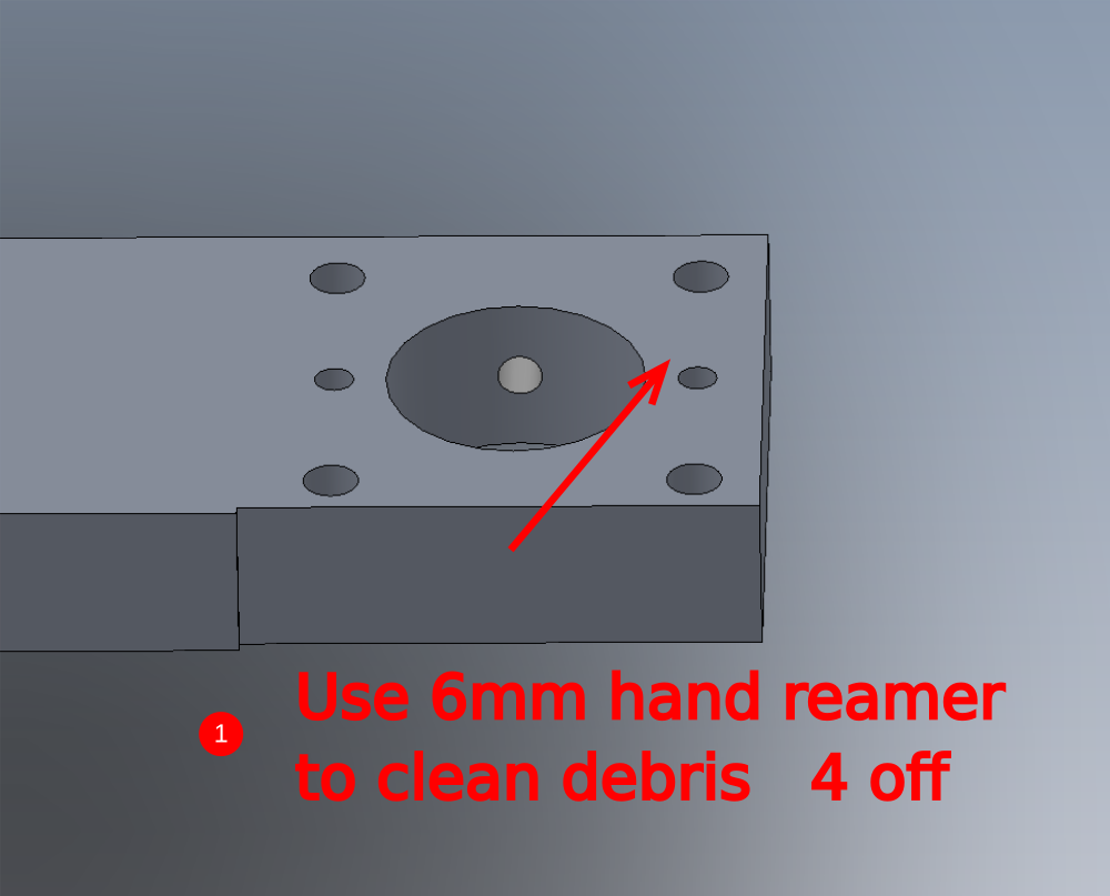
Étape 6 - Assemble centre platform
1 Prepare 6mm dowel holes indicated with 6mm reamer in D0007695 Platform
2 Lightly attach as shown 2 off D0008087 Z Servo Housing using 4 off M8 x 40 socket caps and A form washers per block
3 Fit 4 off 6mm x 30 dowel to align blocks
4 Finalise M8 socket caps
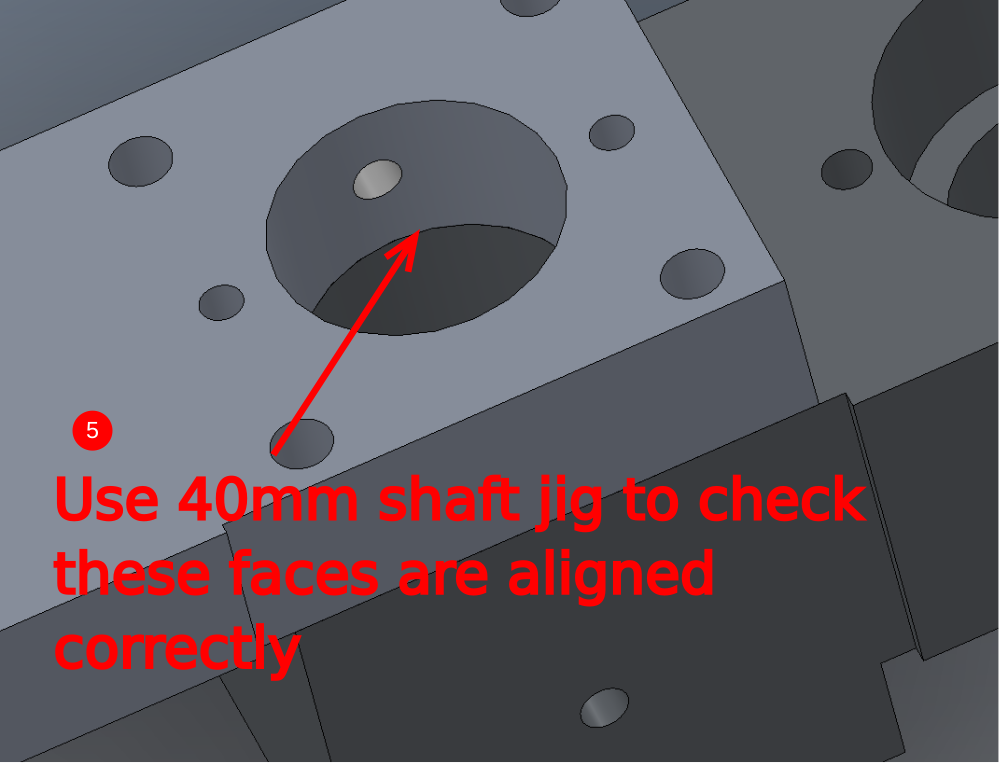
5 Check with 40mm shaft jig that alignment is correct and shaft can pass through assembled 40mm bore

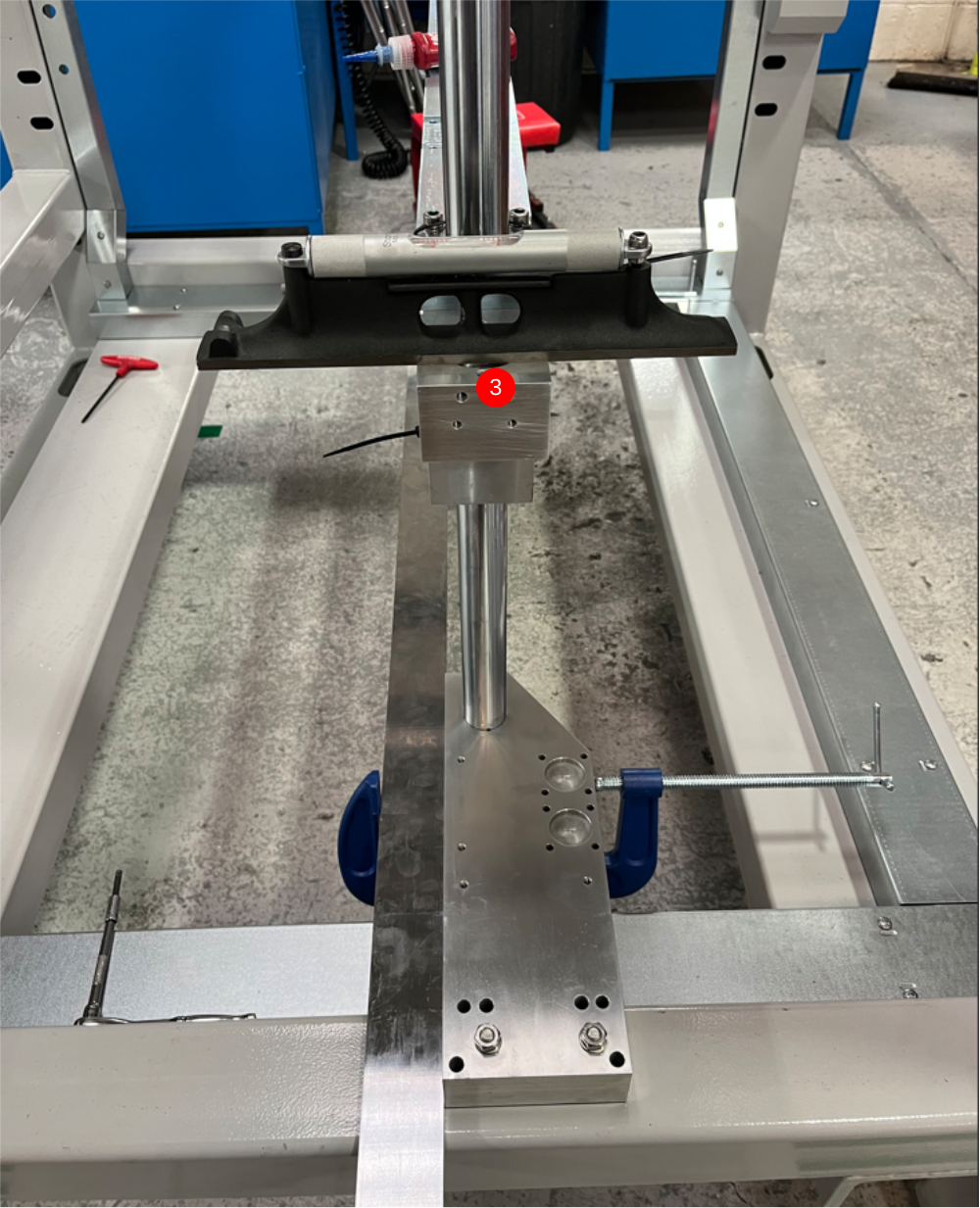
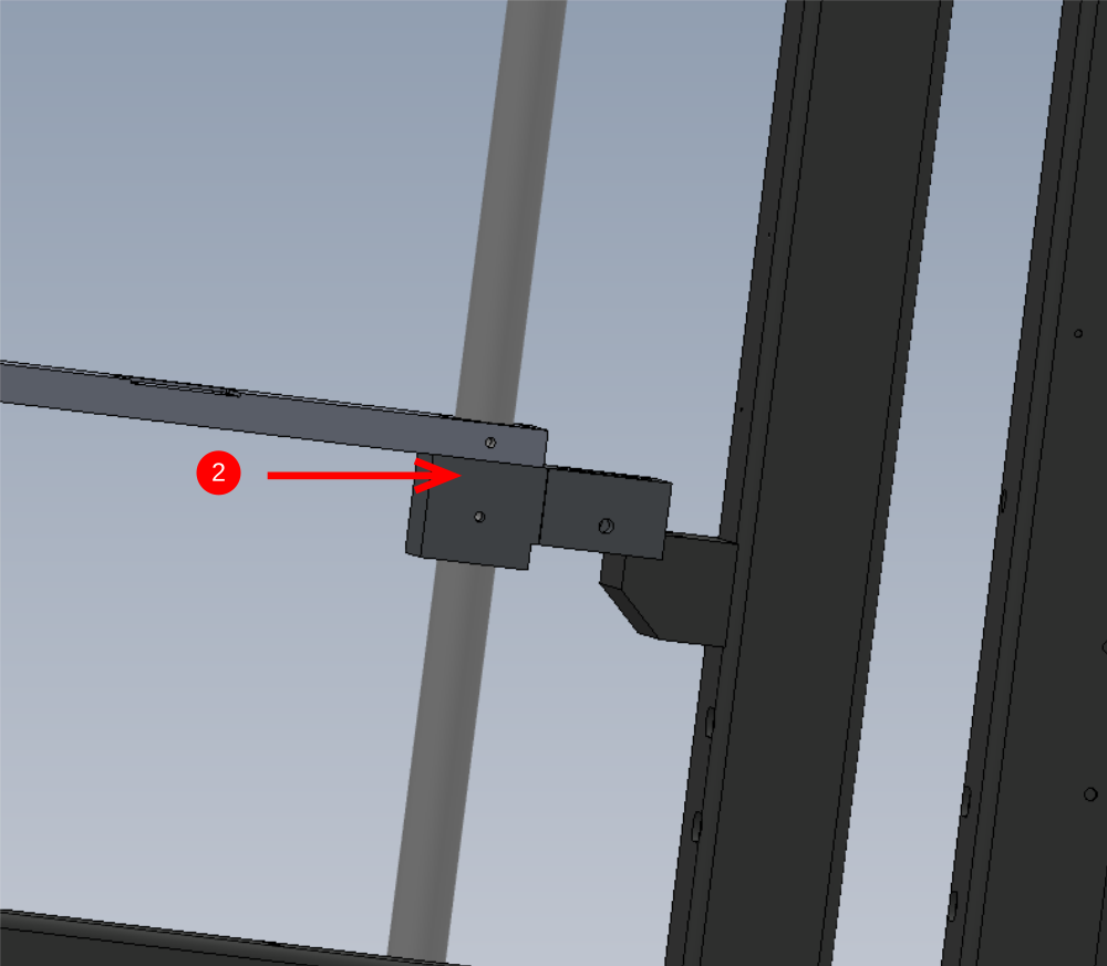
Étape 7 - Fit Centre platform
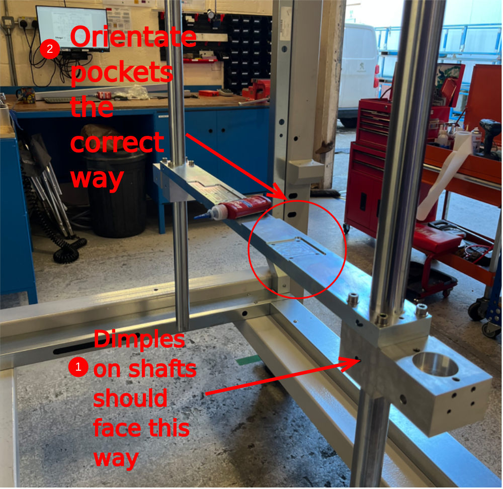
1 Ensure2 off dimples on each main vertical shaft are facing the rear of the machine
2 Slide into position centre platform assembly ensuring the correct orientation is achieved in regards to Machined pockets on the centre platform
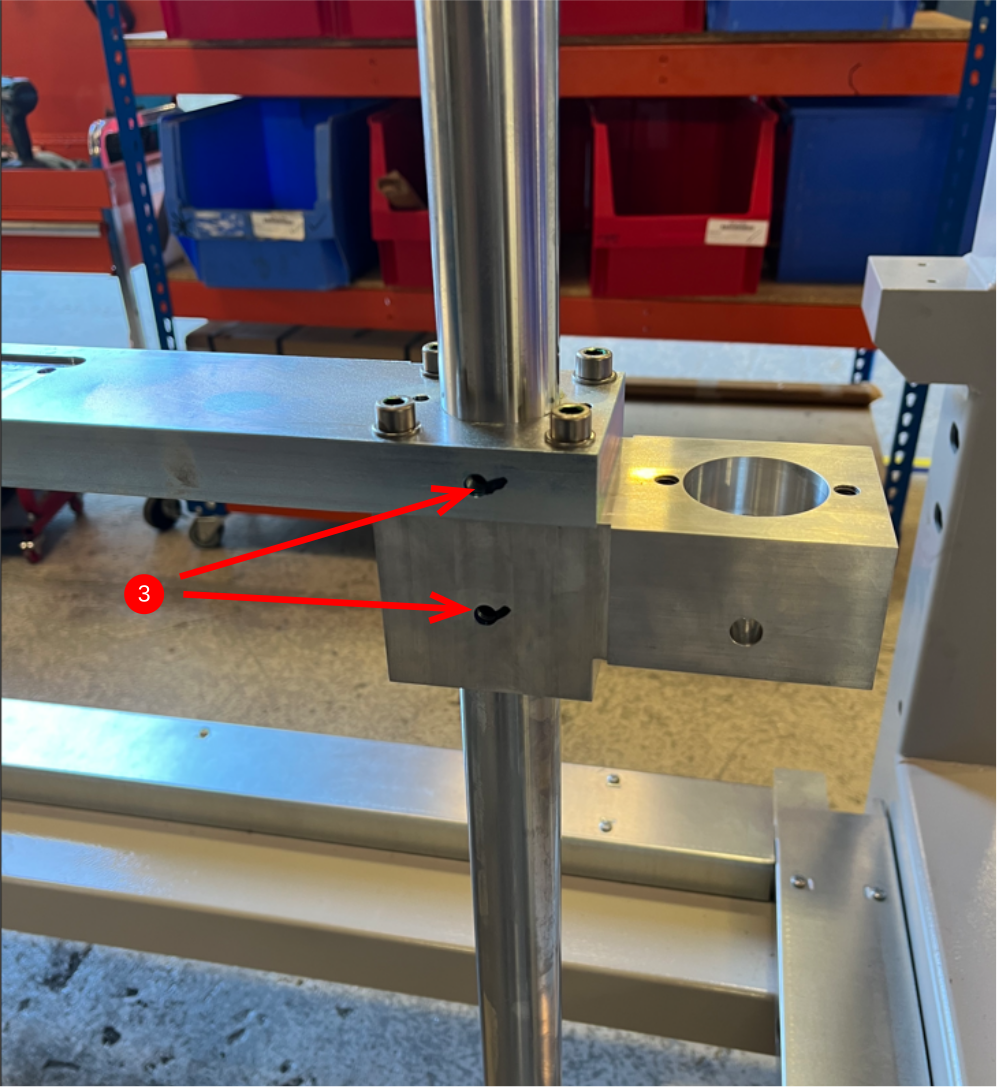
3 Align dimples to M8 tapped holes in crossmember and fix with 4 off M8 x 16 kcp grubscrew
4 Fit 2 off bearing block from R0015296 Bench Assemble bearings Assemblies as shown. Blocks should be orientated as previous fitted upper blocks


Étape 8 - Fit lower beam mounts
Fit
D0007683 Lower Beam Mount x 1
D0007684 Lower Beam Mount - Mirror x 1 as shown
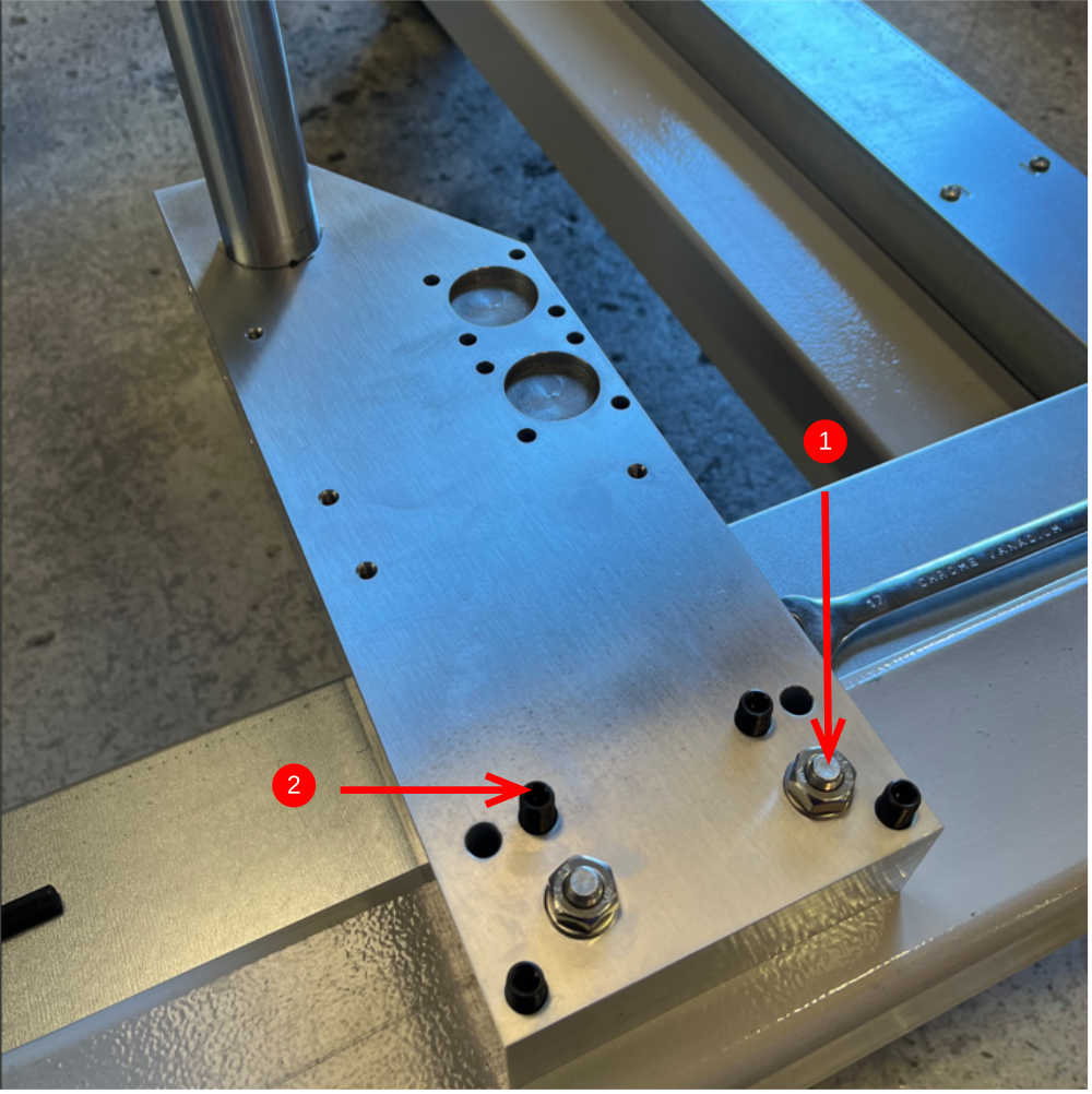
1 Use M10 x 70 socket caps , A form washers and standard M10 nuts to fix as shown
2 Insert 4 off M10 x 30 flat bottomed jacking grubscrew as shown

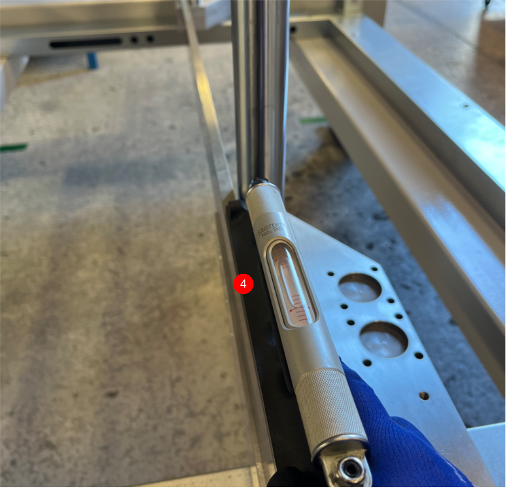
Étape 9 - Level lower beam mounts
1 Apply Medium tension to M10 socket caps and wind down M10 jacking grubscrews to touch on frame
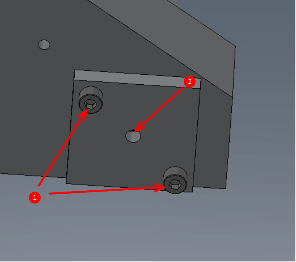
2 Level X axis of block using pair A or B, never use all 4
3 Level Y axis of block using pair A or B, never use all 4
Repeat for other side
4 Level across beam mounts using 2 meter straight edge. Adjust lowest platform to correct any error . Always use all 4 jacking grubscrews turned exactly the same amount to raise platform to adjust
5 Once levelled, check no gaps are present on contact face of straightedge along both lower beam mounts


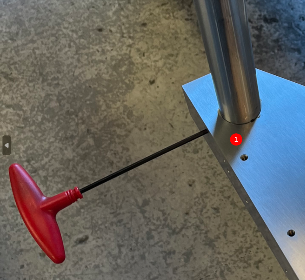
Étape 10 - Align lower beam mounts
1 Insert 1 off M8 x 16 kcp grubscrew per lower beam mount and apply light pressure with no adhesive
2 Release pressure on M10 socket caps that hold lower beam mounts in place
3 Use straight edge as indicated
4 Adjust lower beam mount position using level as indicated . Once level is achieved, apply light pressure to M10 socket caps and repeat for other side
5 Adjust Lower beam mount position using a level as indicated . Repeat on other side
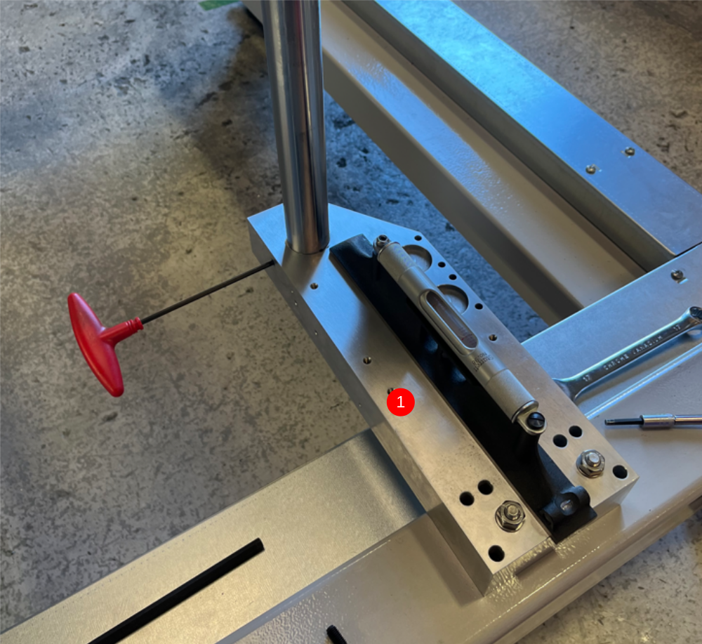
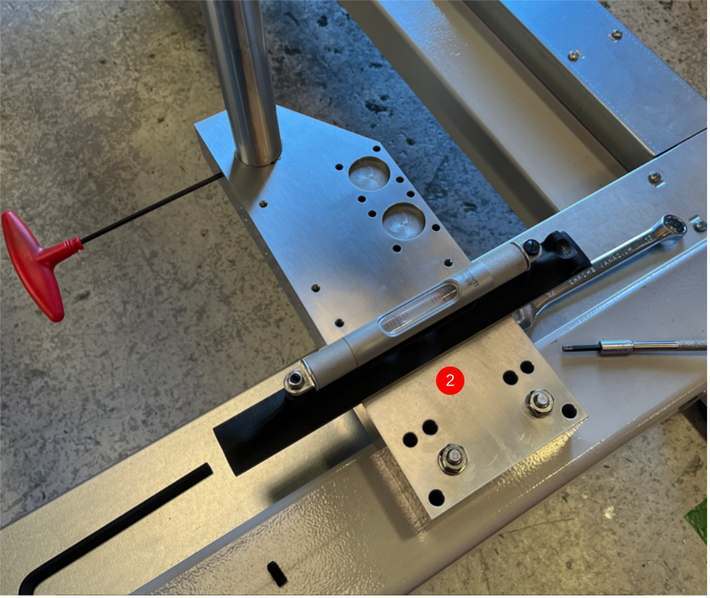
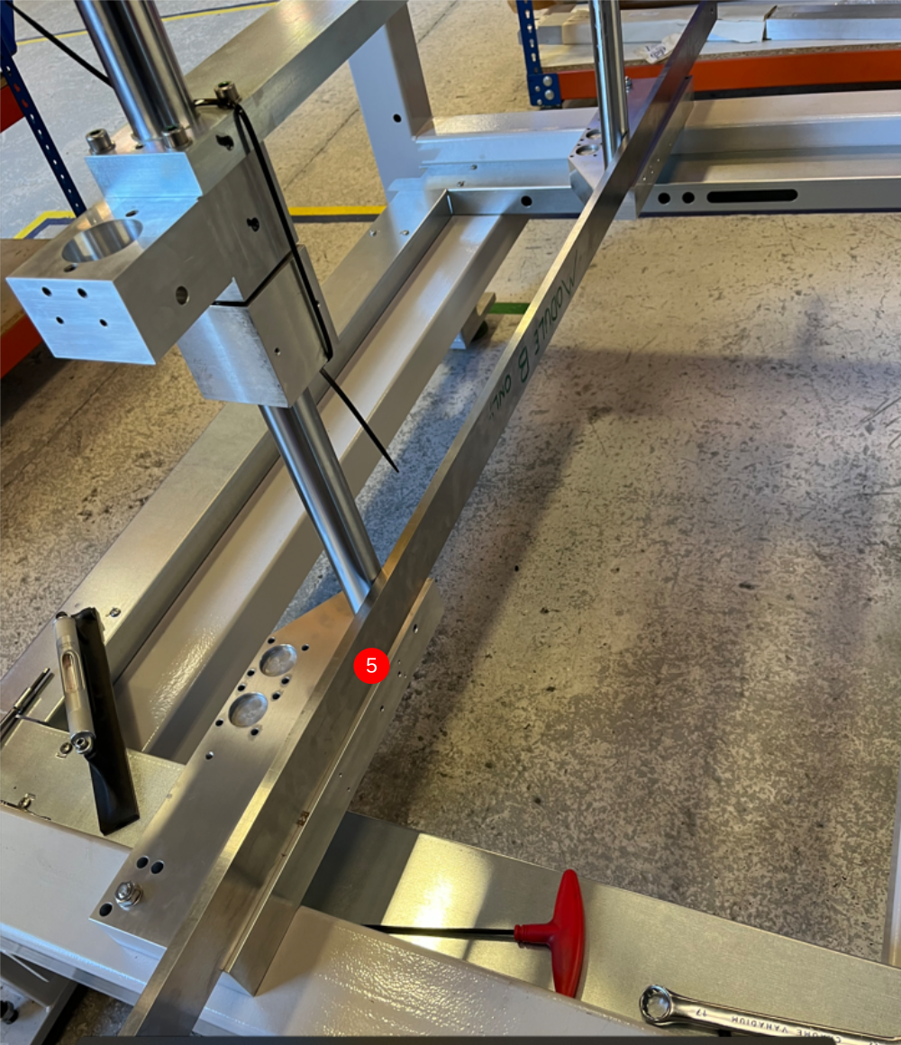
Étape 11 - Check shaft pitching
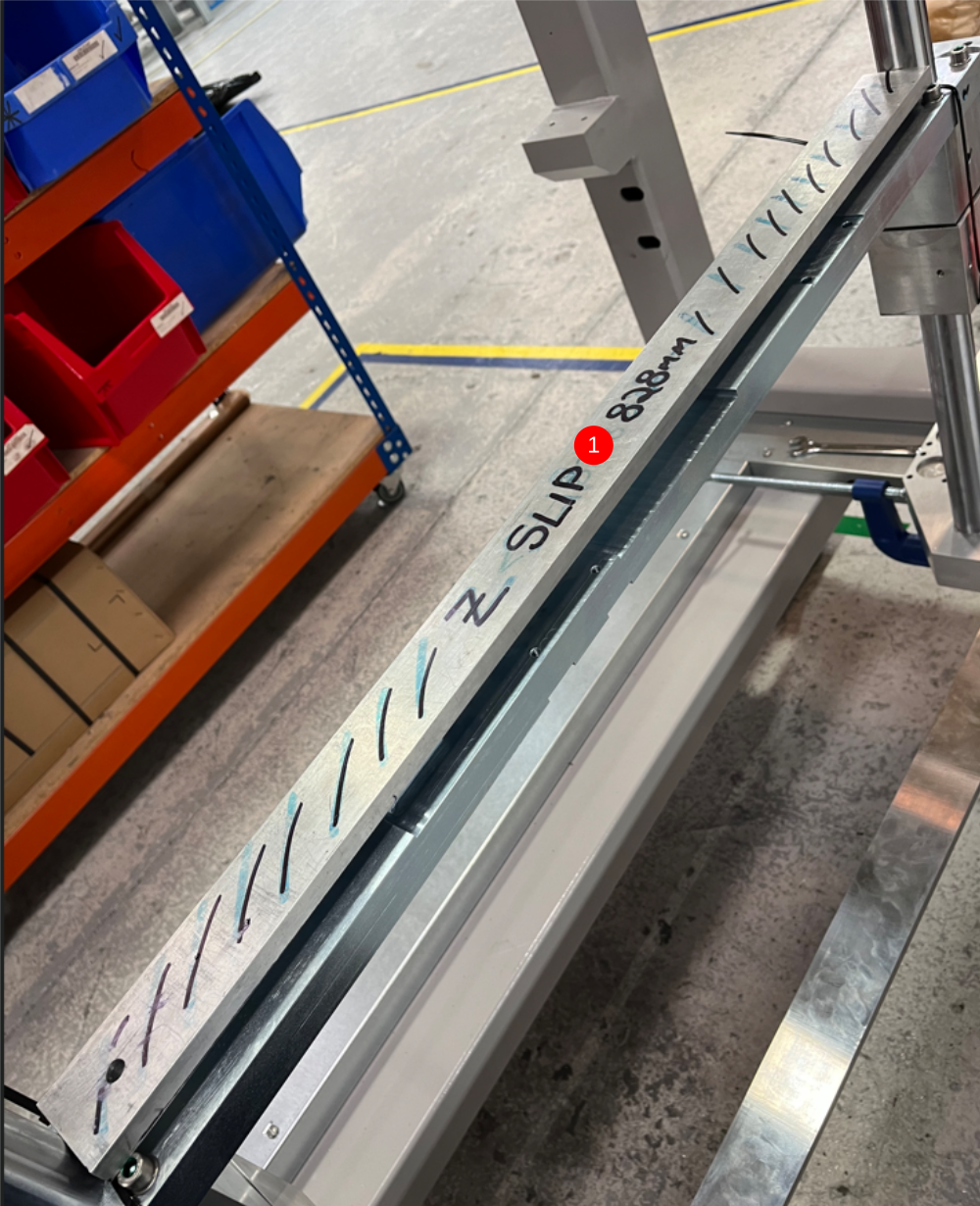
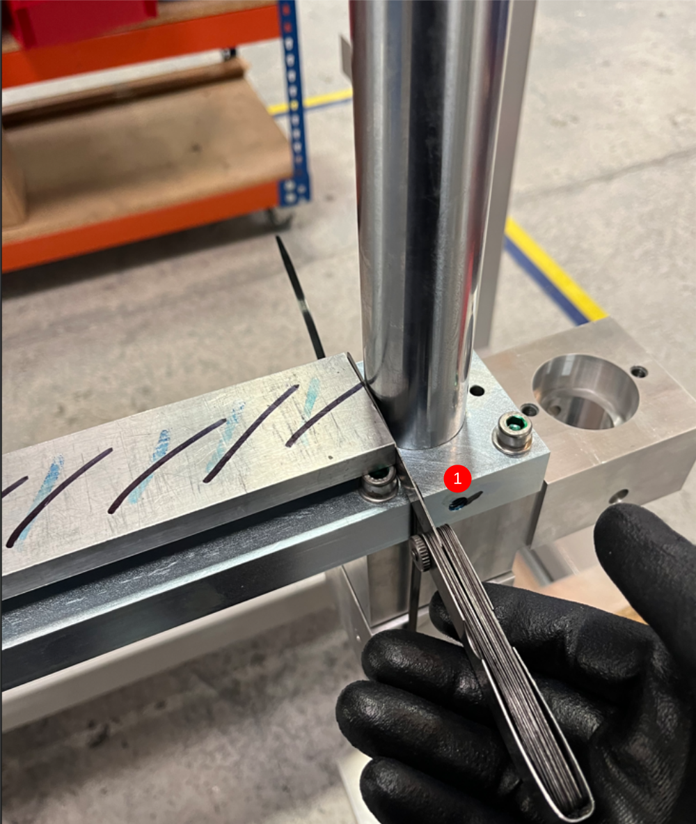
1 Use Z shaft slip gauge to measure pitch of shafts at upper point shown . Measure gap using feeler gauges
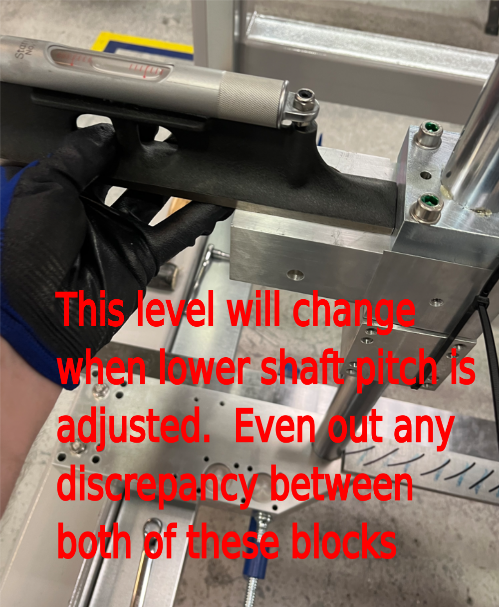
2 Check shaft pitching at lower point shown , this must be set to replicate upper measurement . Adjust lower beam mounts to adjust this measurement
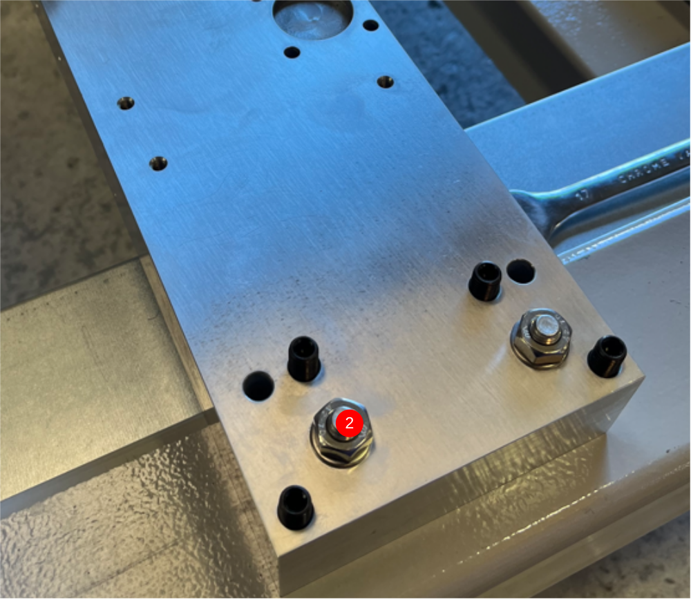
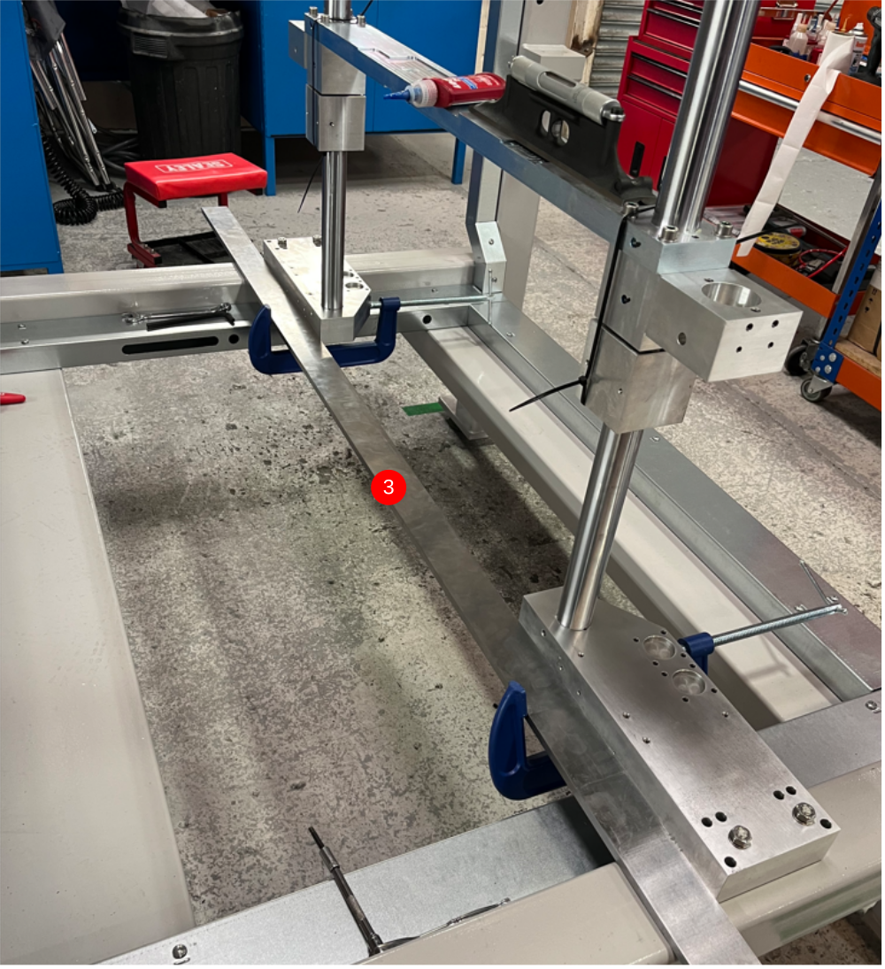
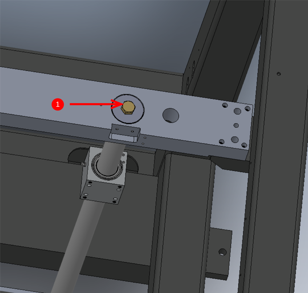
Étape 12 - Attach bottom plate
Attach 2 off D0000095 bottom plate as shown
1 Use 2 off M8 x 30 socket caps with A form washers to fix each plate .
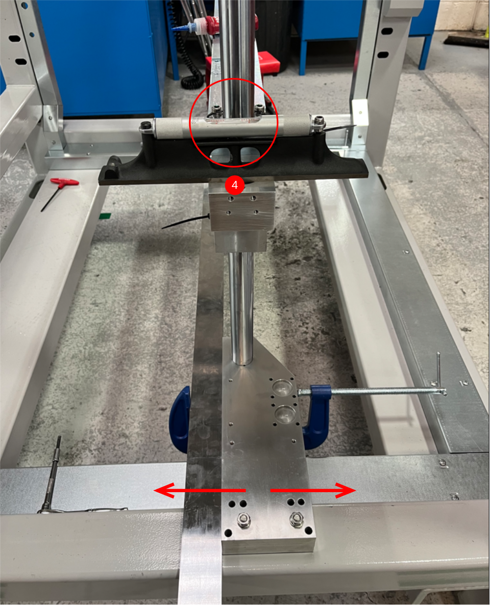
2 Use M8 x 70 Set bolt with standard M8 nut and A form washer in central hole
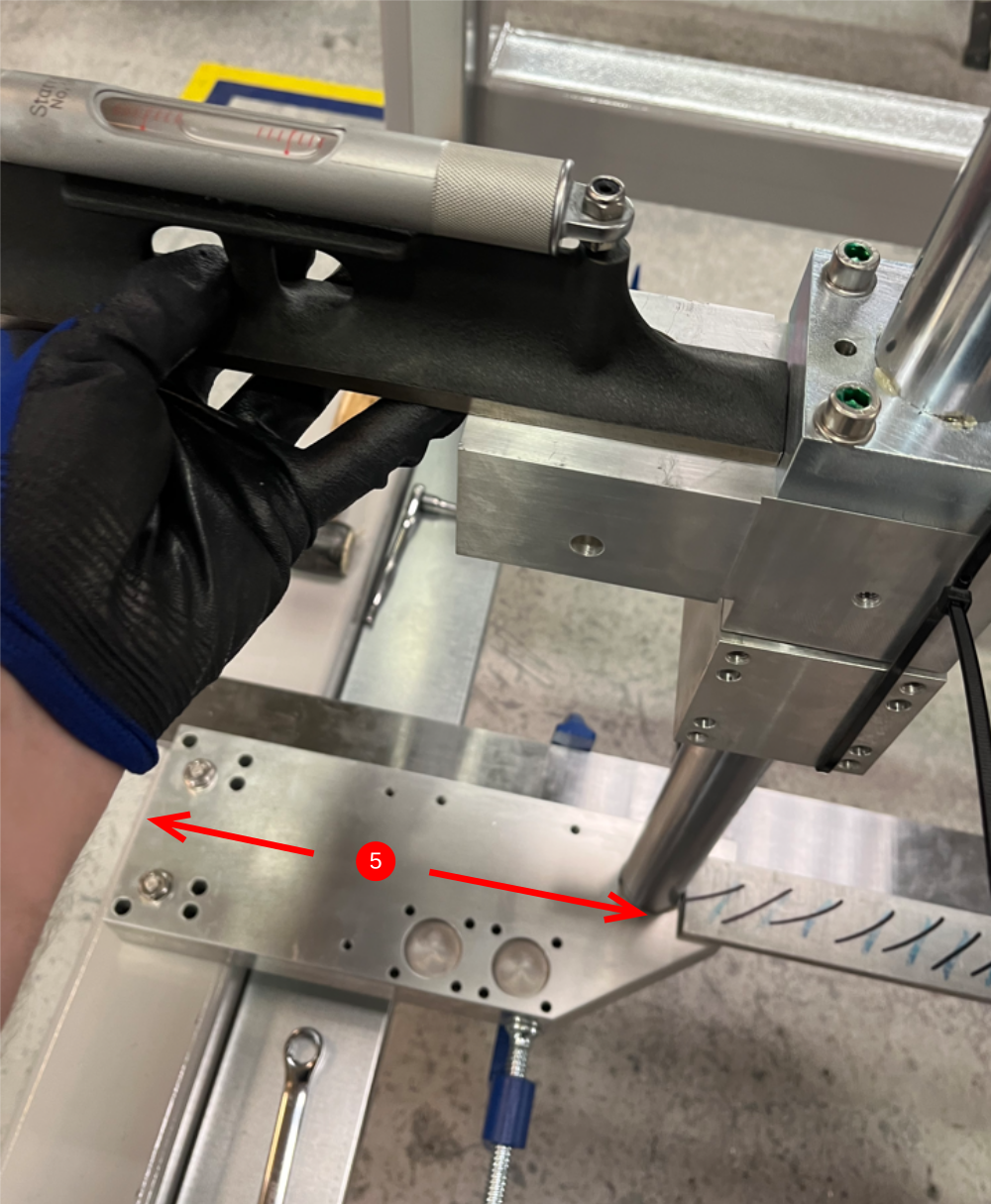
3 Tension M8 nut only when level is on top of plate above so no movement occurs


Étape 13 - Quality check
Check the following points
1 Level Check
2 Level check
3 Level check
4 Level check
5 Alignment and Level check
6 Alignment check

Étape 14 - Quality check
Check the following
1 Z shaft M16 set bolts are glued and finalised
2 4 off Grubscrews are finalised
3 2 off grubscrews are finalised
4 M10 socket caps are finalised


Étape 15 - continue to part 2 of dokit
Draft
 Français
 English
 Deutsch
 Español
 Italiano
 Português