Pneumatic installation details for ZX5 module B

Difficulté
Difficile
Durée
1 minute(s)
Sommaire
- 1 Introduction
- 2 Étape 1 - Unless otherwise stated
- 3 Étape 2 - Connect Air service unit
- 4 Étape 3 - Connect Air gun
- 5 Étape 4 - Flow reg directions
- 6 Étape 5 - Finalise Y395 Connections
- 7 Étape 6 - Flow reg directions
- 8 Étape 7 - Y386 connections
- 9 Étape 8 - Y351 and Y270 connections
- 10 Étape 9 - Y360 connection
- 11 Étape 10 - Fit Quick exhaust valves to Z supports
- 12 Étape 11 - Assemble V cut valve
- 13 Étape 12 - Mount to cross beam
- 14 Étape 13 - Connect Y389
- 15 Étape 14 - Y389 cylinder connections
- 16 Étape 15 - Fit rear lower panel
- 17 Commentaires
Introduction
Tools Required
Pipe cutters
Pipe identification numbers
Parts Required
D0015703 Air Gun Bracket x 1
P0000010 Elbow Adaptor 6mm - 1/8 BSPT (Taper thread) x 2
P0000046 Fitting: 'Y' Adaptor 6mm x 4
P0000053 6mm T (P16) x 2
P0000075 Parallel Y Connector 8mm x 1
P0000077 Straight Adaptor 8mm - 1/8BSP x 3
P0000160 Fitting: Flow Controller In Line 6mm x 4
P0000161 Plug-in Reducer 6mm Tube 8mm Fitting x 6
P0000401 6mm inline non return valve x 2
P0000470 Valve: 5/2 PnPnu 1/8BSP x 1
P0000513 Ball valve with QS connector x 1
P0000551 6mm inline Quick Exhaust Fitting x 6
P0001106 Plug in reducer 12mm to 8mm x 7
P0001107 12mm Y connector x 8
R0015114 Bench Assemble Valve banks and RegulatorsÉtape 1 - Unless otherwise stated
Use Loctite 243 on all fasteners
Use Loctite 572 on all threaded pneumatic connection
Pen mark all fasteners to show finalised

Étape 2 - Connect Air service unit
Connect 2 off 12mm red and 1 off 12mm blue pipes as shown to air service unit

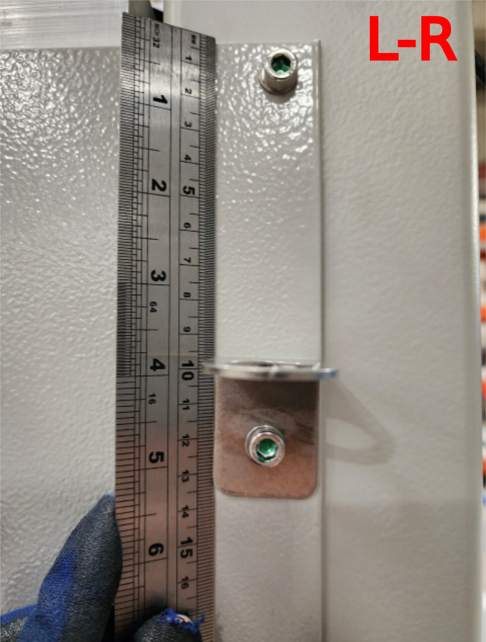
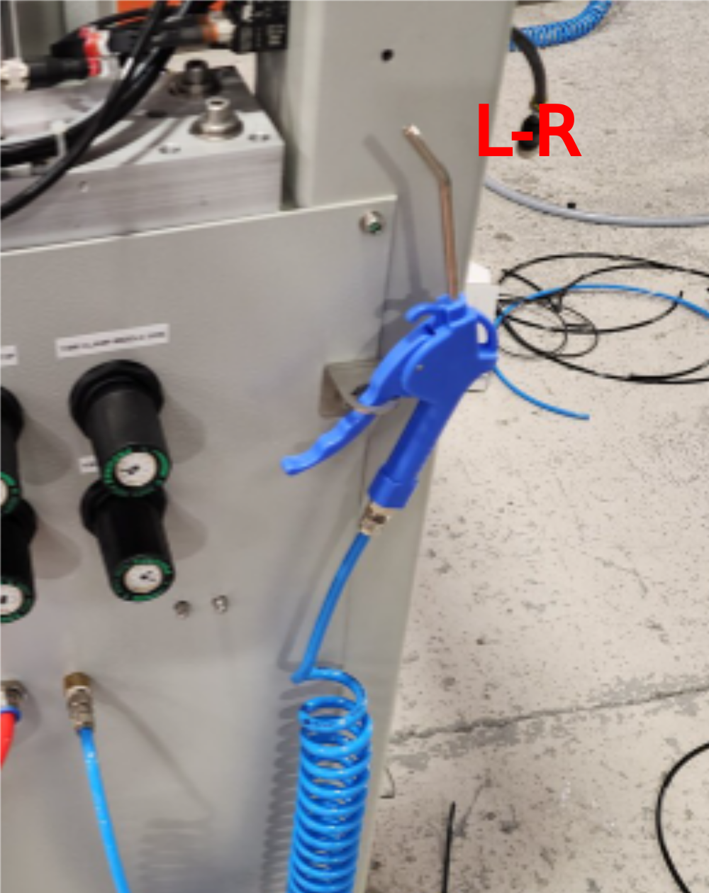
Étape 3 - Connect Air gun
Drill hook hole centre 120mm down at edge of panel. M6 tapped.
Attach bracket D0015703 for airgun and insert airgun
Étape 4 - Flow reg directions
Please ensure flow regulators are installed in the correct orientation
Please refer to diagram for correct installation

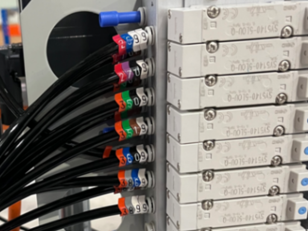
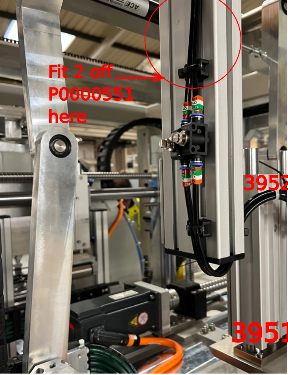
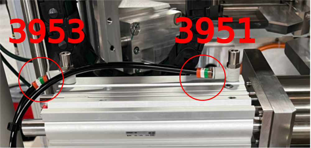
Étape 5 - Finalise Y395 Connections
Use P0000053 6mm tee to split 3951 pipe as shown
Run 3952 to top clamp
Run 3953 to side clamp
Use 2 off P0000160 flow regs to control flow as shown for top clamp
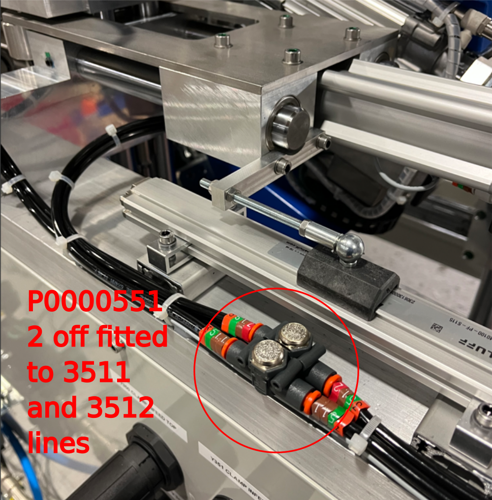
Use 4 off P0000551 quick exhaust valves, ensuring fitted before flow regulation
Incorporate 2 off reed switches into loom to connect to cylinders X111 Top clamp home and X112 side Clamp home


Étape 6 - Flow reg directions
Please ensure flow regulators are installed in the correct orientation
Please refer to diagram for correct installation
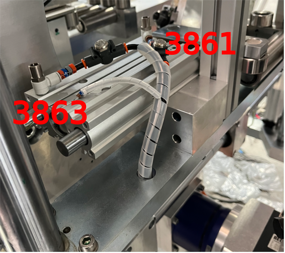
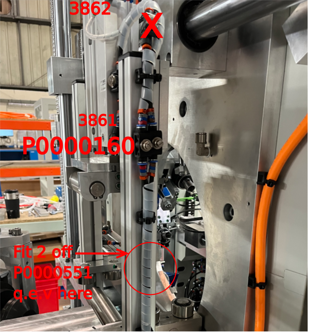
Étape 7 - Y386 connections
Spiral Wrap loom of 3861,3862 and 3863 pipes. Incorporate X59 and X61 reed switches into loom
Use P0000046 6mm Y connector to split3861 into 2 feed pipes
Loom 3861 and 3862 to top clamp with X59 reed switch
Loom 3861 and 3863 to side clamp with X61 reed switch
Utilize cable tie points as shown
(pictures show L-R configuration )


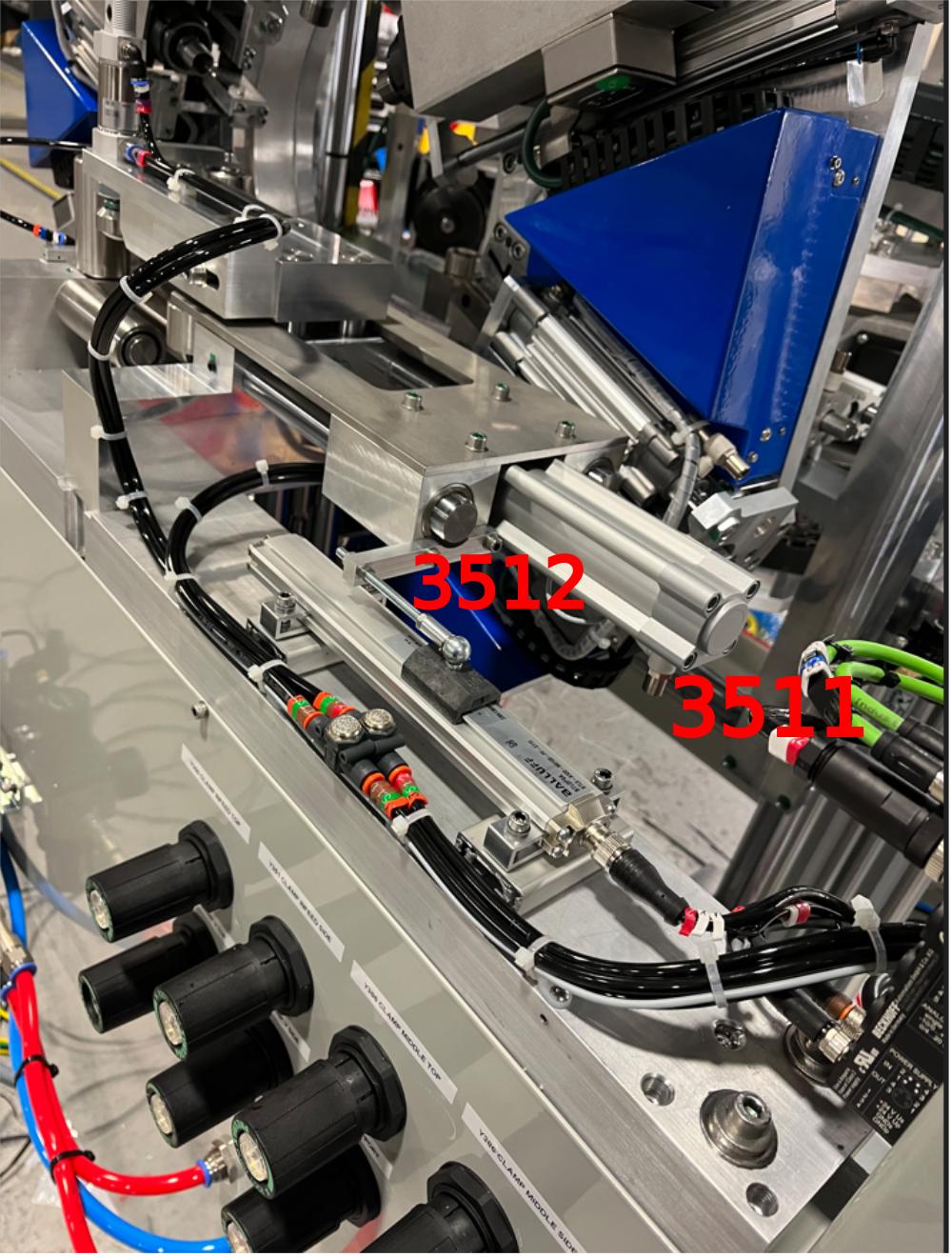
Étape 8 - Y351 and Y270 connections
Loom as shown
Incorporate X65 side clamp home reed switch into loom
ensure sufficient slack is left in looms to allow full range of movement


Étape 9 - Y360 connection
Route 3609 to roller blower as shown
Utilize pre fitted P0000160 flow reg


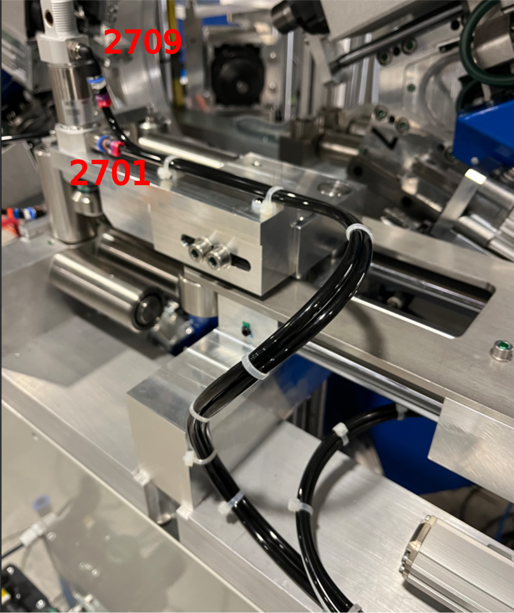
Étape 10 - Fit Quick exhaust valves to Z supports
Fit pre assembled quick exhaust valves to z supports as shown
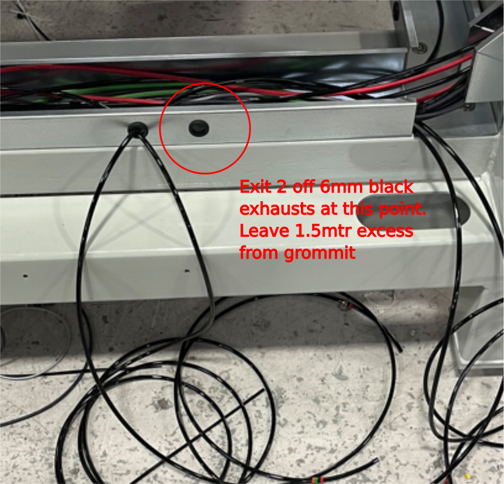
Connect additional 6mm black air pipe to each exhaust as shown and route to point shown at front of machine


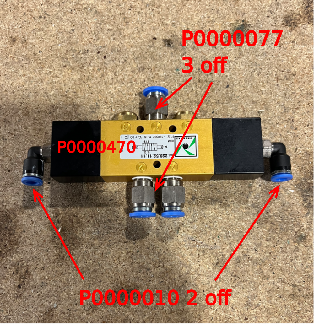
Étape 11 - Assemble V cut valve
Assemble P0000470 valve as shown
Étape 12 - Mount to cross beam
Drill and mount as shown valve to cross beam.
Fix with M4 x 30 socket caps and 2 off A form washers per Socket cap
Fit to cross beam next to 3891 and 3899 pipes exiting trunking


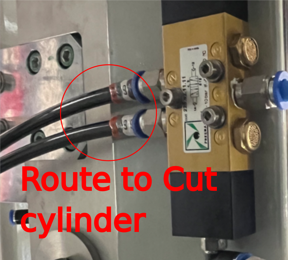
Étape 13 - Connect Y389
Connect 3891 and 3899 pipes as shown .
Connect 8mm blue connection to valve as shown
Route exit pipes 3891 and 3899 to cut cylinder

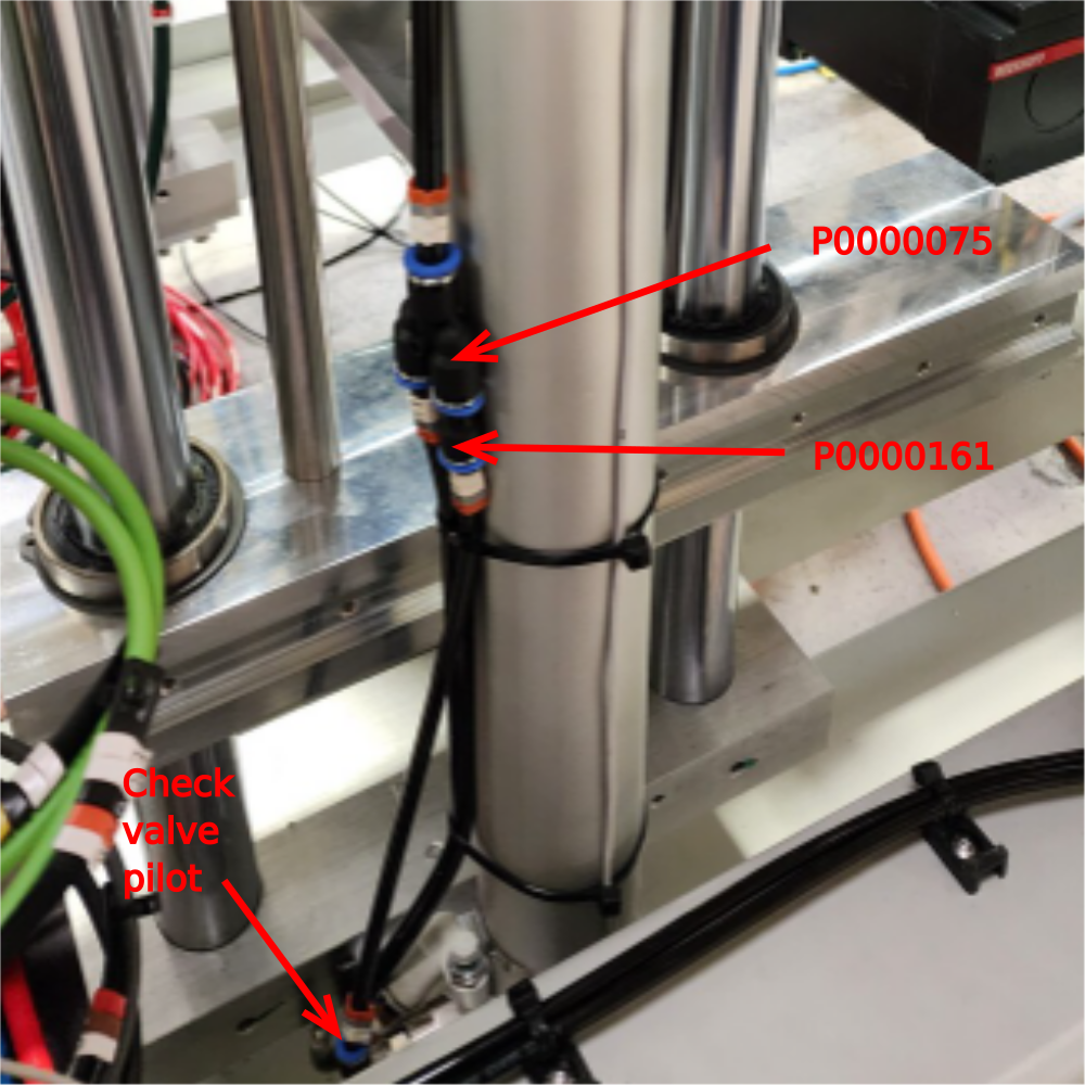
Étape 14 - Y389 cylinder connections
Split feed pipe 3899 as shown with 8mm Y connector
Use 8-6mm reducer and feed check valve at bottom of cylinder with 6mm pipe id 3899


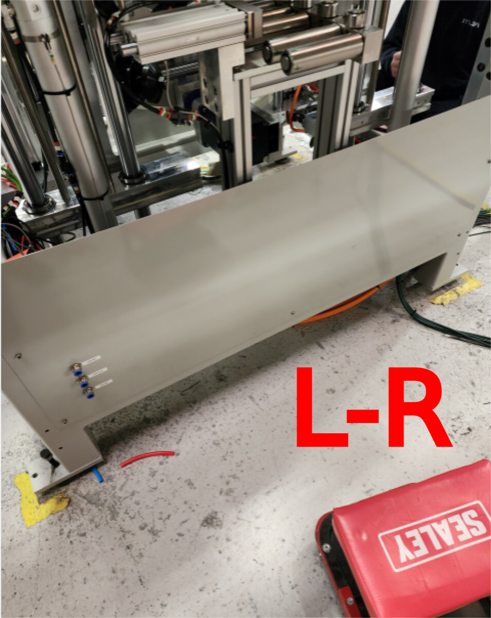
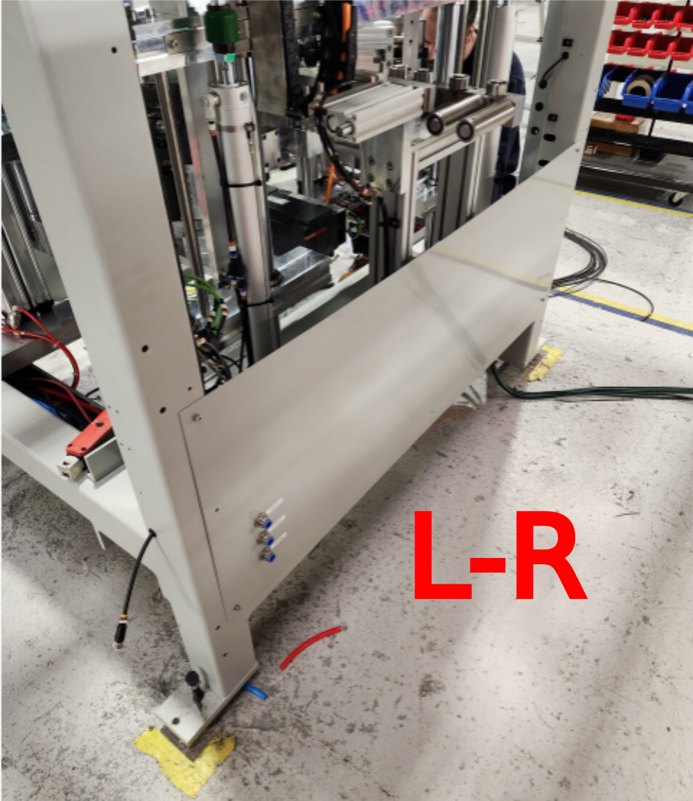
Étape 15 - Fit rear lower panel
Fit rear lower panel as shown, connecting 2 off 12mm red pipes and 1 off 12mm blue pipes to bulkhead connectors
Draft
 Français
 English
 Deutsch
 Español
 Italiano
 Português