Pneumatic installation details for ZX5 module B

Difficulté
Difficile
Durée
1 minute(s)
Sommaire
- 1 Introduction
- 2 Étape 1 - Unless otherwise stated
- 3 Étape 2 - Assemble Connection branch
- 4 Étape 3 - Run 1 off 12mm red pipe
- 5 Étape 4 - Run 1 off 12 Red air pipe
- 6 Étape 5 - Run 1 off 12 Red air pipe
- 7 Étape 6 - Run 2 off 8mm red pipes to front panel
- 8 Étape 7 - Run 1 off 6mm red air pipe to front panel
- 9 Étape 8 - 6mm red connections to pilot check valves
- 10 Étape 9 - Connect 2 off 6mm pipes to z support cylinders
- 11 Étape 10 - 8mm red V cut support cylinder connection
- 12 Étape 11 - Fit pre assembled lower front pneumatic panel
- 13 Étape 12 - Connect 12mm pipes
- 14 Étape 13 - Connect air gun feed
- 15 Étape 14 - Connect VZ regulator
- 16 Étape 15 - Connect Z support Regulator
- 17 Étape 16 - Connect Y386
- 18 Étape 17 - Connect Y351
- 19 Étape 18 - Connect Y350
- 20 Étape 19 - Connect Y395
- 21 Étape 20 - Check Connection for air gun
- 22 Commentaires
Introduction
Tools Required
Pipe cutters
Pipe identification numbers
Parts Required
D0015703 Air Gun Bracket x 1
P0000010 Elbow Adaptor 6mm - 1/8 BSPT (Taper thread) x 2
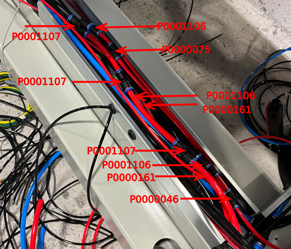
P0000046 Fitting: 'Y' Adaptor 6mm x 4
P0000053 6mm T (P16) x 2
P0000075 Parallel Y Connector 8mm x 1
P0000077 Straight Adaptor 8mm - 1/8BSP x 3
P0000160 Fitting: Flow Controller In Line 6mm x 4
P0000161 Plug-in Reducer 6mm Tube 8mm Fitting x 6
P0000401 6mm inline non return valve x 2
P0000470 Valve: 5/2 PnPnu 1/8BSP x 1
P0000513 Ball valve with QS connector x 1
P0000551 6mm inline Quick Exhaust Fitting x 6
P0001106 Plug in reducer 12mm to 8mm x 7
P0001107 12mm Y connector x 8
R0015114 Bench Assemble Valve banks and Regulators
Étape 1 - Unless otherwise stated
Use Loctite 243 on all fasteners
Use Loctite 572 on all threaded pneumatic connection
Pen mark all fasteners to show finalised

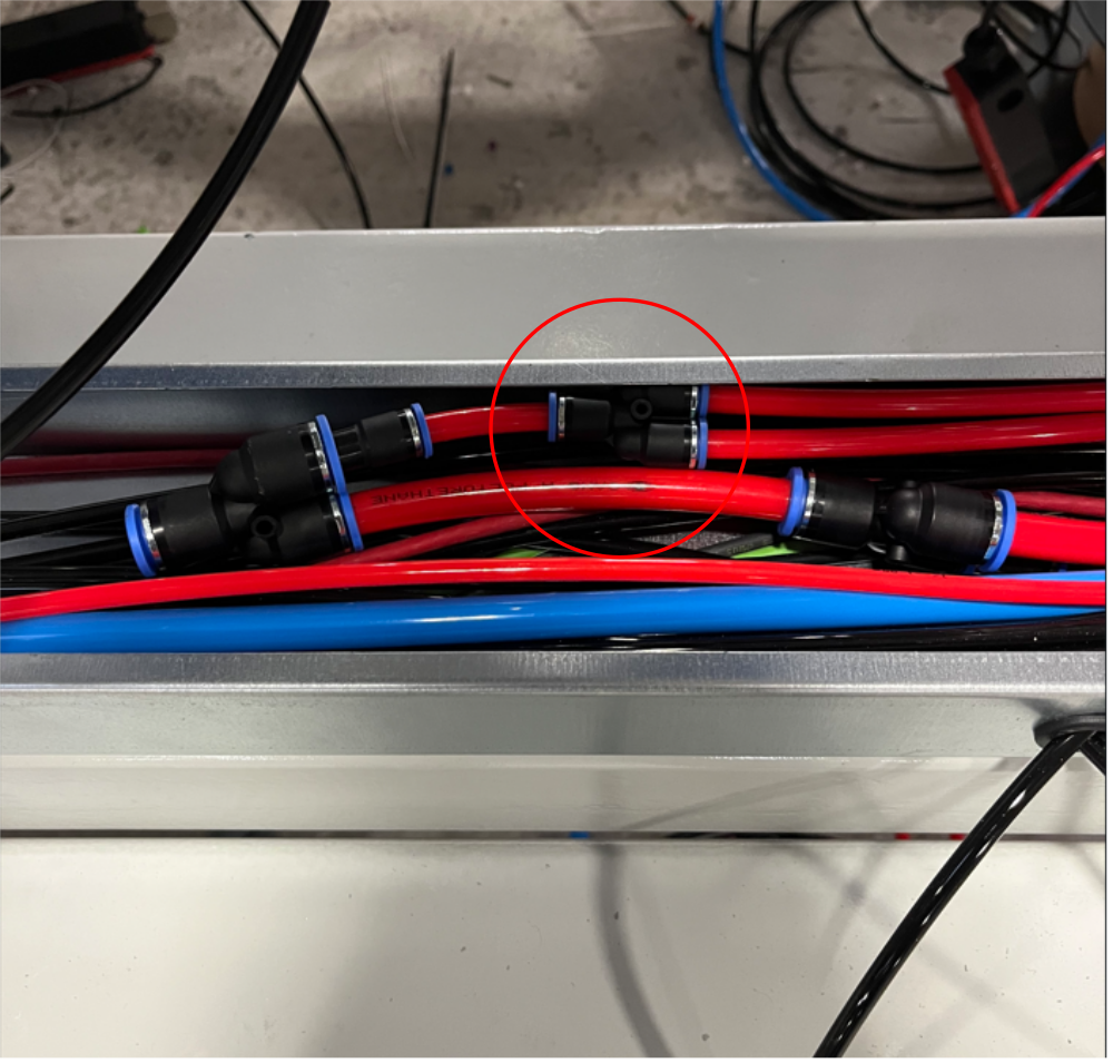
Étape 2 - Assemble Connection branch
Assemble connection branch as shown
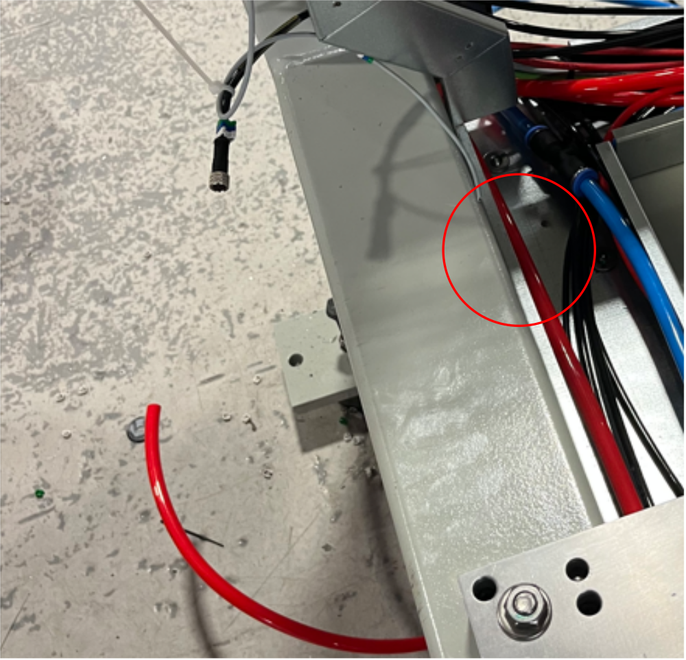
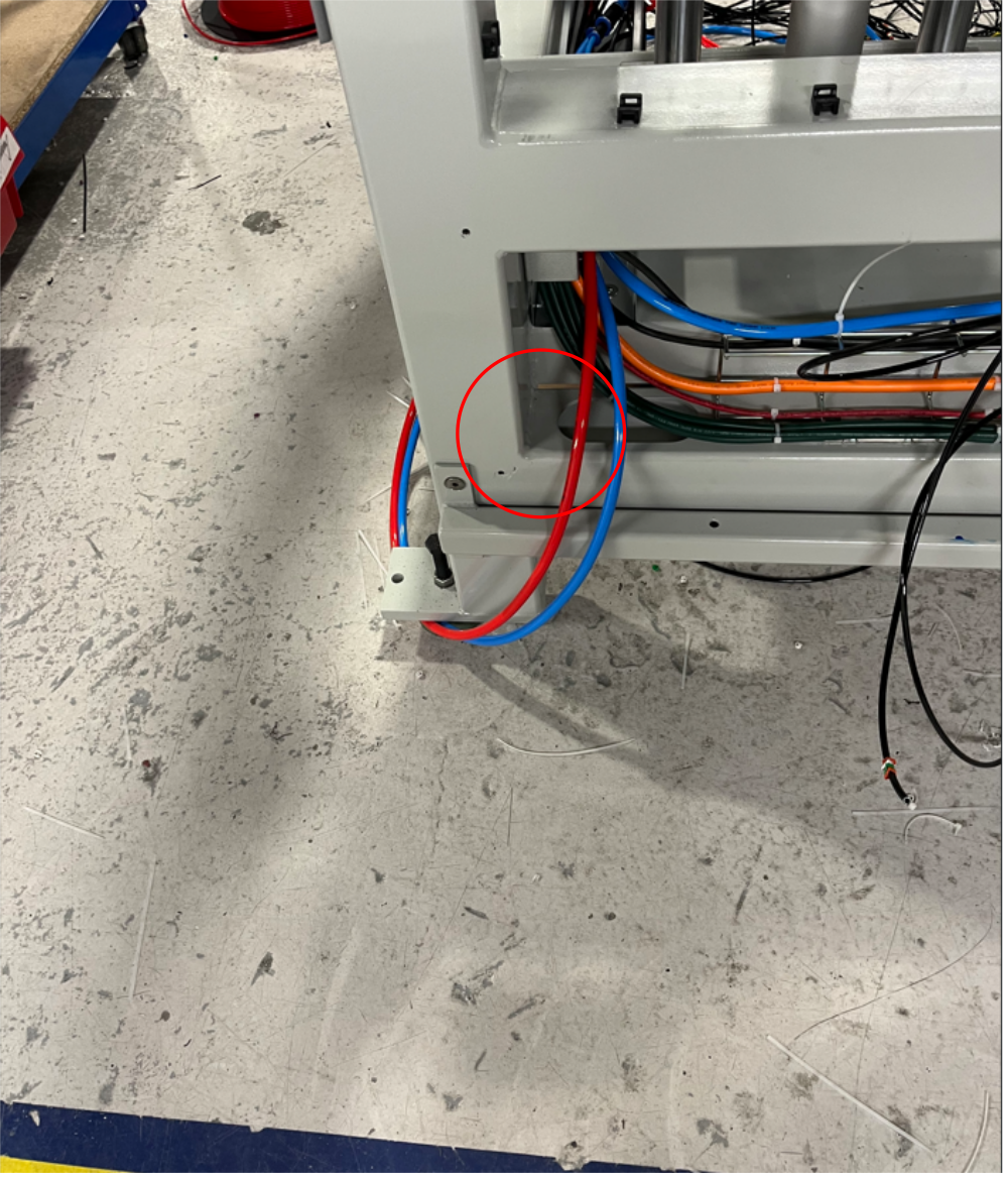
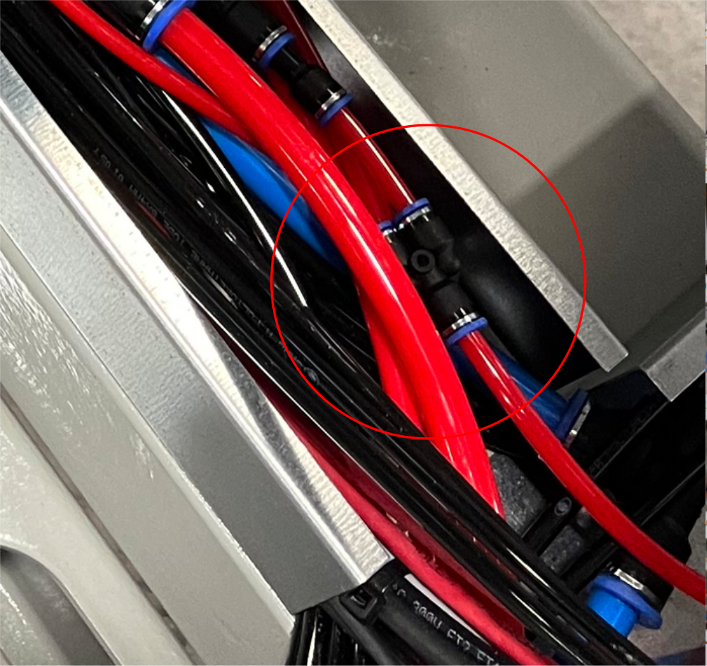
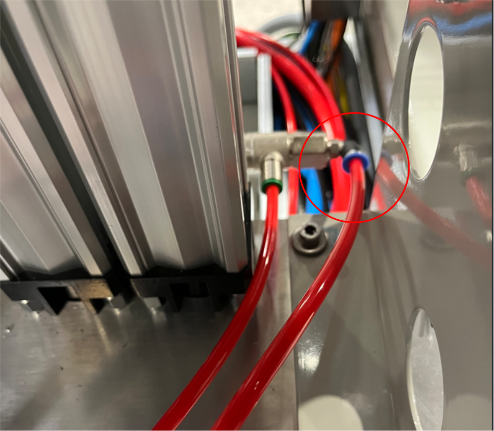
Étape 3 - Run 1 off 12mm red pipe
Run 1 off 12mm red pipe from 12 y connector to front panel as shown
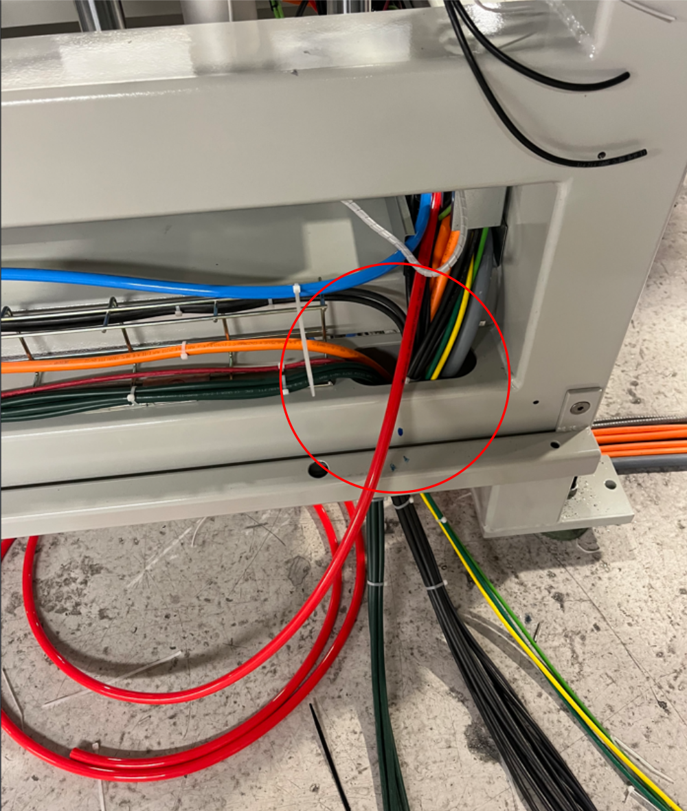
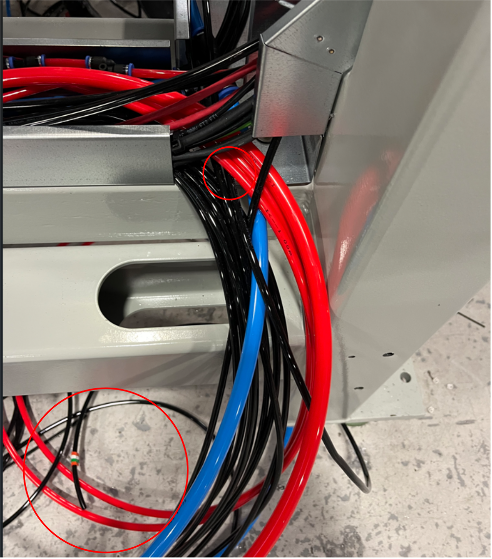
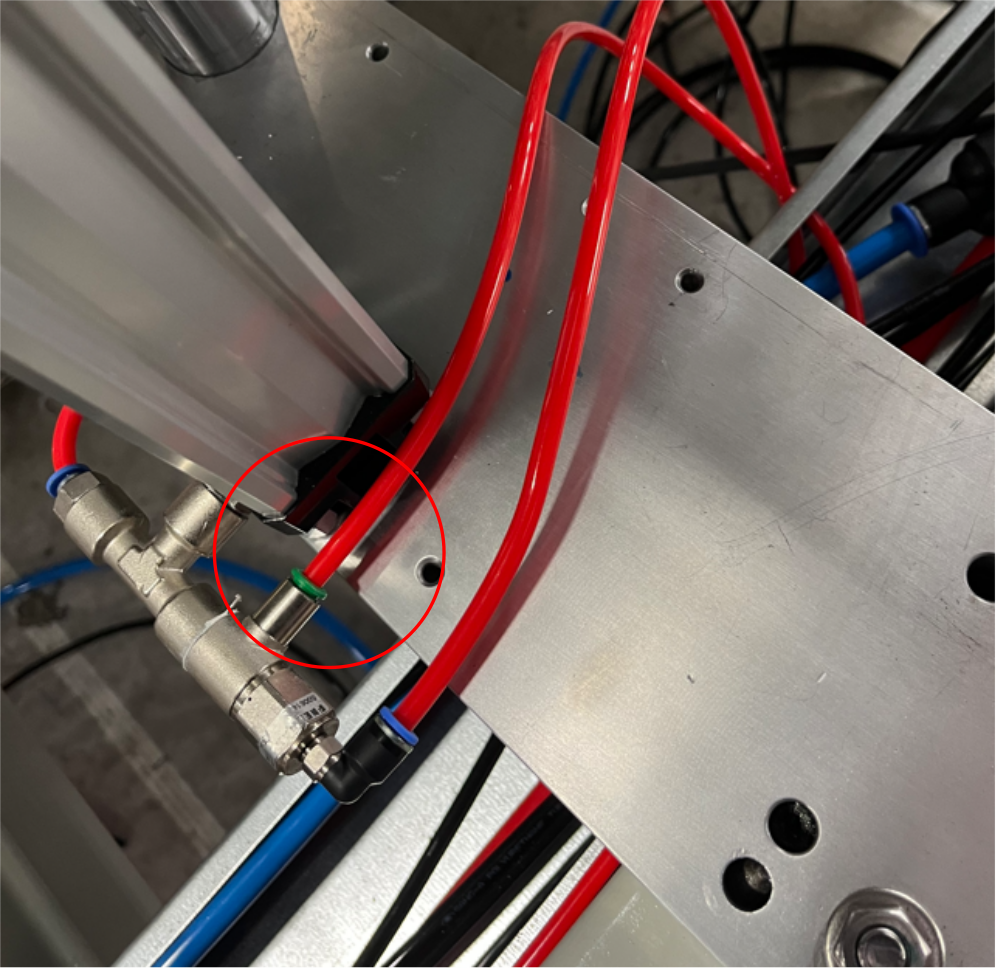
Étape 4 - Run 1 off 12 Red air pipe
Add 1 off 12 red air pipe to 12 y connector and route as shown leaving enough length once exited machine rear to carry across wire basket to rear pipe exit point
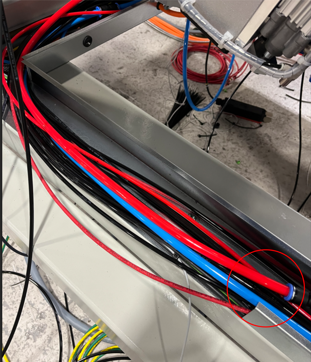
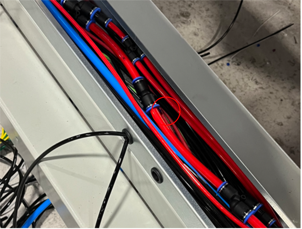
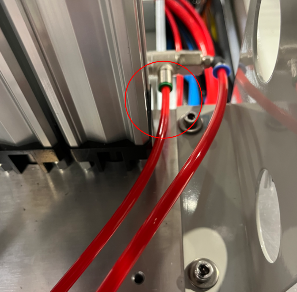
Étape 5 - Run 1 off 12 Red air pipe
Add 1 off 12 red air pipe to run front to back exit of machine as shown
Étape 6 - Run 2 off 8mm red pipes to front panel
Connect 2 off 8mm red pipes to 8mm y connector and run to front panel connection area
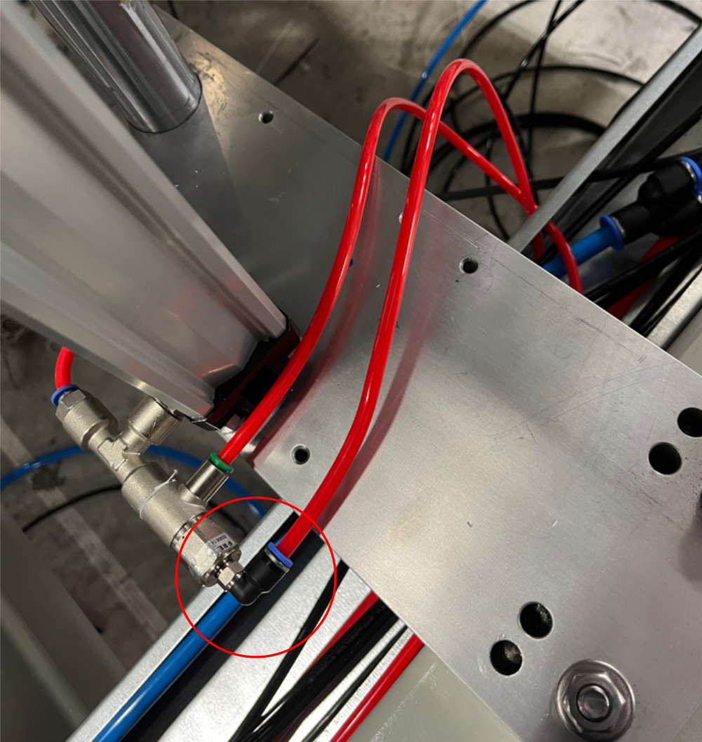
Étape 7 - Run 1 off 6mm red air pipe to front panel
Connect 1 off 6mm red air pipe to fitting shown and run to front panel
Étape 8 - 6mm red connections to pilot check valves
Run 2 off 6mm red pipes from indicate 6mm y connection and connect to z support pilot valves a shown
Étape 9 - Connect 2 off 6mm pipes to z support cylinders
Connect 2 off 6mm red air pipes to indicated fittings on Z supports and run to front panel connection point. Identify pipes as Z reg for connection later
Étape 10 - 8mm red V cut support cylinder connection
Connect 8mm red pipe to base of support cylinder (with exhaust at top of cylinder). Run to front panel connection and identify pipe as VZ reg

Étape 11 - Fit pre assembled lower front pneumatic panel
Fit pre assembled lower front panel
Use M6 x 16 5socket caps with M6 A form washers
Use 2 off M5 x 12 socket caps with M5 A form washers
Étape 12 - Connect 12mm pipes
Connect 2 off 12mm red and 1 off 12mmm blue air pipe to bulk heads

Étape 13 - Connect air gun feed
Connect 1 off unmarked 8mm red air pipe to air gun reg in port

Étape 14 - Connect VZ regulator
Connect 1 off unmarked 8mm red pipe to VZ support reg IN
connect 8mm pipe identified as VZ support to VZ support reg out

Étape 15 - Connect Z support Regulator
Connect unmarked 6mm red air pipe to Z support reg IN. Add P0000401 inline non return to line just before regulator. ensure non return valve is orientated as shown
Connect 2 off 6mm pipes identified as Z reg into P0000046 6mm y connector and then connect single pipe to Z support reg OUT

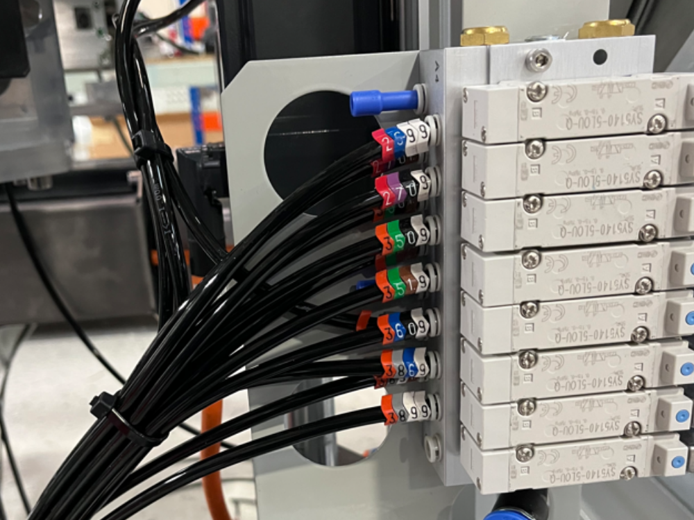
Étape 16 - Connect Y386
Connect 3862 To Clamp middle Top regulator OUT
Connect 3863 To Clamp middle Side OUT
Use P0000053 6mm tee connector to split feed of 3869 Pipe to feed both above regulators Port In

Étape 17 - Connect Y351
Connect 3519 to Clamp infeed side Regulator port IN
Connect 3512 to Clamp infeed side Regulator port OUT

Étape 18 - Connect Y350
Connect 3509 to Clamp Infeed top regulator port IN
Connect 3502 to Clamp infeed Top regulator port OUT

Étape 19 - Connect Y395
Connect 3952 to Clamp V top regulator Port OUT
Connect 3953 to Clamp V side regulator port OUT
Use P0000053 6mm tee connector to split feed of 3959 Pipe to feed both above regulators Port In

Étape 20 - Check Connection for air gun
Ensure Out port of air gun regulator is connected to bulkhead as shown

Draft
 Français
 English
 Deutsch
 Español
 Italiano
 Português