Pneumatic installation details for ZX5 module B

Difficulté
Difficile
Durée
1 minute(s)
Sommaire
- 1 Introduction
- 2 Étape 1 - Unless otherwise stated
- 3 Étape 2 - Assemble Connection branch
- 4 Étape 3 - Run 1 off 12mm red pipe
- 5 Étape 4 - Run 1 off 12 Red air pipe
- 6 Étape 5 - Run 1 off 12 Red air pipe
- 7 Étape 6 - Run 2 off 8mm red pipes to front panel
- 8 Étape 7 - 6mm red connections to pilot check valves
- 9 Étape 8 - 12mm red connection VZ support cylinder
- 10 Étape 9 - 12mm red connection Z support pilot 1
- 11 Étape 10 - 12mm red connection rear lower panel
- 12 Étape 11 - 12mm red connection 12mm from bulkhead
- 13 Étape 12 - 12mm red connection rear bulkhead
- 14 Étape 13 - Z support cylinder Feeds
- 15 Étape 14 - VZ support cylinder feed
- 16 Étape 15 - Z support exhaust
- 17 Commentaires
Introduction
Tools Required
Pipe cutters
Pipe identification numbers
Parts Required
D0015703 Air Gun Bracket x 1
P0000010 Elbow Adaptor 6mm - 1/8 BSPT (Taper thread) x 2
P0000046 Fitting: 'Y' Adaptor 6mm x 4
P0000053 6mm T (P16) x 2
P0000075 Parallel Y Connector 8mm x 1
P0000077 Straight Adaptor 8mm - 1/8BSP x 3
P0000160 Fitting: Flow Controller In Line 6mm x 4
P0000161 Plug-in Reducer 6mm Tube 8mm Fitting x 6
P0000401 6mm inline non return valve x 2
P0000470 Valve: 5/2 PnPnu 1/8BSP x 1
P0000513 Ball valve with QS connector x 1
P0000551 6mm inline Quick Exhaust Fitting x 6
P0001106 Plug in reducer 12mm to 8mm x 7
P0001107 12mm Y connector x 8
R0015114 Bench Assemble Valve banks and Regulators
Étape 1 - Unless otherwise stated
Use Loctite 243 on all fasteners
Use Loctite 572 on all threaded pneumatic connection
Pen mark all fasteners to show finalised

Étape 2 - Assemble Connection branch
Assemble connection branch as shown
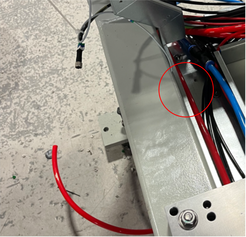
Étape 3 - Run 1 off 12mm red pipe
Run 1 off 12mm red pipe from 12 y connector to front panel as shown
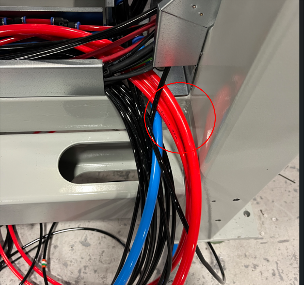
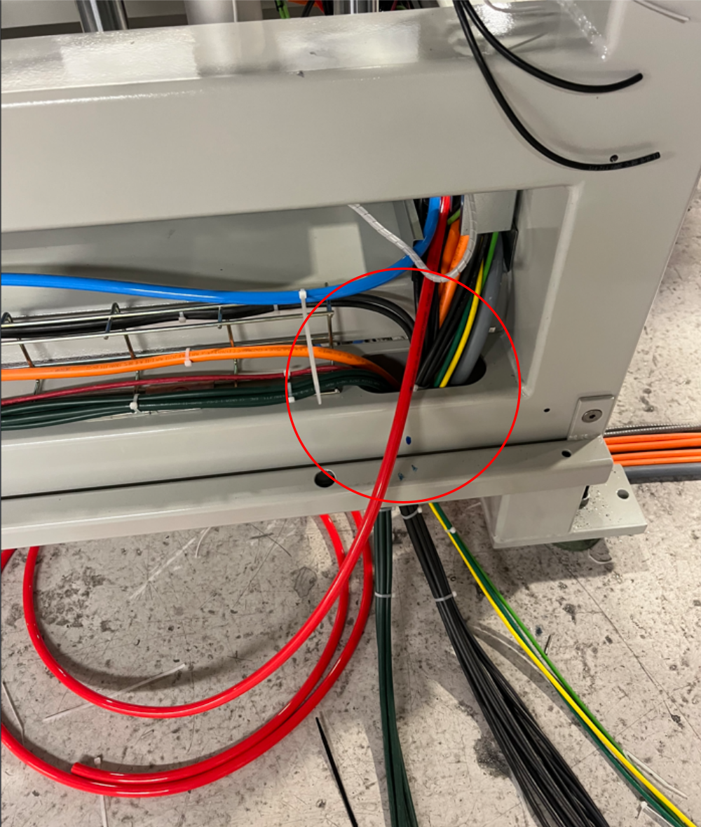
Étape 4 - Run 1 off 12 Red air pipe
Add 1 off 12 red air pipe to 12 y connector and route as shown leaving enough length once exited machine rear to carry across wire basket to rear pipe exit point
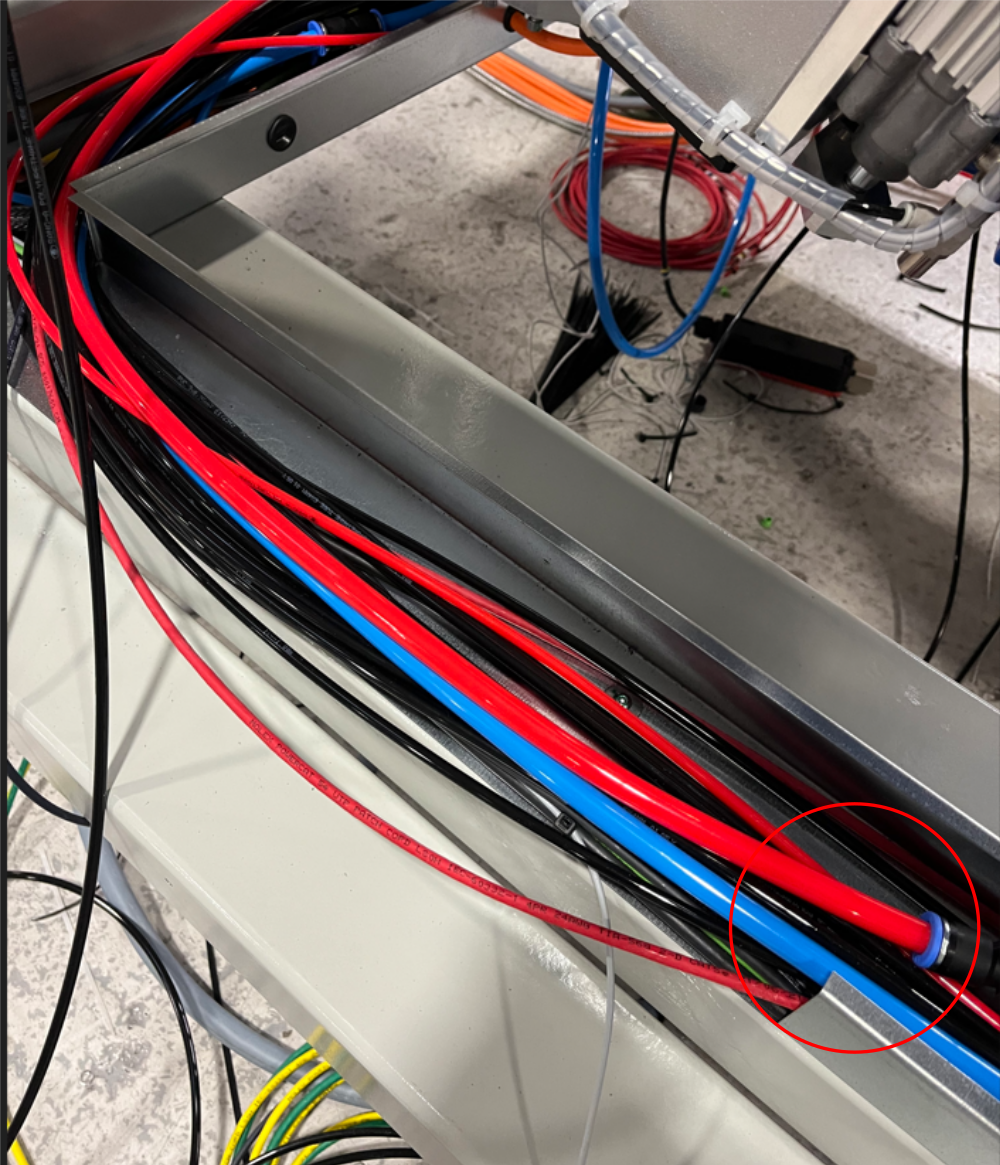
Étape 5 - Run 1 off 12 Red air pipe
Add 1 off 12 red air pipe to run front to back exit of machine as shown
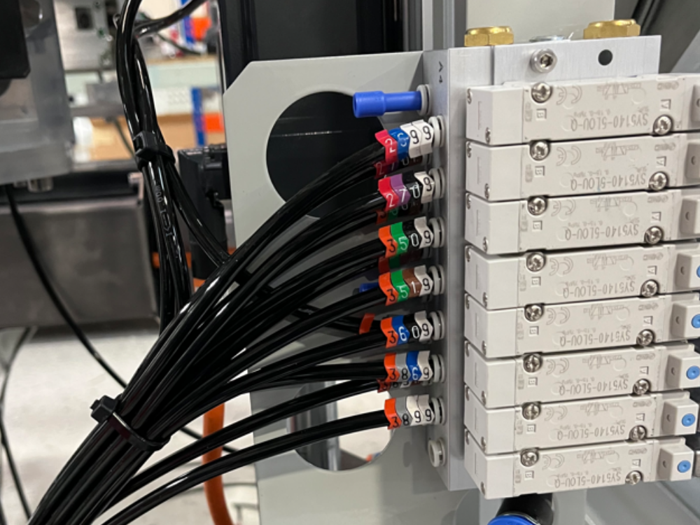
Étape 6 - Run 2 off 8mm red pipes to front panel
Connect 2 off 8mm red pipes to 8mm y connector and run to front panel connection area
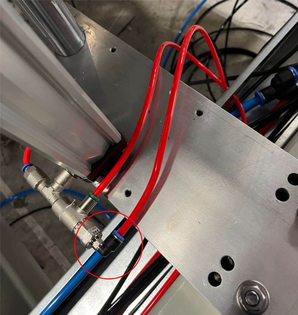
Étape 7 - 6mm red connections to pilot check valves
Run 2 off 6mm red pipes from indicate 6mm y connection and connect to z support pilot valves a shown
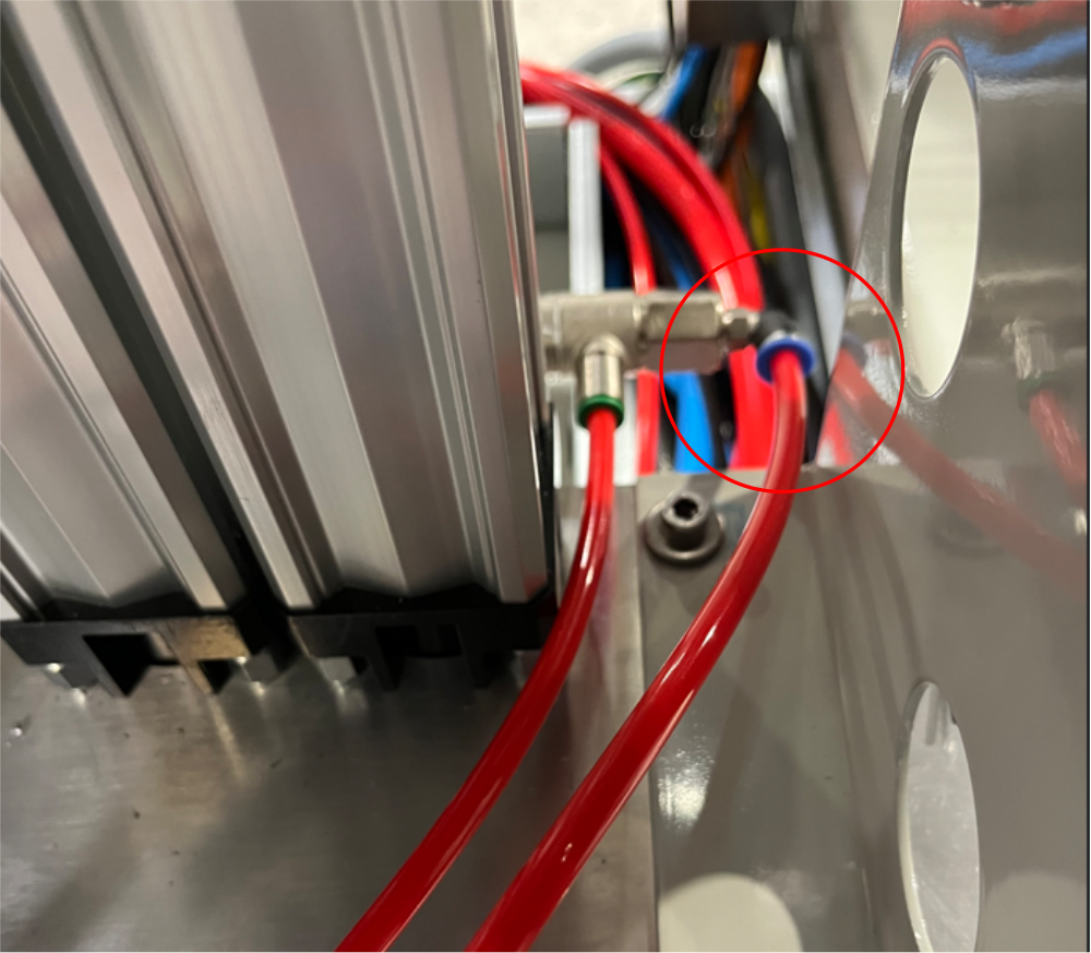
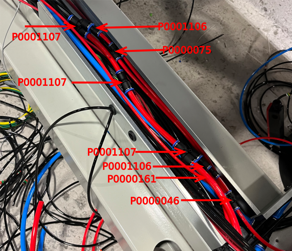
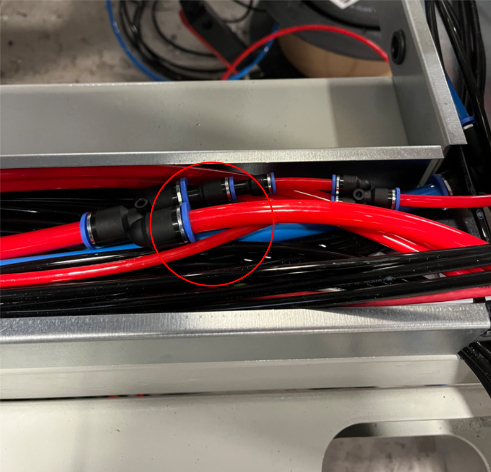
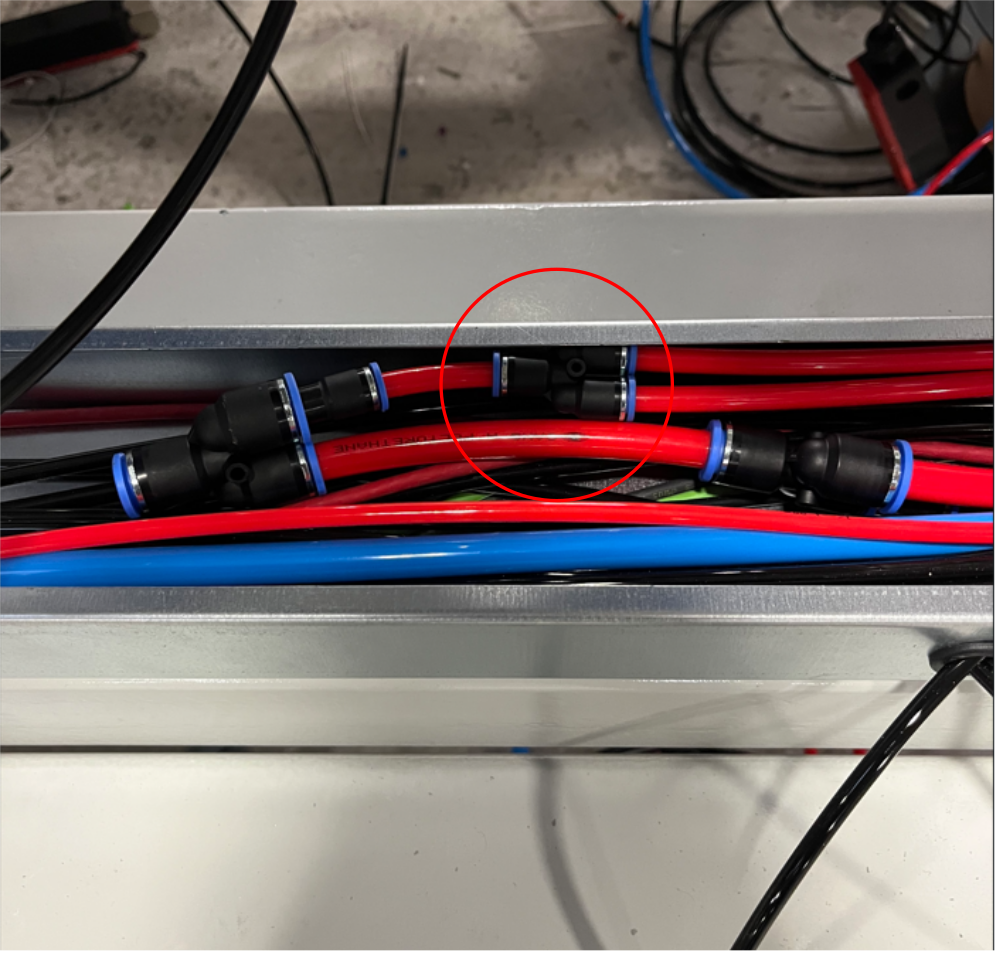
Étape 8 - 12mm red connection VZ support cylinder
Add 12mm Y connector at point indicated and connect to previous 12mm Y connector
Add 12mm to 8mm reducer and connect 8mm red pipe to feed VZ regulator port IN
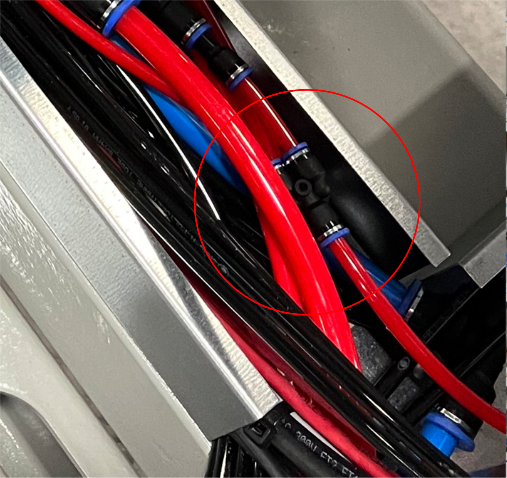
Étape 9 - 12mm red connection Z support pilot 1
Add 12mm Y connector at point A
Add 12mm to 8mm reducer, then 8mm to 6mm reducer , then connect 6mm red pipe to exit through grommit and feed pilot valve on z support cylinder 1
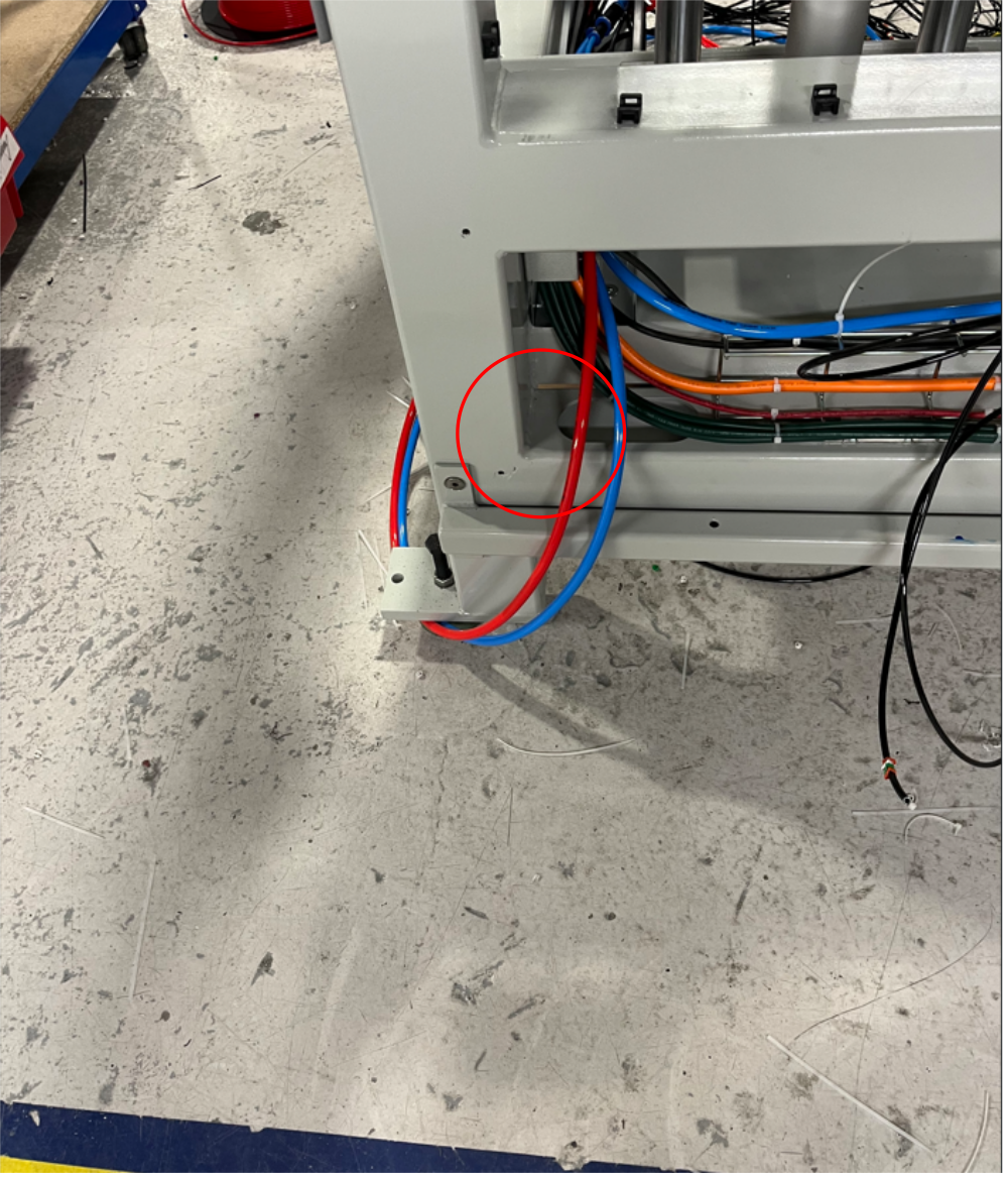
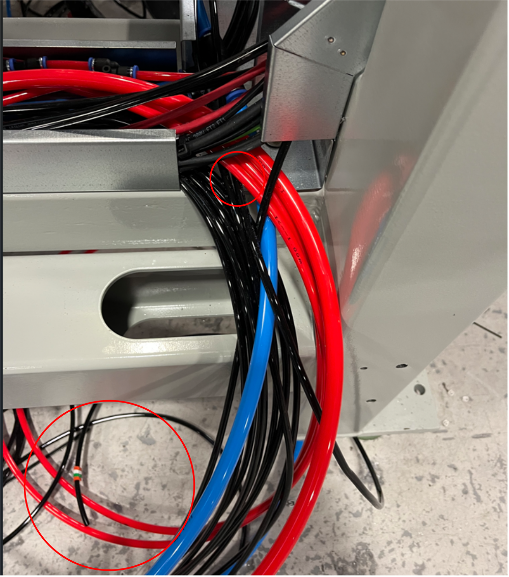
Étape 10 - 12mm red connection rear lower panel
Connect previous fitted 12mm Y connector to rear 12mm bulkhead fitting
run pipe along wire basket at rear
Étape 11 - 12mm red connection 12mm from bulkhead
Connect 12mm red pipe front front 12mm bulkhead to Y connector at indicated point
fit 12mm to 8mm reducer then 8mm to 6mm reducer and connect 6mm red pipe to feed pilot valve on z support cylinder 2
Étape 12 - 12mm red connection rear bulkhead
Connect previous fitted Y connector to rear bulkhead with 12mm pipe
Étape 13 - Z support cylinder Feeds
Connect 6mm red pipe to Out port on Z support cylinder
Add 6mm Y connector and connect 2 off 6mm red airpipes to route into trunking and feed both Z support check valves
Étape 14 - VZ support cylinder feed
Connect 8mm red pipe to OUT port on VZ support regulator and feed base QEV valve on VZ support cylinder
Étape 15 - Z support exhaust
Add 6mm black airpipes to QEV on z support cylinders
Run through trunking to exit point indicated
Connect to blowers on swarf chute
Draft
 Français
 English
 Deutsch
 Español
 Italiano
 Português