Pneumatic installation details for ZX5 module B

Difficulté
Difficile
Durée
8 heure(s)
Sommaire
- 1 Introduction
- 2 Étape 1 - Unless otherwise stated
- 3 Étape 2 - Machine Handing
- 4 Étape 3 - Y269 Ring blow output
- 5 Étape 4 - Y270 Clamp hold
- 6 Étape 5 - Y350 Clamp infeed top
- 7 Étape 6 - Y351 infeed side clamp
- 8 Étape 7 - Y360 work blowers
- 9 Étape 8 - Y386 Outfeed clamps
- 10 Étape 9 - Y389 V cut
- 11 Étape 10 - Y395 Clamps V
- 12 Étape 11 - 12mm blue connections Ring feed
- 13 Étape 12 - 12mm blue connections Valve bank supply
- 14 Étape 13 - 12mm blue connection V cut valve
- 15 Étape 14 - Rear pipe exit handing
- 16 Étape 15 - Finalise ring main
- 17 Étape 16 - 12mm red Connection Bulkhead /Air gun
- 18 Étape 17 - 12mm Red connection Z support cylinder
- 19 Étape 18 - 12mm red connection VZ support cylinder
- 20 Étape 19 - 12mm red connection Z support pilot 1
- 21 Étape 20 - 12mm red connection rear lower panel
- 22 Étape 21 - 12mm red connection 12mm from bulkhead
- 23 Étape 22 - 12mm red connection rear bulkhead
- 24 Étape 23 - Z support cylinder Feeds
- 25 Étape 24 - VZ support cylinder feed
- 26 Étape 25 - Z support exhaust
- 27 Commentaires
Introduction
Tools Required
Pipe cutters
Pipe identification numbers
Parts Required
D0015703 Air Gun Bracket x 1
P0000010 Elbow Adaptor 6mm - 1/8 BSPT (Taper thread) x 2
P0000046 Fitting: 'Y' Adaptor 6mm x 4
P0000053 6mm T (P16) x 2
P0000075 Parallel Y Connector 8mm x 1
P0000077 Straight Adaptor 8mm - 1/8BSP x 3
P0000160 Fitting: Flow Controller In Line 6mm x 4
P0000161 Plug-in Reducer 6mm Tube 8mm Fitting x 6
P0000401 6mm inline non return valve x 2
P0000470 Valve: 5/2 PnPnu 1/8BSP x 1
P0000513 Ball valve with QS connector x 1
P0000551 6mm inline Quick Exhaust Fitting x 6
P0001106 Plug in reducer 12mm to 8mm x 7
P0001107 12mm Y connector x 8
R0015114 Bench Assemble Valve banks and Regulators
Étape 1 - Unless otherwise stated
Use Loctite 243 on all fasteners
Use Loctite 572 on all threaded pneumatic connection
Pen mark all fasteners to show finalised

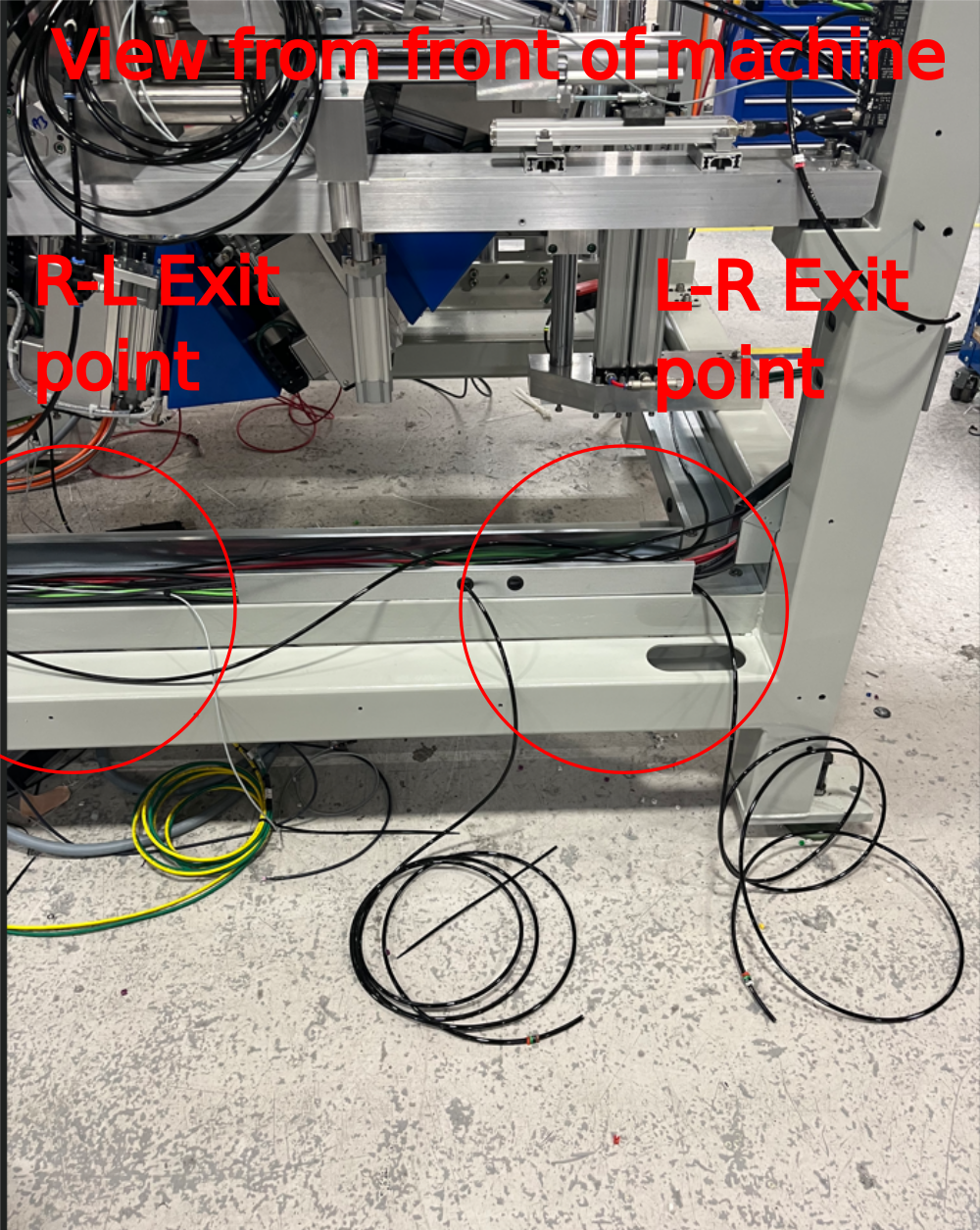
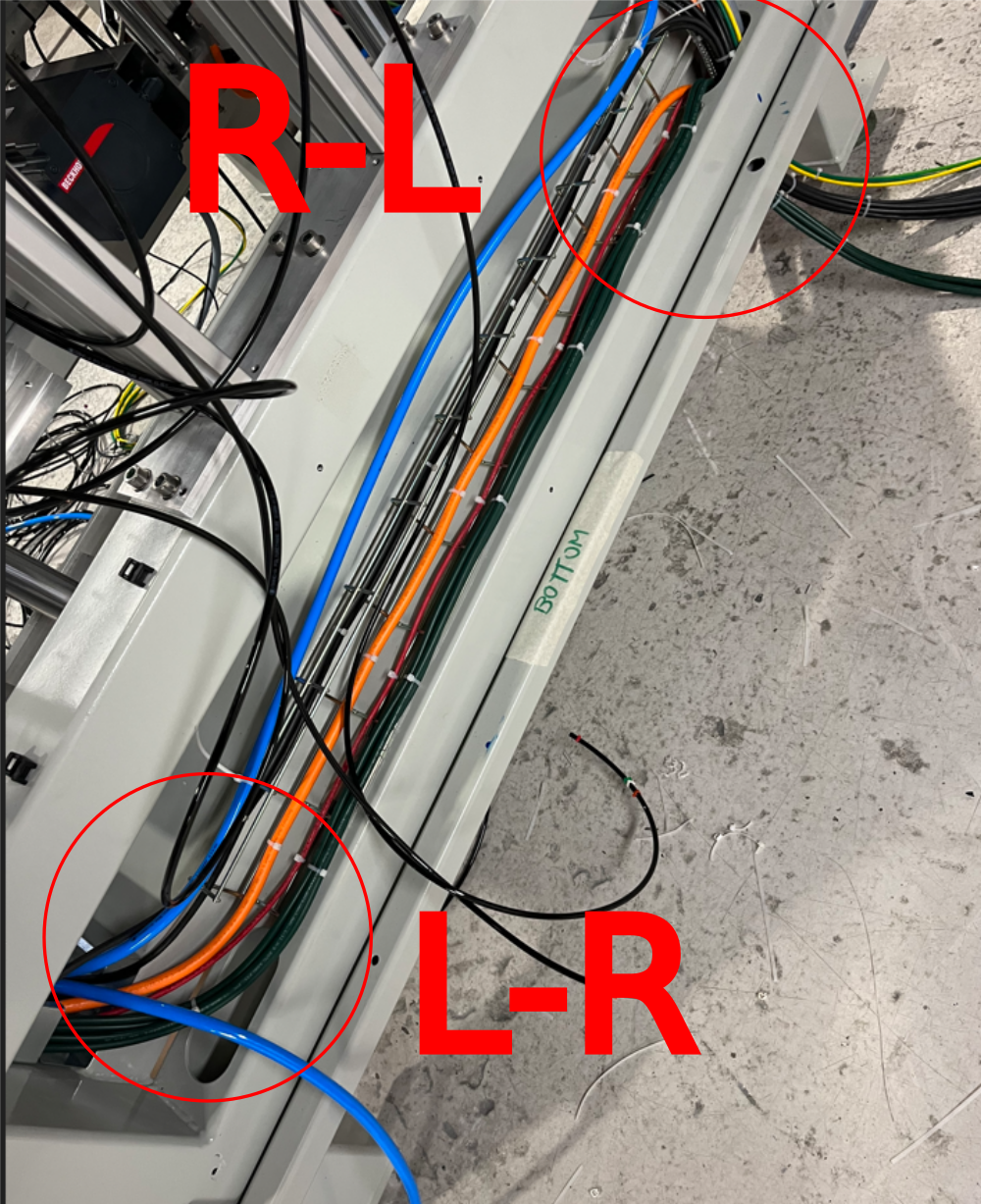
Étape 2 - Machine Handing
Exit point of shown pipes changes in respect to hand of machine
Photo shows L-R configuration
For R-L configuration, the pipes must exit the trunking on the left side ( opposite to shown picture)
Étape 3 - Y269 Ring blow output
Pipe id 2699
Pipe trailing from rotary head energy chain
Route into trunking and exit as shown to valve bank
Blank port 2


Étape 4 - Y270 Clamp hold
Pipe id 2701
Connect to port 2 on valve bank
Through trunking as shown
Connect to Nose of clamp hold cylinder
Pipe id 2709
Connect to port 4 on valve bank
Through trunking as shown
Leave 2 meter tails on both pipes exiting the trunking
Handing. Pipes always exit trunking as shown next to side clamp assembly


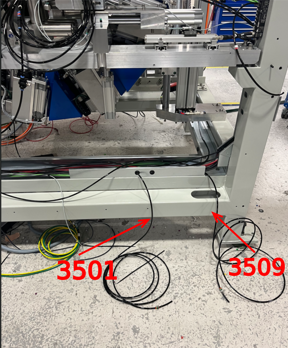
Étape 5 - Y350 Clamp infeed top
Pipe id 3501
Connect to port 2 on valvebank
Through trunking and exit at point shown
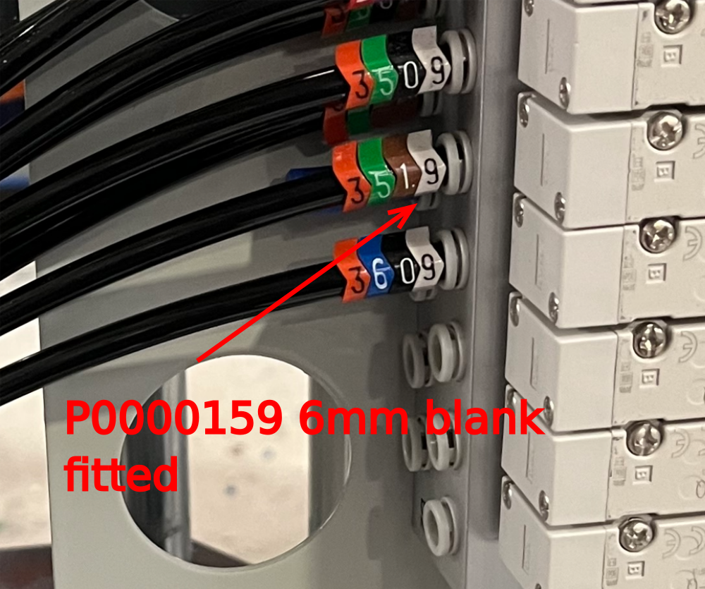
Pipe id 3509
Connect to port 4 of valvebank
Through trunking and exit at point shown
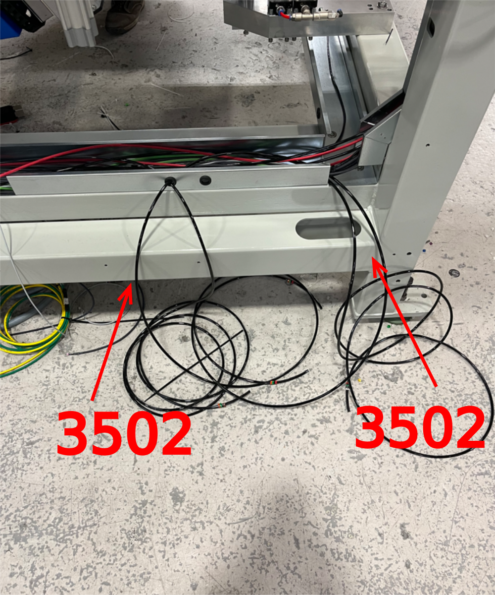
Pipe ID 3502
Run pipe between points shown

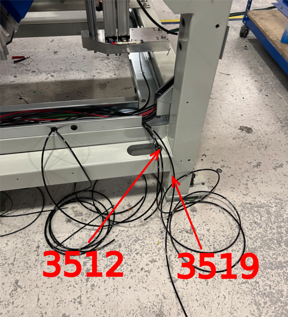
Étape 6 - Y351 infeed side clamp
Pipe ID 3511
Connect to port 2 on valve bank
Through trunking and exit at point shown
Pipe ID 3519
Connect to port 4 on valvebank
Through trunking and exit as shown
Pipe ID 3512
Through trunking and exit as shown
leave pipes coiled up ready for later connection


Étape 7 - Y360 work blowers
Pipe Id 3609
Connect to port 4 on valvebank
Blank port 2
Route through trunking and exit as shown.
Leave 1.5meters of pipe from trunking exit
Handing, pipe will always exit trunking at side shown opposite to side clamp connections


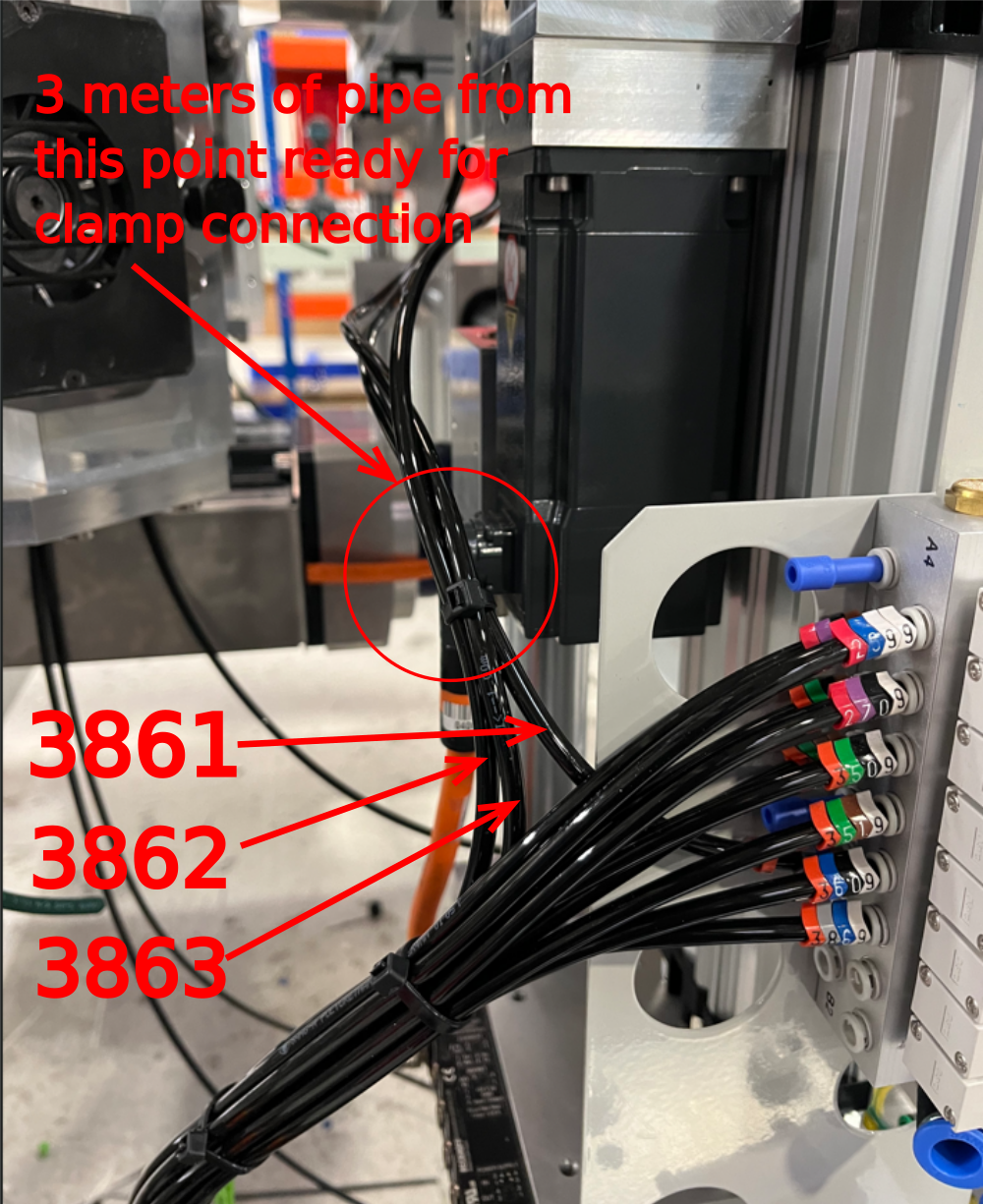
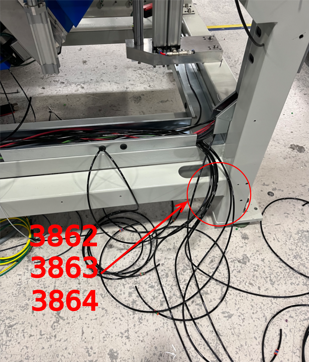
Étape 8 - Y386 Outfeed clamps
Pipe 3861
From port 2 of valvebank directly up to clamp area shown
3862 routes from clamp area to point shown out of trunking
3863 routes from clamp area to point shown out of trunking
3869 connects from port 4 on valve bank and routes to trunking exit point as shown

Étape 9 - Y389 V cut
Connect pipe 3891 to port 2 of valve bank and route as shown . Leave 1 meter tail exiting trunking
Connect pipe 3899 to port 4 of valve bank and route as shown . Leave 1 meter tail exiting trunking
Handing. Pipe exit will always be the trunking closet to the support cylinder with air adjustment fittings


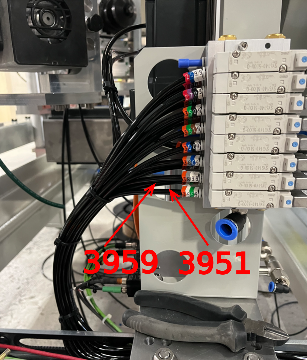
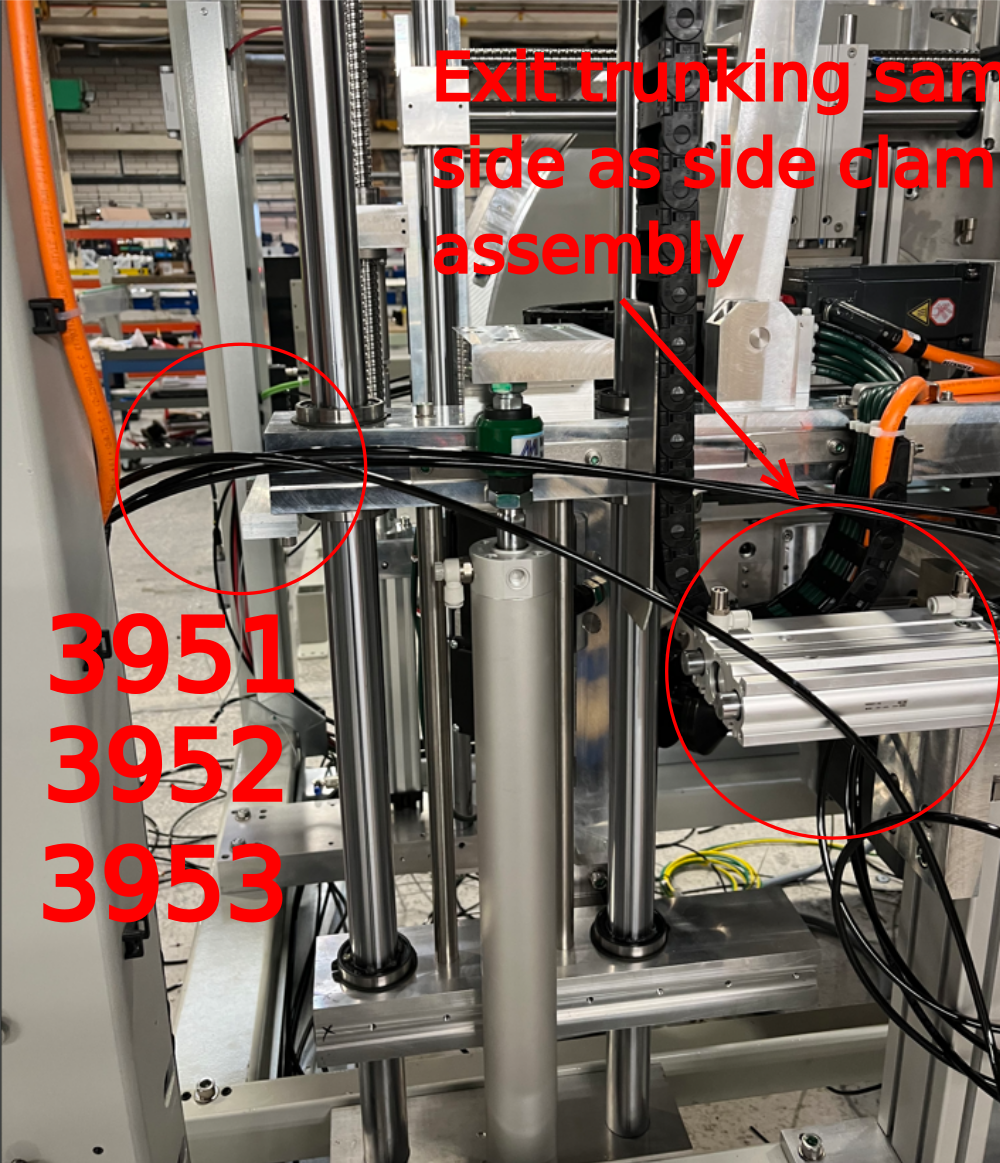
Étape 10 - Y395 Clamps V
3951
Connect to port 2 on valve bank then route through trunking and exit as shown
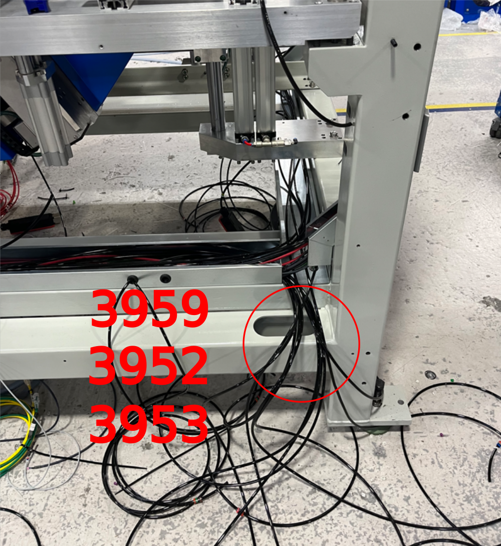
3959
Connect to port 4 on valve bank then route through trunking and exit as shown
3952
Route between points shown
3953
Route between points shown
Ensure 3 meters of pipe are left for connection once pipes exit trunking
Leave coiled ready for later connection


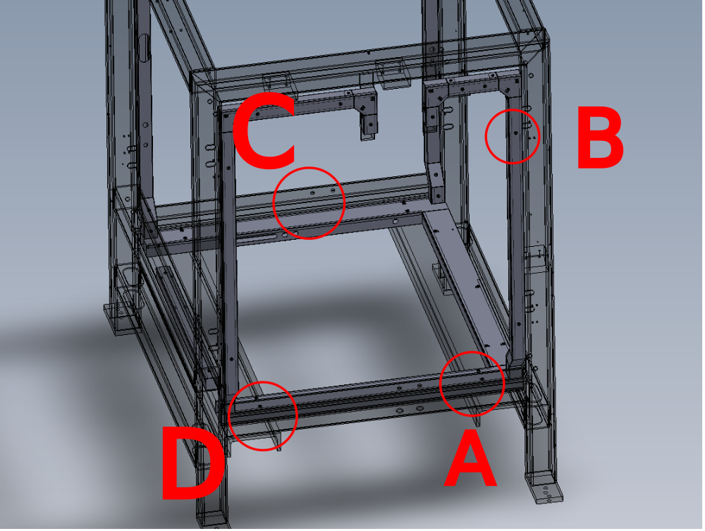
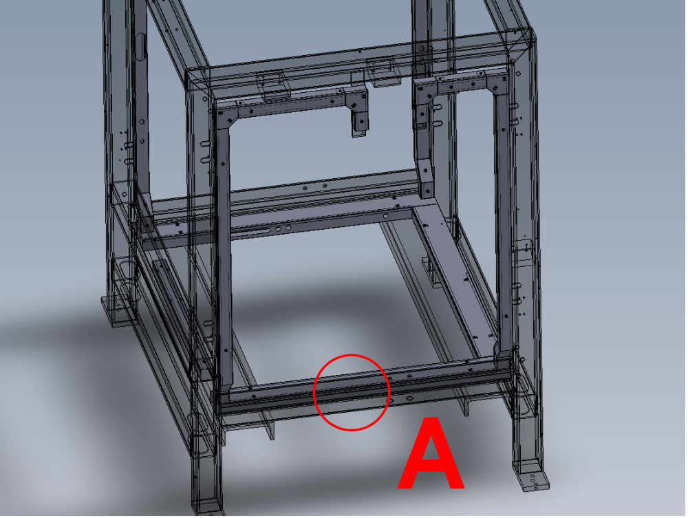
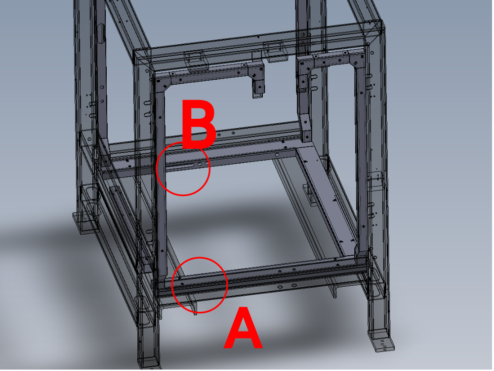
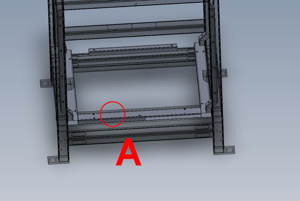
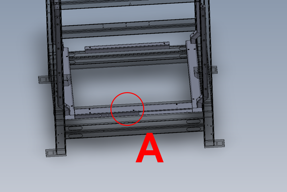
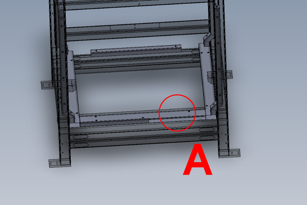
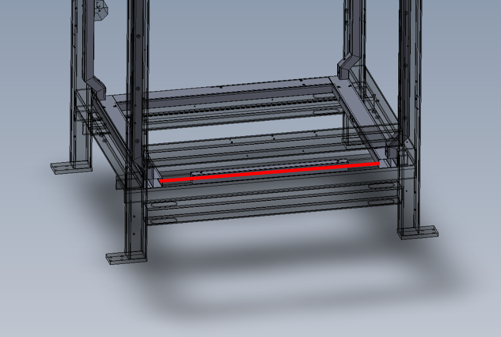
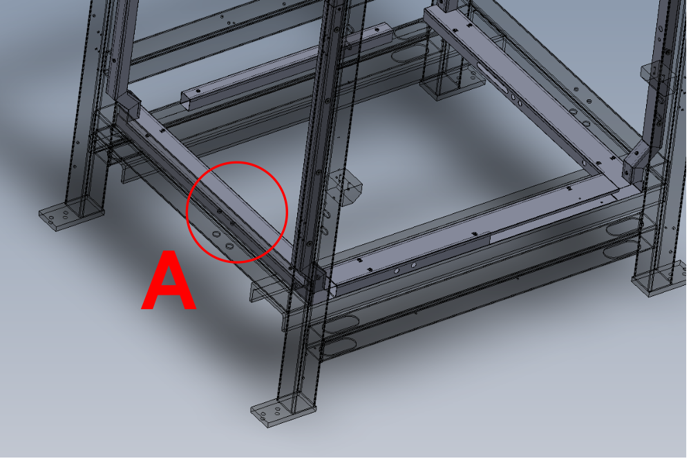
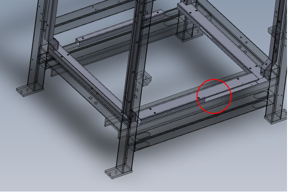
Étape 11 - 12mm blue connections Ring feed
Connection for 12mm ring main as follows
Retrieve 6mm blue pipe from point B, and route down trunking to point A
At point A, connect 6mm blue pipe to fittings as shown
Use
P0001107 12mm Y x 1
P0000161 8-6mm reducer x 1
P0001106 12-8mm reducer x 1
Route 2 off 12 mm blue pipes from fittings as shown to points C and D

Étape 12 - 12mm blue connections Valve bank supply
Add 12mm Y fitting as shown, and connect additional 12mm pipe and exit as shown to provide valve bank air supply
Use
P0001107 12mm


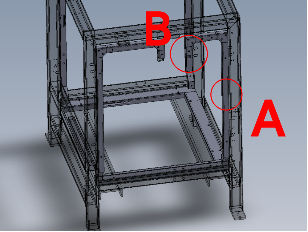
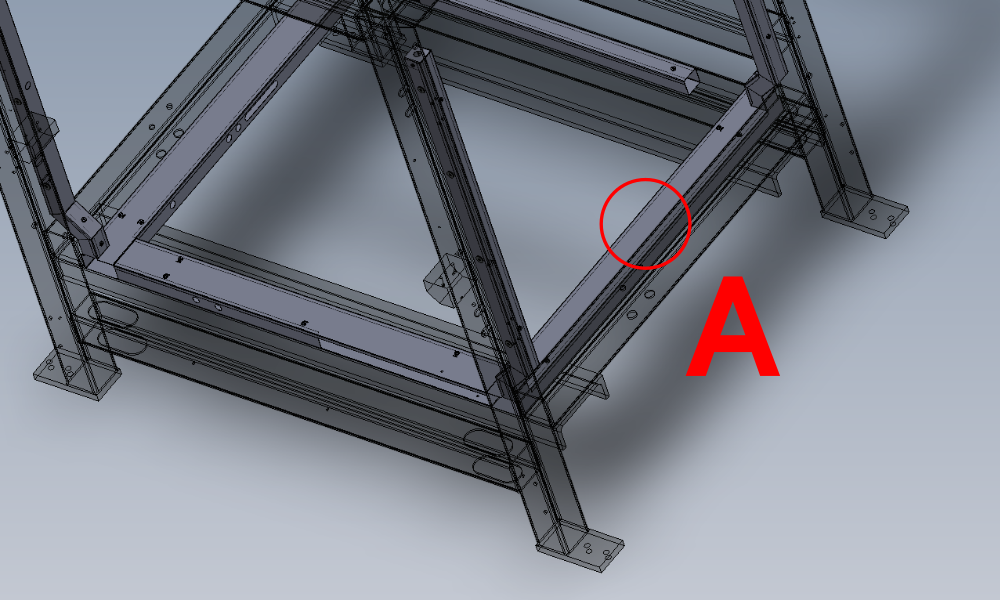
Étape 13 - 12mm blue connection V cut valve
Connect previous 12mm Y connector to new 12mm Y connector at point A or B
(please note this position will change depending on handing . Position will be determined by the location of the exit point for step 9 , Y389)
Use 12mm to 8mm reducer and connect 8mm blue air pipe , feed out of grommit along with previous fitted 2 off pipes 3891 and 3899
Use
P0001107 12mm y connector
P0001106 12-8mm reducer

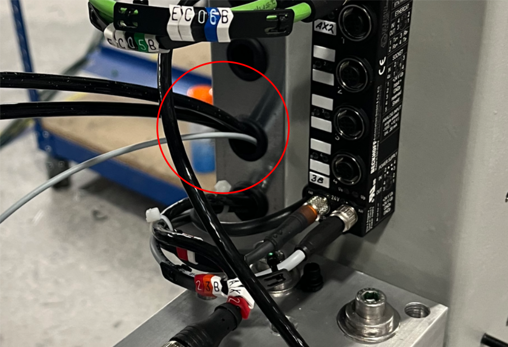
Étape 14 - Rear pipe exit handing
Rear pipe exits change depending on handing of machine
As viewed from rear
R-L pipes exit on the left
L-R pipes exit on the right (shown in picture)
Add 12mm y connector to split current 12mm blue pipe to provide supply pipe to exit rear of machine
Use
P0001107 12mm Y connector

Étape 15 - Finalise ring main
Bring both 12mm blue pipes to point shown ad use 12mm Tee connector to join.
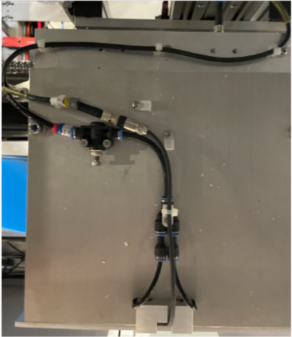
Étape 16 - 12mm red Connection Bulkhead /Air gun
Connect 1st 12mm bulkhead on lower front panel with 12mm red pipe
Add 12mm Y connector at point A and fit 12mm to 8mm reducer then add 8mm red pipe to exit trunking and feed Air gun regulator port IN
Étape 17 - 12mm Red connection Z support cylinder
Add new 12mm Y Connector at point A and connect to previous Y connector .
Add 12mm to 8mm reducer and 8mm to 6mm reducer to provide 6mm red pipe to feed to Z support cylinder regulator port IN
Add P0000501 non return to 6mm red pipe just before entry into In port
Étape 18 - 12mm red connection VZ support cylinder
Add 12mm Y connector at point indicated and connect to previous 12mm Y connector
Add 12mm to 8mm reducer and connect 8mm red pipe to feed VZ regulator port IN
Étape 19 - 12mm red connection Z support pilot 1
Add 12mm Y connector at point A
Add 12mm to 8mm reducer, then 8mm to 6mm reducer , then connect 6mm red pipe to exit through grommit and feed pilot valve on z support cylinder 1
Étape 20 - 12mm red connection rear lower panel
Connect previous fitted 12mm Y connector to rear 12mm bulkhead fitting
run pipe along wire basket at rear
Étape 21 - 12mm red connection 12mm from bulkhead
Connect 12mm red pipe front front 12mm bulkhead to Y connector at indicated point
fit 12mm to 8mm reducer then 8mm to 6mm reducer and connect 6mm red pipe to feed pilot valve on z support cylinder 2
Étape 22 - 12mm red connection rear bulkhead
Connect previous fitted Y connector to rear bulkhead with 12mm pipe

Étape 23 - Z support cylinder Feeds
Connect 6mm red pipe to Out port on Z support cylinder
Add 6mm Y connector and connect 2 off 6mm red airpipes to route into trunking and feed both Z support check valves

Étape 24 - VZ support cylinder feed
Connect 8mm red pipe to OUT port on VZ support regulator and feed base QEV valve on VZ support cylinder
Étape 25 - Z support exhaust
Add 6mm black airpipes to QEV on z support cylinders
Run through trunking to exit point indicated
Connect to blowers on swarf chute
Draft
 Français
 English
 Deutsch
 Español
 Italiano
 Português