Assembly instructions for installation of main rotary drive ring

Difficulté
Difficile
Durée
3 heure(s)
Sommaire
- 1 Introduction
- 2 Étape 1 - Quality Check Drive ring D0006423-2mod
- 3 Étape 2 - Check For holes (ECR)
- 4 Étape 3 - Prepare Faceplate For assembly
- 5 Étape 4 - Inspect Journal washers D0006503
- 6 Étape 5 - Inspect Journals
- 7 Étape 6 - Check drive ring wipers
- 8 Étape 7 - Hepco Ring Quality check
- 9 Étape 8 - Position face plate
- 10 Étape 9 - Mount Journals
- 11 Étape 10 - Adjust Eccentric Journals to widest Position and position ring
- 12 Étape 11 - WARNING
- 13 Étape 12 - First stage journal positioning
- 14 Étape 13 - Mount D.T.I and set position 1,3 and 4
- 15 Étape 14 - Adjust position 5 and 6
- 16 Étape 15 - Finalise Journal tension
- 17 Étape 16 - Quality Check
- 18 Étape 17 - Fit lubricators
- 19 Étape 18 - Clean and inspect rotary ring cover
- 20 Étape 19 - Mount Rotary ring cover to main assembly
- 21 Étape 20 - Add Ring fixings
- 22 Étape 21 - Add thread locking
- 23 Étape 22 - Add thread locking
- 24 Commentaires
Introduction
Detailed steps to correctly install rotary gear and journals
Checks for correct installation of oil feed system
Tolerance limits and requirements
Tools Required
Standard hex key set
0-25mm micrometer
Ring support blocks for assembly
Work Table
Mag Base and D.T.I
Hepco flat spanner
17mm socket
Torque Wrench
Parts required
D0006423-2mod Drive ring x 1
D0007651 Face plate x 1
B0000185 journal x 6
B0000186journal x 2
D0006503 Journal washer x 8
D00007692 wiper x 4
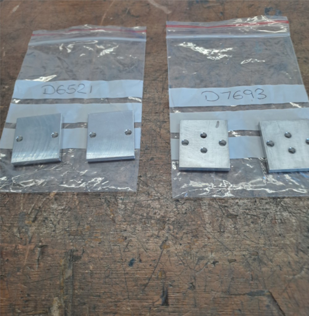
D0006521 x2
D0007693 x 2
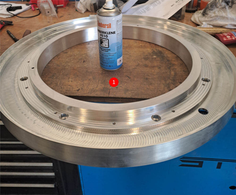
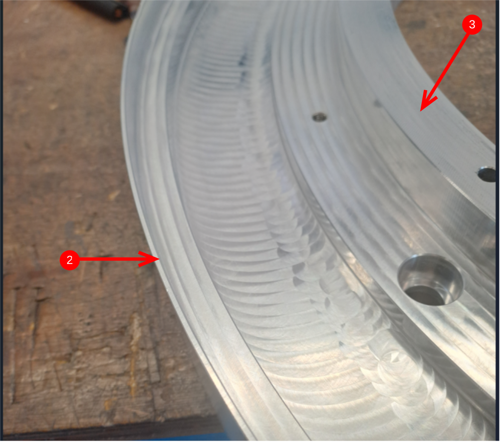
D0007713 rotary ring cap x 1Étape 1 - Quality Check Drive ring D0006423-2mod
Rotary drive ring needs checking before fitment.
- Check teeth for burrs, damage and debris. Use compressed air to clean all areas
- V edge should be checked for damage. Check entire circumference with fingers to identify any damage, lumps or high low spots
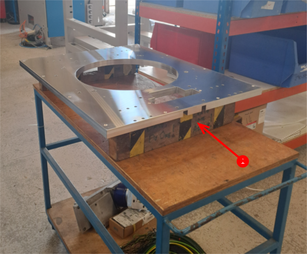
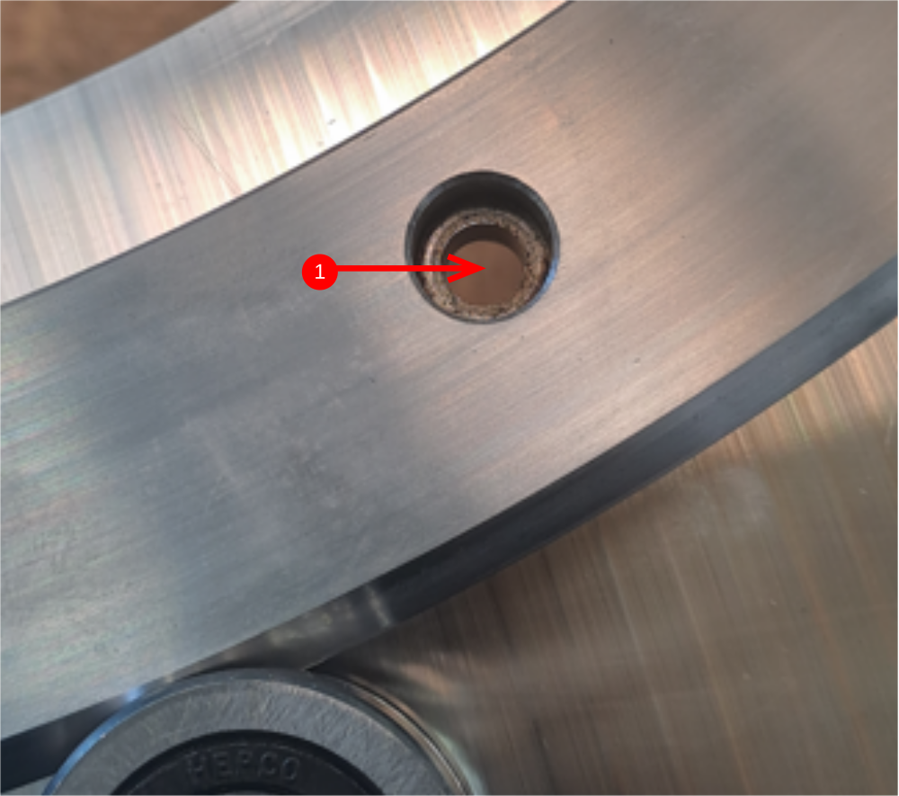
- Check drive ring has been countersunk in the shown area

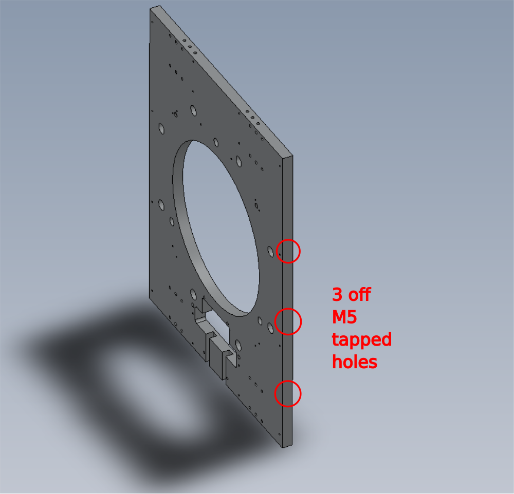
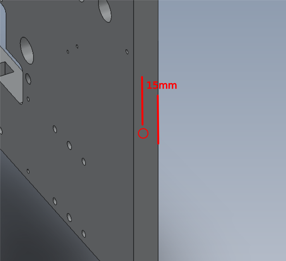
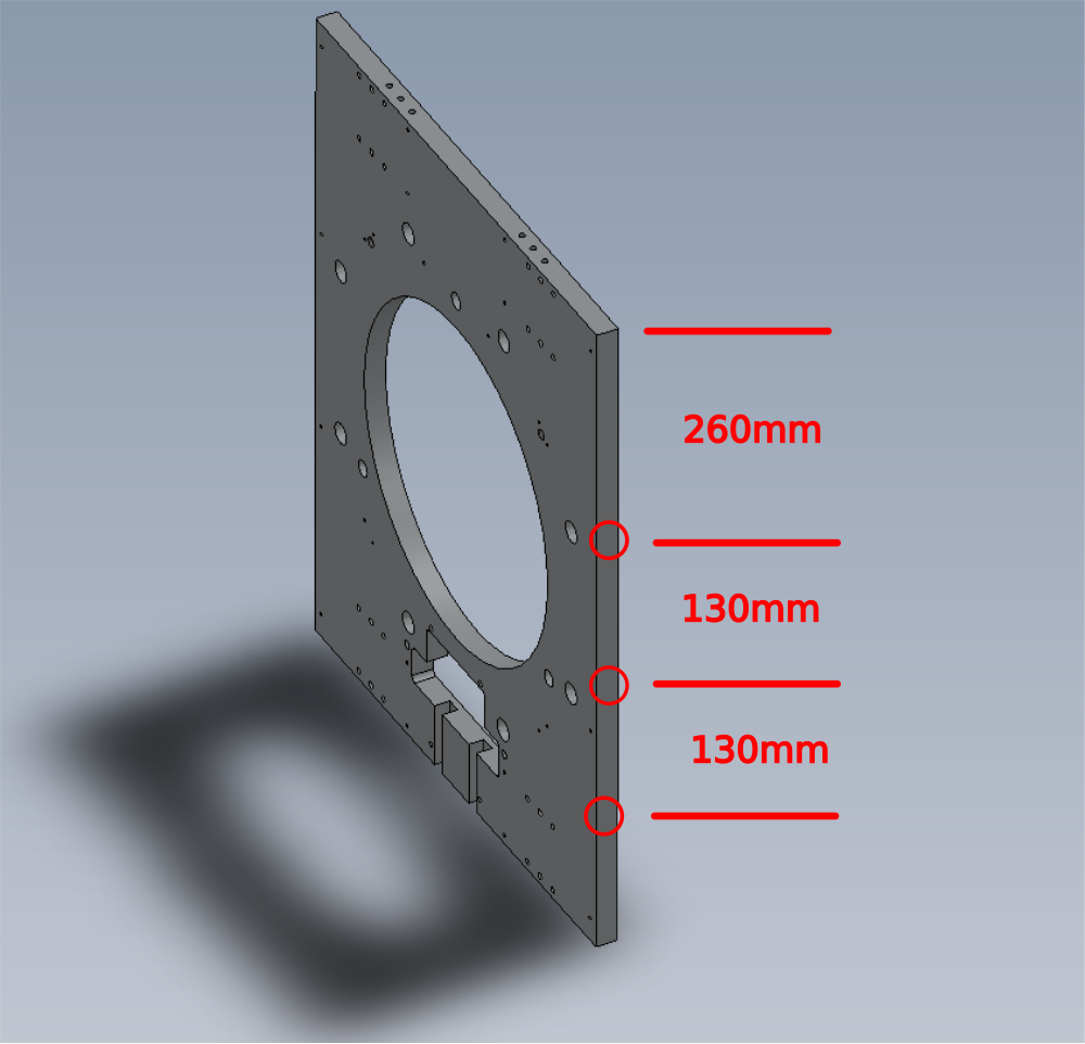
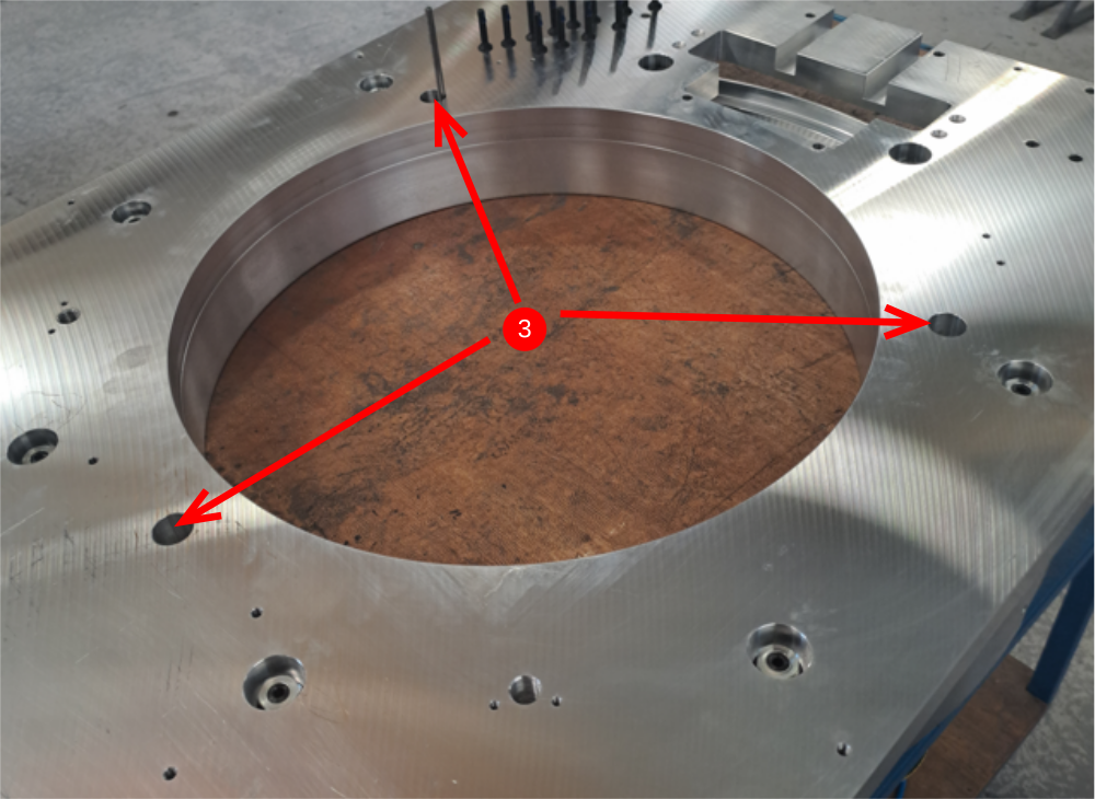
Étape 2 - Check For holes (ECR)
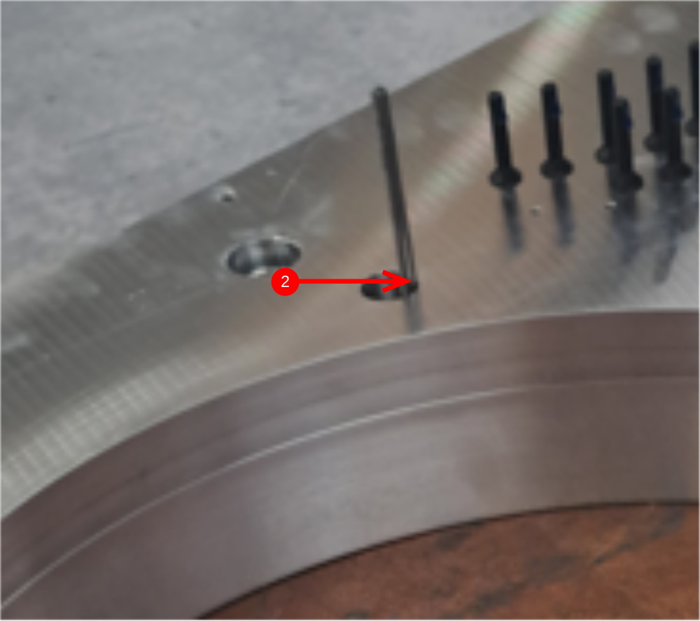
Check faceplate has pre drilled 3 off M5 tapped holes on indicated face .
Drill by hand if not present to dimensions shown before assembly commences
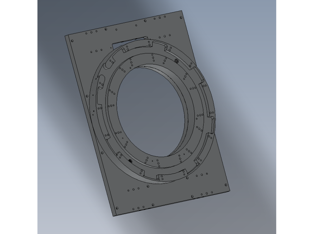
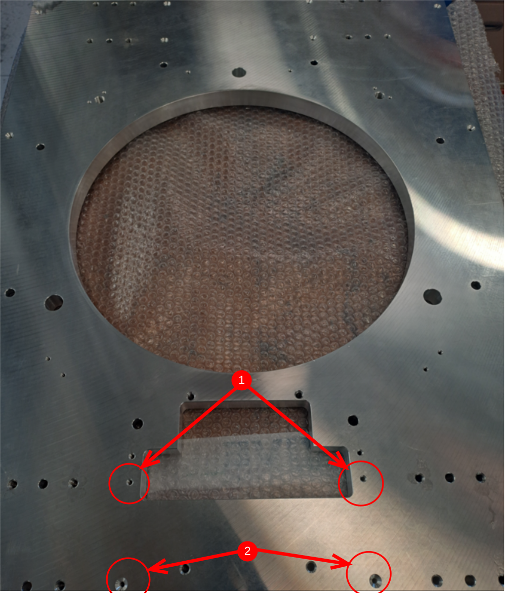
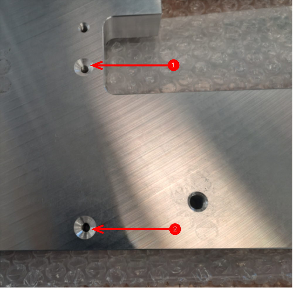
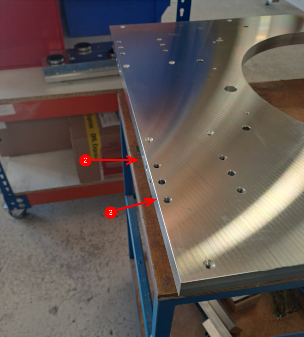
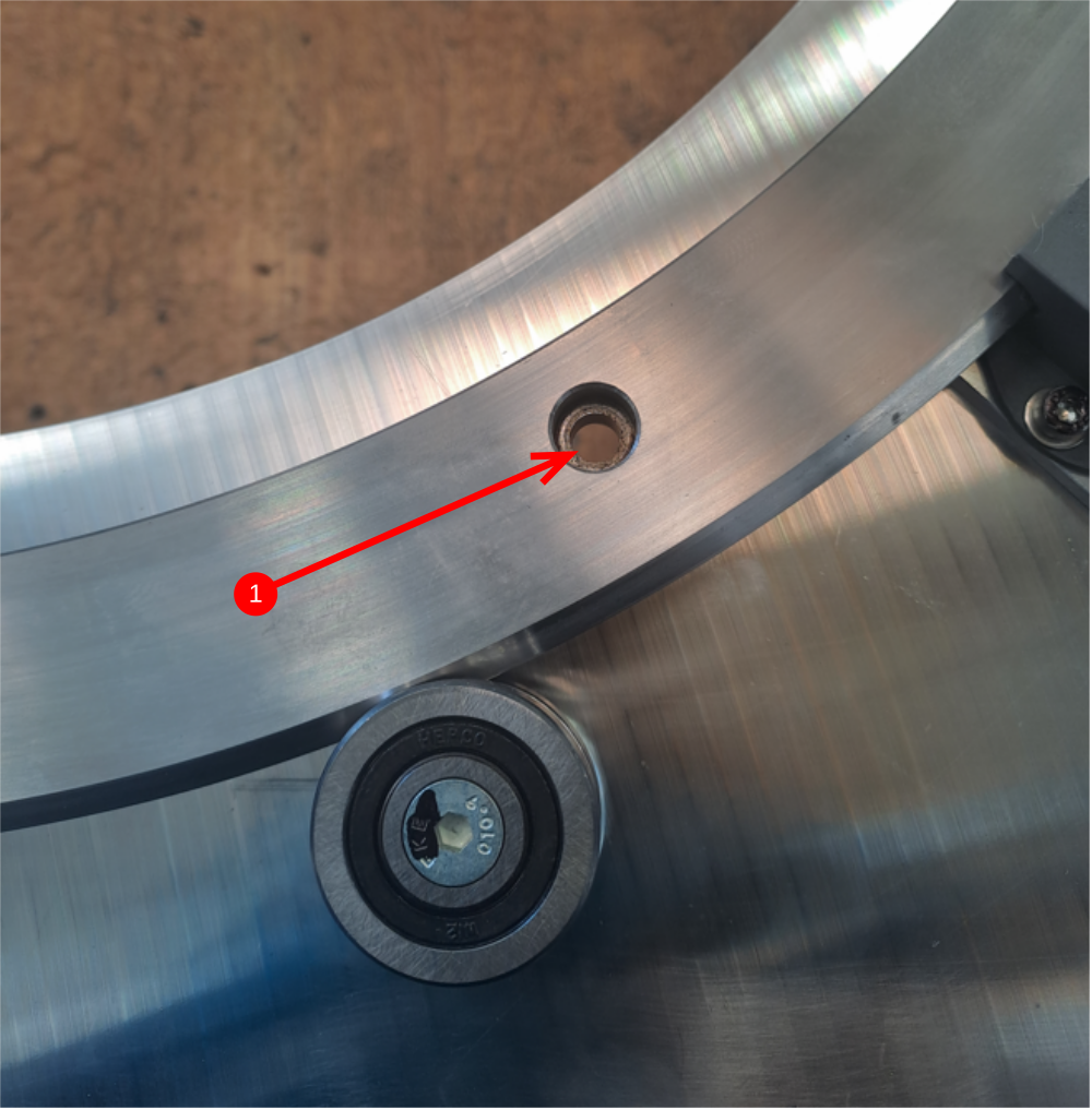
Étape 3 - Prepare Faceplate For assembly
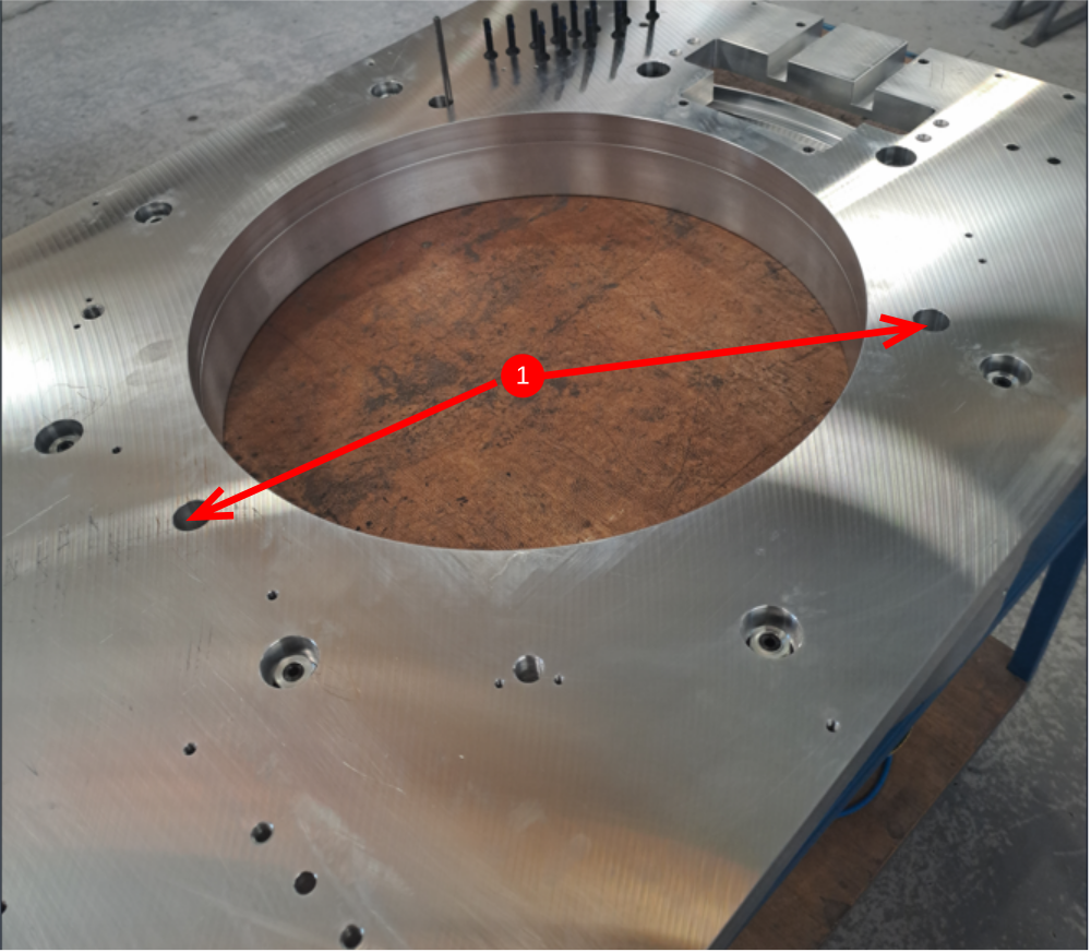
Check that D0007651faceplate holes indicated (1) are countersunk the same as holes indicated (2 ). If not , countersink to correct
3. Clean all holes with compressed air
Thoroughly clean faceplate with solvent

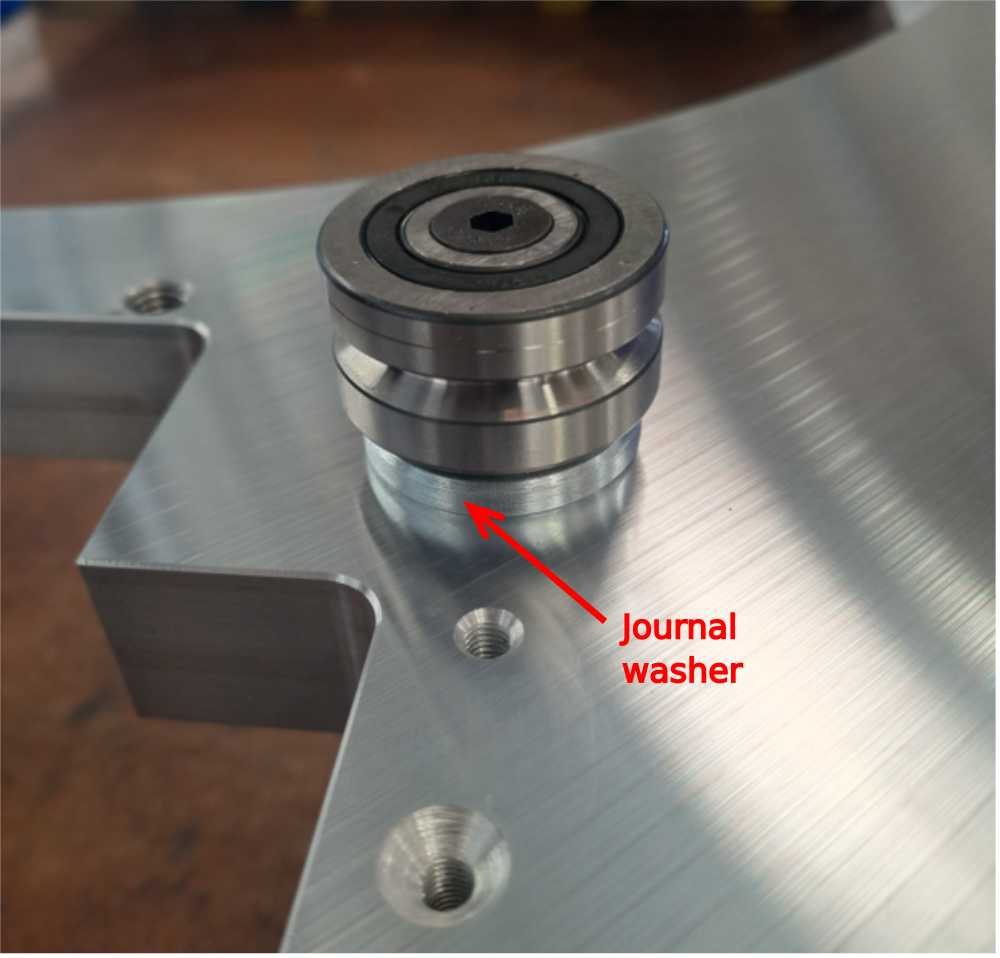
Étape 4 - Inspect Journal washers D0006503
Journal washers should be inspected to ensure all washers supplied are within tolerance .
Thickness of washer should not exceed 0.05mm difference between all washers supplied. Report any that are incorrect via NCR system


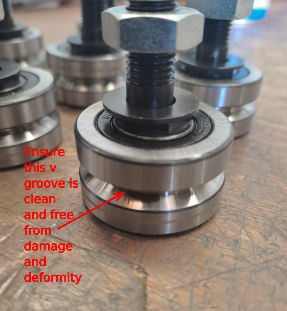
Étape 5 - Inspect Journals
B0000185 and B0000186 journals should be cleaned with compressed air and checked for quality. Visually inspect v grooves of journals for and damage or irregularities

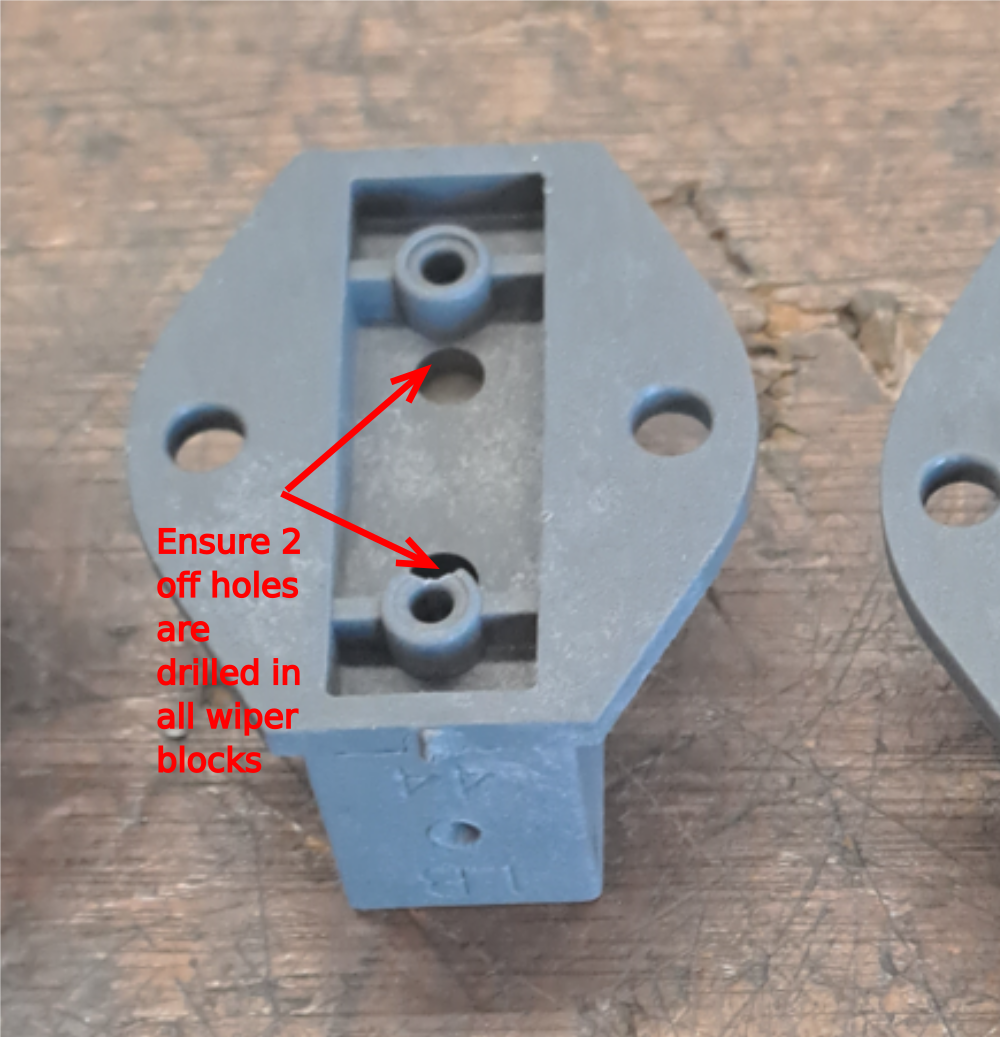
Étape 6 - Check drive ring wipers
D0007692 should be checked for correct machining. Holes indicated are vital to allow oil flow to ring system once assembled.

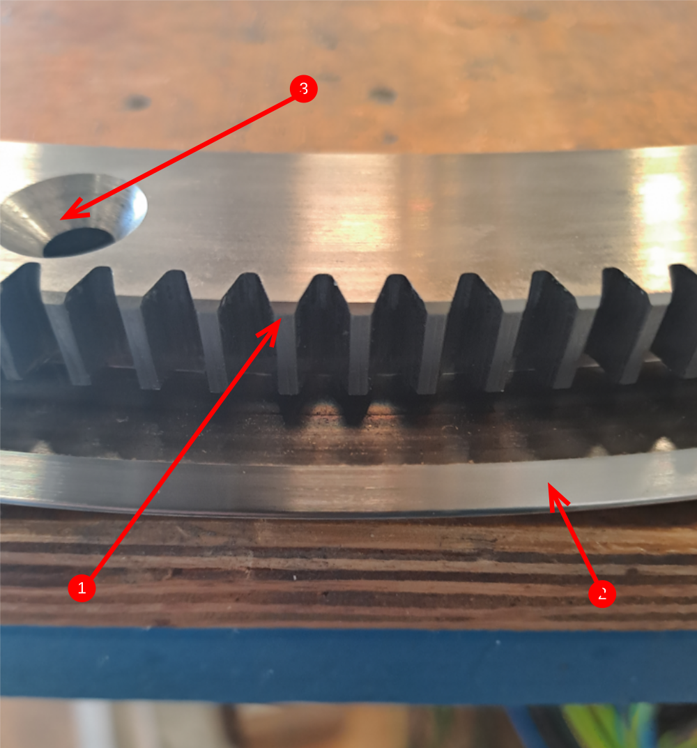
Étape 7 - Hepco Ring Quality check
It is vital to check that the correct ring has been issued to production
To check, measure pitching of teeth as shown.
Correct ring will have tooth pitching of 7mm


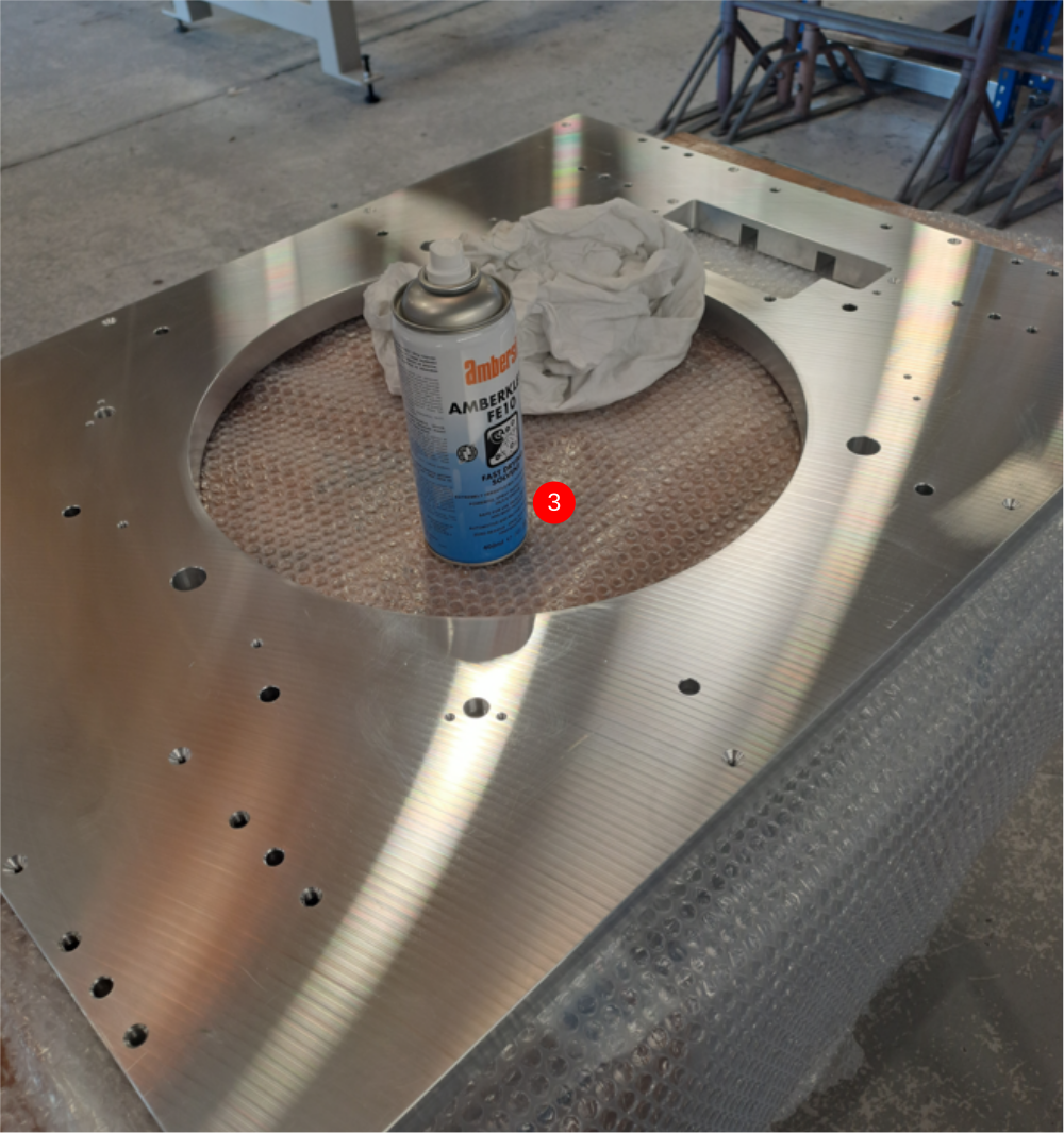
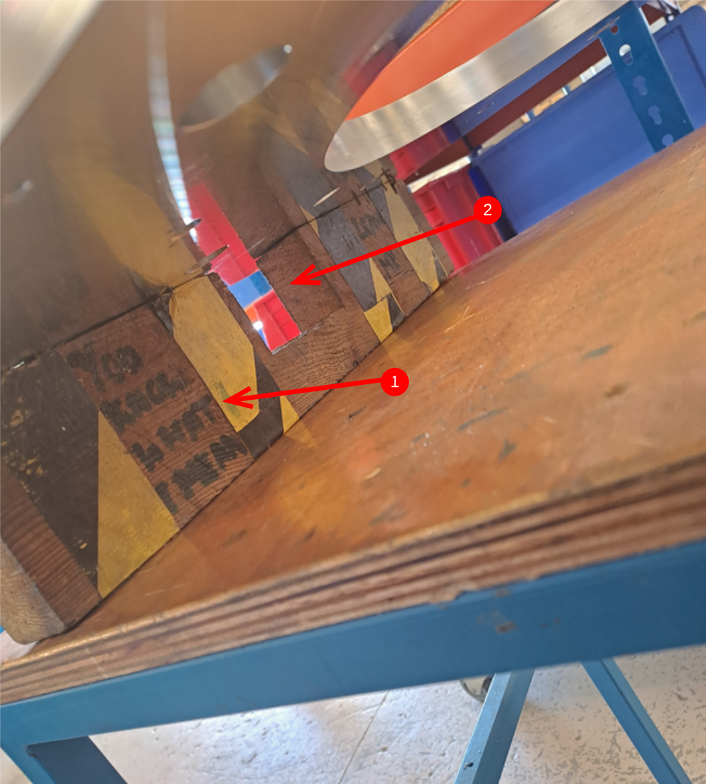
Étape 8 - Position face plate
Face plate should be positioned ready for assembly
1 Support blocks should be placed either end of faceplate
2 Ensure cut out is orientated correctly as per picture. This is the lifting access point.
3 Ensure correct end of faceplate is located at edge of workstation (end with 6 off M8 tapped holes on indicated face)
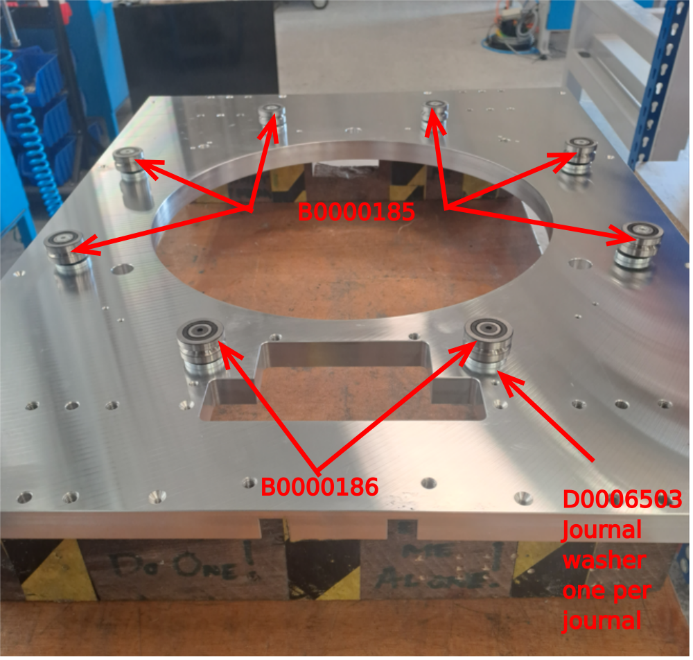
Étape 9 - Mount Journals
Mount journals as shown
Eccentric B0000185 journal 6 off
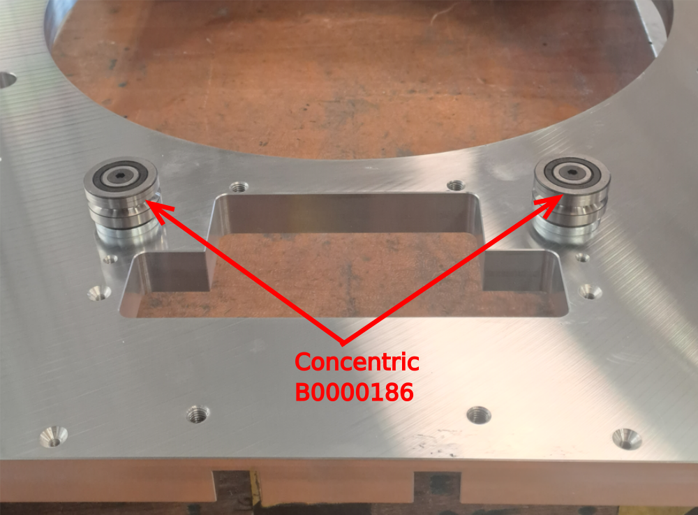
Concentric B0000186 journal 2 off
Space each journal with D0006503 journal washer
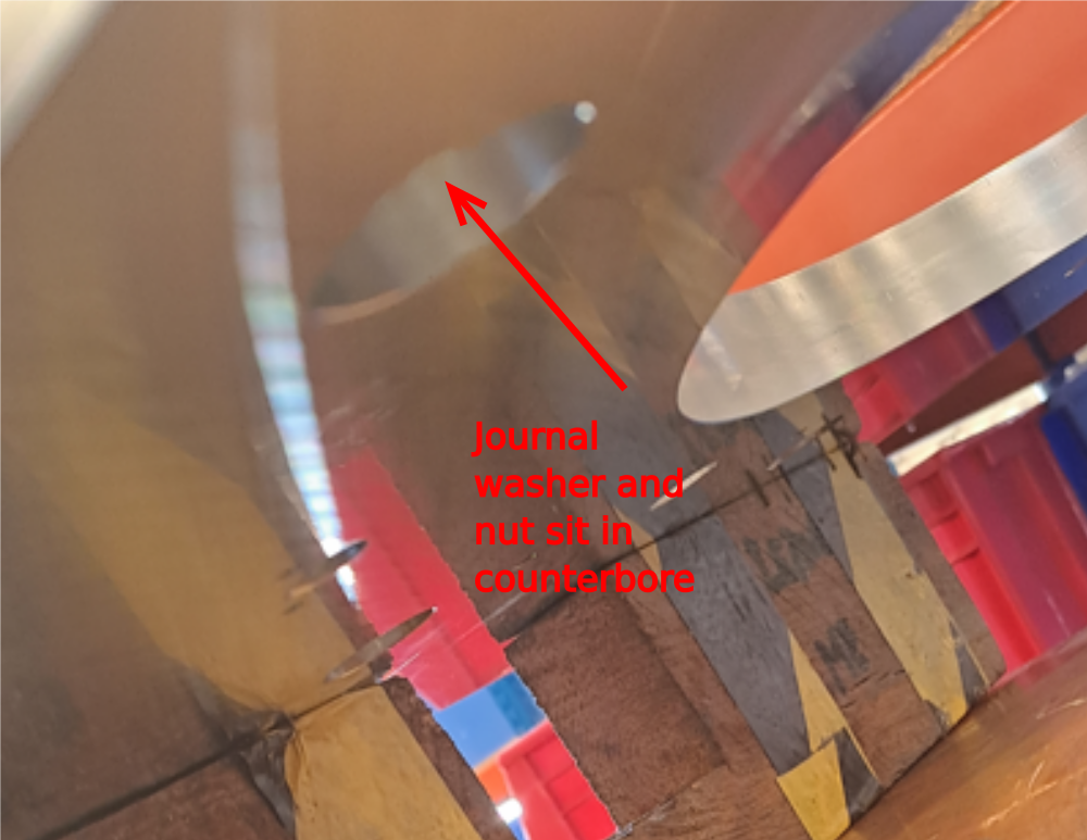
Fit Journal washer and nut to opposite side of mounted journal .
Add light tension to nut, as adjustment will be required
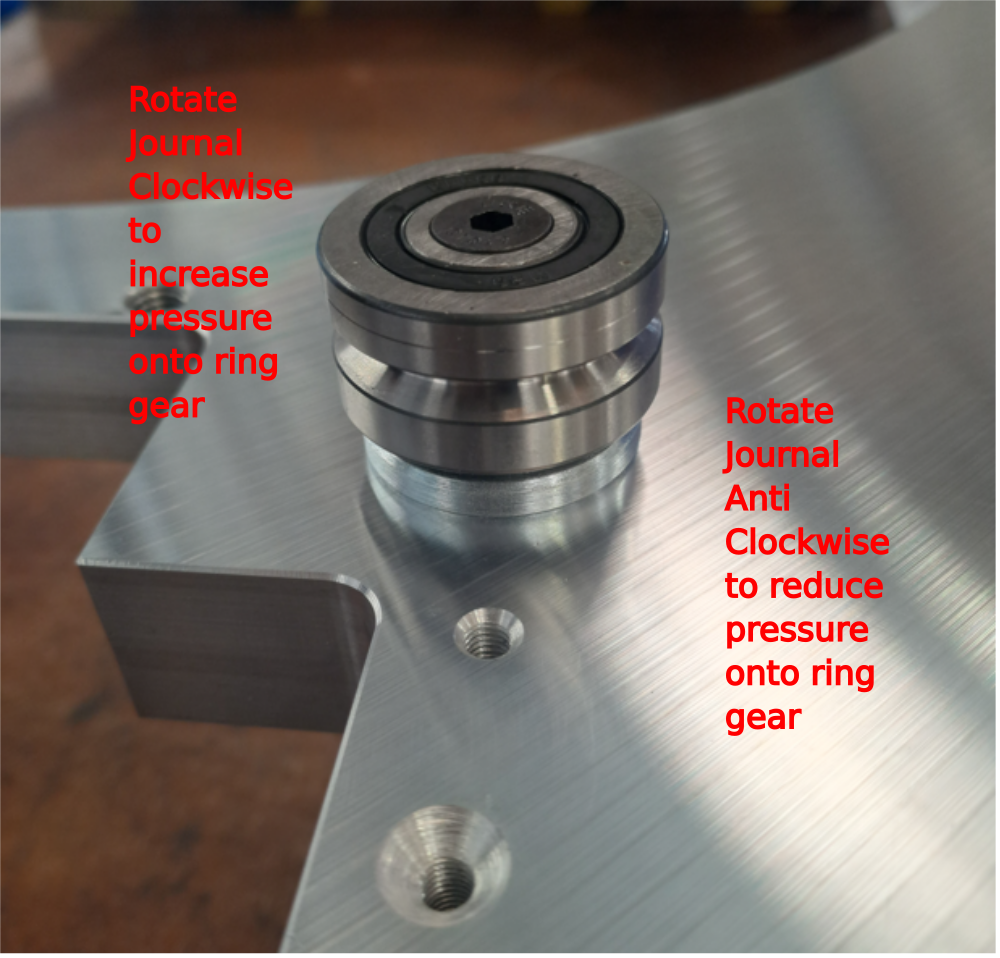
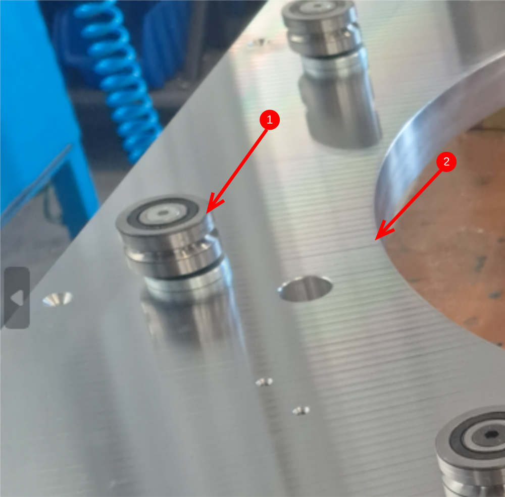
Étape 10 - Adjust Eccentric Journals to widest Position and position ring
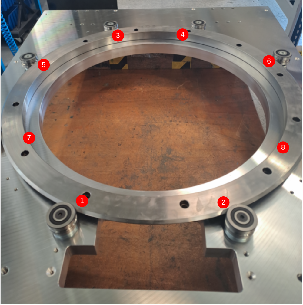
Adjust eccentric journals to their widest point to allow ring gear to be fitted . See point 1 and 2 , these two points need to be as far apart as possible by rotating the eccentric journal with the flat hepco adjustment spanner .
Place hepco drive gear as shown inside journals


Étape 11 - WARNING
It is very easy to deform the journals and hepco ring with to much tension being applied to the journals. It is vital this doesn't happen as it can render parts useless for application.
Tension should be applied in small increments, and a D.T.I should be used on tension setting to monitor journal movement when adjusting and tightening.

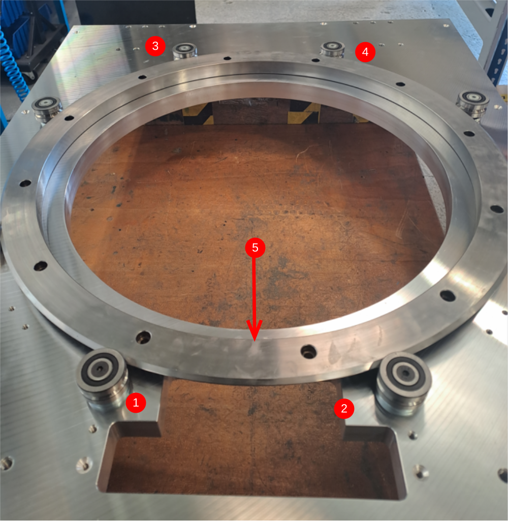
Étape 12 - First stage journal positioning
The set the initial position of the drive ring the following steps are required
- Pull by hand hepco ring at indicated point (5) towards journals 1 and 2
- Whilst held in this position adjust journals 3 and 4 to engage onto the drive ring
...Only apply enough pressure on journals 3 and 4 to captivate the ring in position and remove any movement from the Hepco ring and journal contact
Étape 13 - Mount D.T.I and set position 1,3 and 4
D.T.I and mag base and stand should be mounted to rotary ring as shown
- move the D.T.I to the position in front of a concentric journal (1) and zero D.T.I.
- move to position 3 and adjust journal to achieve slight contact. Use the D.T.I to gauge when contact occurs when adjusting. Stop when slight movement is visual on the D.T.I
- repeat at position 4
- Check that all journals can still be skidded when held whilst ring is rotated


Étape 14 - Adjust position 5 and 6
- Move to position 5 and adjust journal to achieve correct contact using the same method as the previous step
- Move to position 6 and repeat
- Repeat at positions 7 and 8
Now it is vital to check the following .
Rotate ring and check all journals can be skidded when held by hand
Return D.T.I to journal 1 and set to zero
Check reading now on all journals . Slowly adjust eccentric journals to bring D.T.I to +- 0.05mm
Ensure attention is paid to tension applied to journals, to ensure overtightening does not occur. Journals should always be able to be 'just' Skidded when held with firm hand pressure
Repeat these steps until all journals are adjusted to main rotary ring and all can be 'just' skidded when held tight on ring rotation.
Maximum tolerance for eccentricity is 0.05mm , so if journals have to be adjusted out of this tolerance, contact supervisor
Étape 15 - Finalise Journal tension
Now the rotary ring is mounted and concentric , journal nuts need to be torqued to the correct tension .
It is vital that the D.T.I is used to gauge if a journal moves when the nut is torqued to the correct setting .
Use the following sequence to set correctly
- Use flat hepco spanner to help stop rotation of journal when tightening
- Ensure D.T.I is in front of journal being tightened to indicate if movement occurs
- Use Torque wrench set to 33nm and tension journal nut.
- If the D.T.I indicates movement, it is vital the movement is corrected as this will affect journal contact and concentricity .
- Only move to the next journal when the worked on journal is 100% set and tight
- Mark each journal as tensioned when complete


Étape 16 - Quality Check
After tensioning is complete, recheck concentricity with D.T.I and also check journal tension.
Ring rotation should be smooth but with resistance
No high spots on rotation should be present.
Rotation should be quiet and even sounding
Supervisor check required at this point
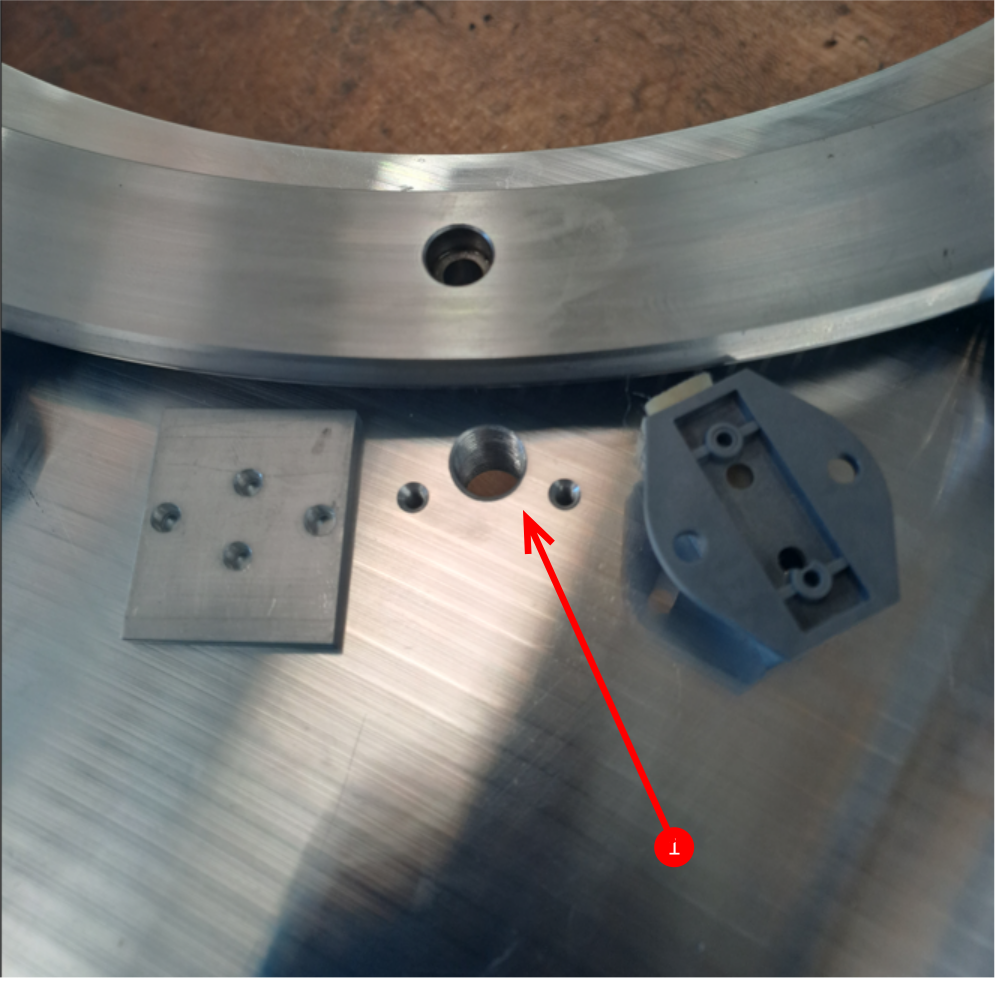
Étape 17 - Fit lubricators
D0006521 blank wiper spacer 2 off
D0007693 oil access spacer 2 off
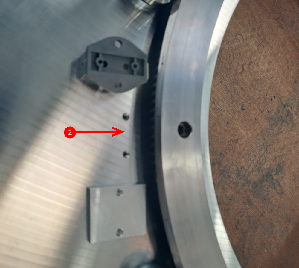
1 Fit D0007693 spacers with D0007692 wiper with m4 x 16 cap heads and M4 a form washers to area shown in picture with 1/4 bsp oil hole
2 Fit D0006521 blank wiper spacer with D0007692 wiper with m4 x 16 cap heads to area shown


Étape 18 - Clean and inspect rotary ring cover
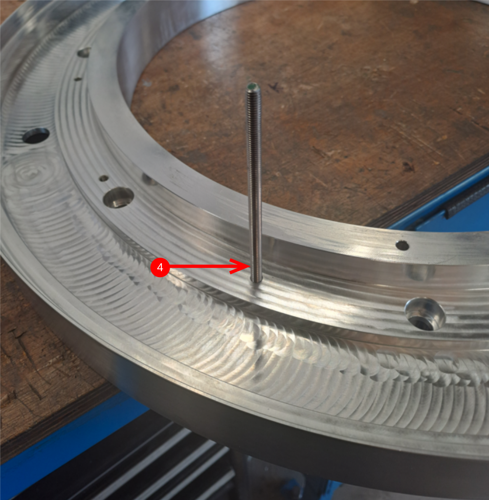
D0007713 rotary ring inspection
1 Thoroughly clean with Fe10 solvent and then compressed air
2 Check indicated face for damage
3 Check indicated face for signs of damage
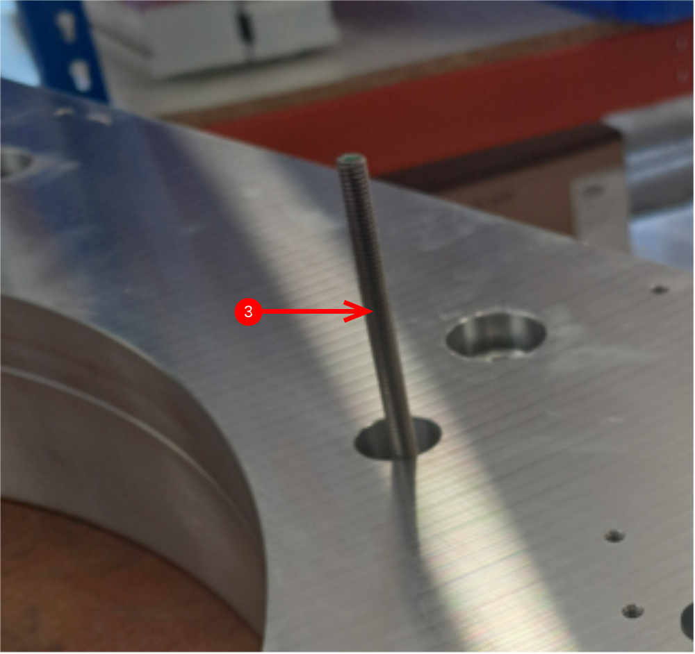
4 Add 1 off m6 x 120 studding (cut from stock) to indicated hole.
Note... Any of the m6 holes on this face can be used
Étape 19 - Mount Rotary ring cover to main assembly
1 Rotate hepco rotary ring until indicated holes align to allow the m6 stud to pass through hepco ring and face plate below
2 Fit rotary ring cover to main assembly using m6 studding to align as placed on top
3 Rotate assembly so stud is pointing up as shown
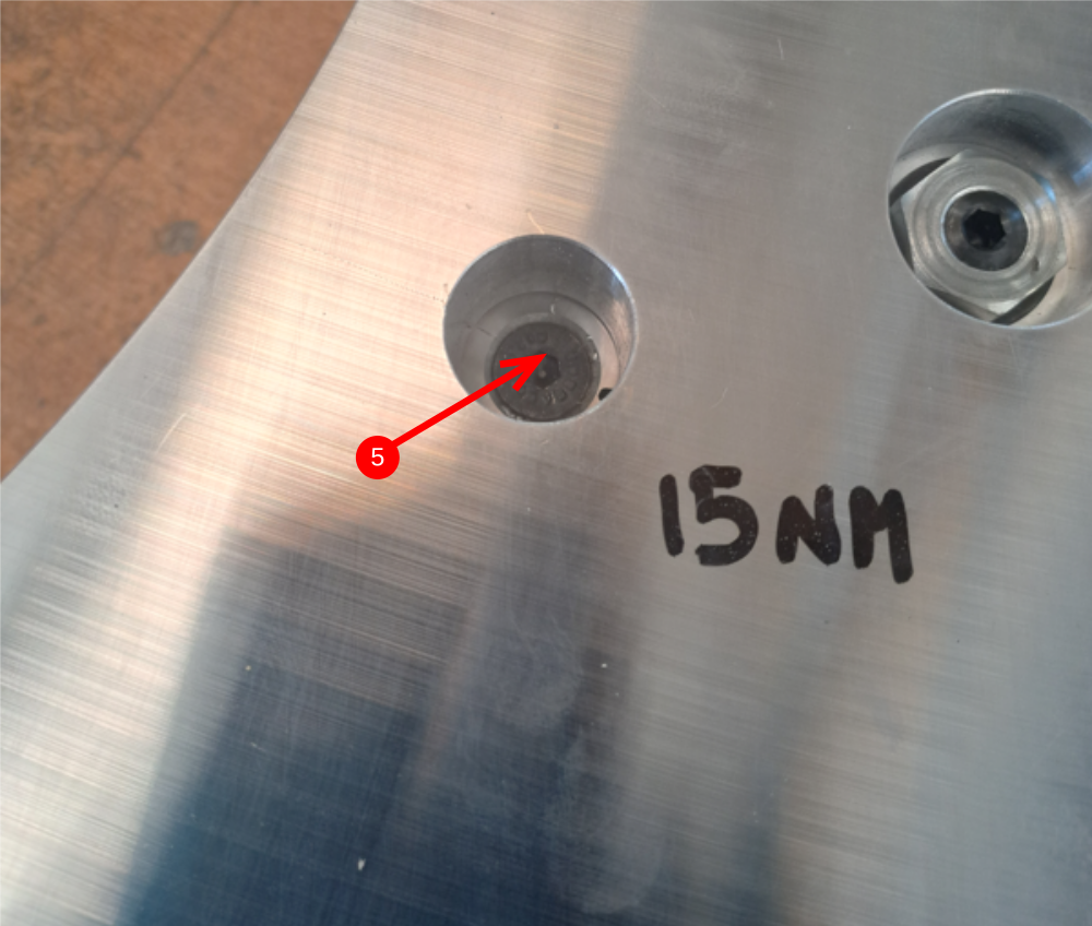
Étape 20 - Add Ring fixings
1 Add 2 off m6 counter sink bolts with loctite 243 to the indicated holes and lightly tension
2 Remove m6 studding and fit m6 countersink
3 Rotate ring 45 degrees to expose next set of 3 holes in inspection holes
Fit 3 more m6 countersink bolts
4 Rotate and repeat again until all 12 bolts are fitted and lightly tensioned.
5 Use a torque wrench to finalise bolts to 15nm .Methodically tighten each set of 3 bolts , rotating 45 degrees each time until all 12 bolts have been fully tensioned
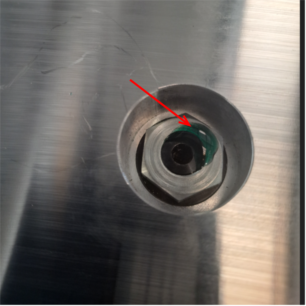
Étape 21 - Add thread locking
Loctite 290 Self wicking thread lock is used to lock journal nuts in place
Add one drop to each journal as indicated
Allow ring assembly to sit for 1 hour minimum to allow loctite to flow around threads before rotating assembly for next build sequence

Étape 22 - Add thread locking
Loctite 290 Self wicking thread lock is used to lock journal nuts in place
Add one drop to each journal as indicated
Allow ring assembly to sit for 1 hour minimum to allow loctite to flow around threads before rotating assembly for next build sequence
Draft
 Français
 English
 Deutsch
 Español
 Italiano
 Português