Correct build checks for assembly of R0000706 datum rollers

Difficulté
Moyen
Durée
1 heure(s)
Sommaire
- 1 Introduction
- 2 Étape 1 - Unless otherwise stated
- 3 Étape 2 - Check fit of shafts in bearings
- 4 Étape 3 - Degrease and bearing fit
- 5 Étape 4 - Add circlip and fit roller
- 6 Étape 5 - Mount rollers
- 7 Étape 6 - Assemble Blower rails
- 8 Étape 7 - Mount blower rails
- 9 Étape 8 - Fit pipe work
- 10 Commentaires
Introduction
Tools required
External circlip pliers
Standard hex key set
Pipe cutters
Pneumatic identification numbers
Parts Required
B0000062 Circlip 20mm External x 6
D0001176 Washer : bearing shim x 3
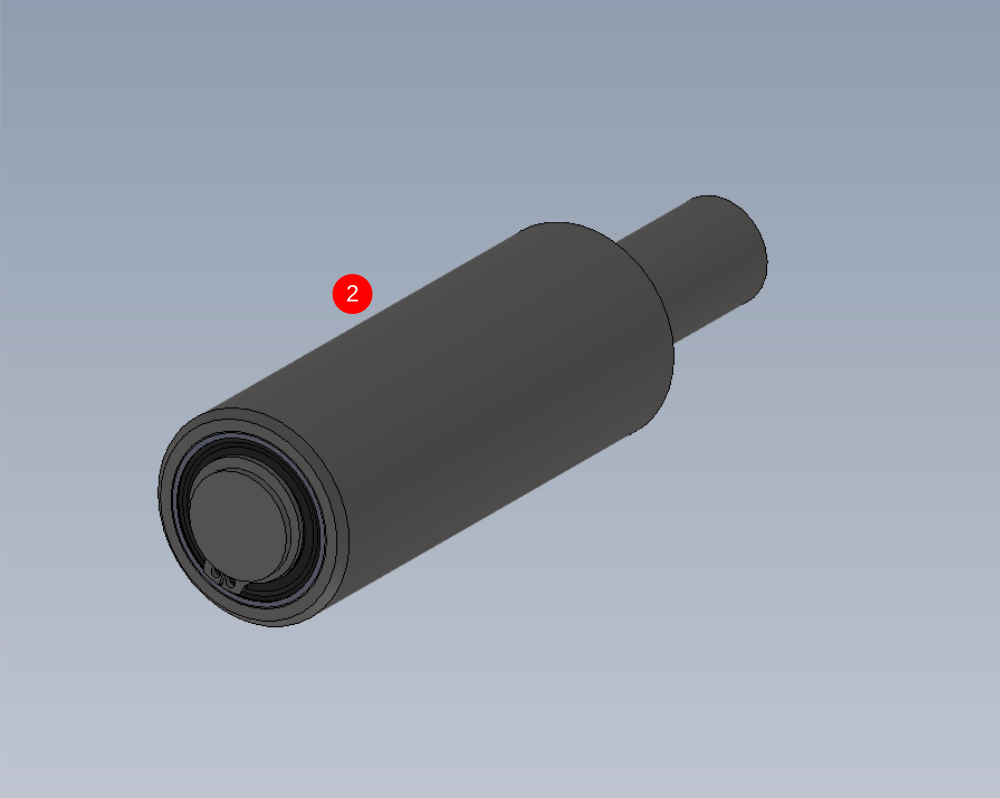
D0001333 Roller Ø40 x 80 c/w bearing x 3
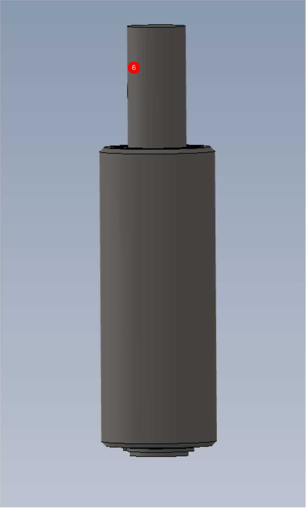
D0001334 Roller Ø40 x 102 c/w bearing x 3
D0003108 Shaft 20mm: 146mm Clamp Roller Shaft x 3
D0007677 Infeed Base Rail (D2972) x 1
D0007942 Shaft 20mm: 119.4mm ZX Datum Roller Circlip x 3
D0010896 Infeed Clamp Blower Vert x 1
D0010897 Infeed Clamp Blower x 1
P0000053 6mm T (P16) x 1
P0000160 Fitting: Flow Controller In Line 6mm x 1Étape 1 - Unless otherwise stated
Use locktite 243 on all fasteners
Use loctite 572 on all threaded pneumatic connection
Pen mark all fasteners to show finalised

Étape 2 - Check fit of shafts in bearings
Check fit of following parts .
Shafts should pass through bearings with only slight resistance . All inner bearing faces should have contact to shaft and rotate when the shaft is turned
Proceed to step 4 if fit is correct
If shafts are tight check drawing and inspect size of shaft .
If shaft slides through easily, then follow step 3
D0001333 Roller Ø40 x 80 c/w bearing x 3
D0001334 Roller Ø40 x 102 c/w bearing x 3
D0003108 Shaft 20mm: 146mm Clamp Roller Shaft x 3
D0007942 Shaft 20mm: 119.4mm ZX Datum Roller Circlip x 3

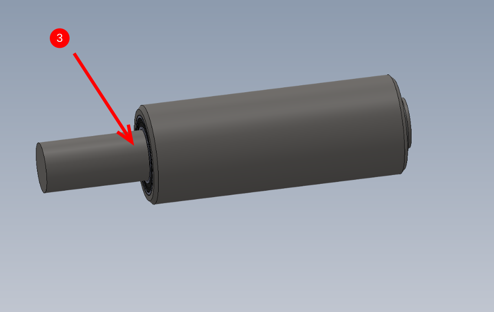
Étape 3 - Degrease and bearing fit
Thoroughly degrease all parts with FE10 solvent
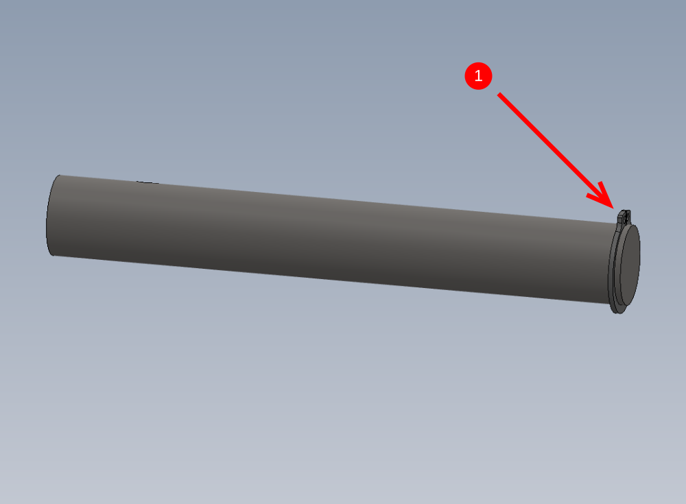
1 Fit 20mm external circlip to shaft
2 Fit roller to shaft
3 Add 3 drops of Loctite 641 bearing retainer to indicated area and smear around the shaft
4 Move shaft to shown position and add 3 more drops of bearing fit to indicated face and smear around
5 Position roller against circlip and remove any excess bearing fit with rag
6 Leave roller in a vertical position to allow bearing fit to cure
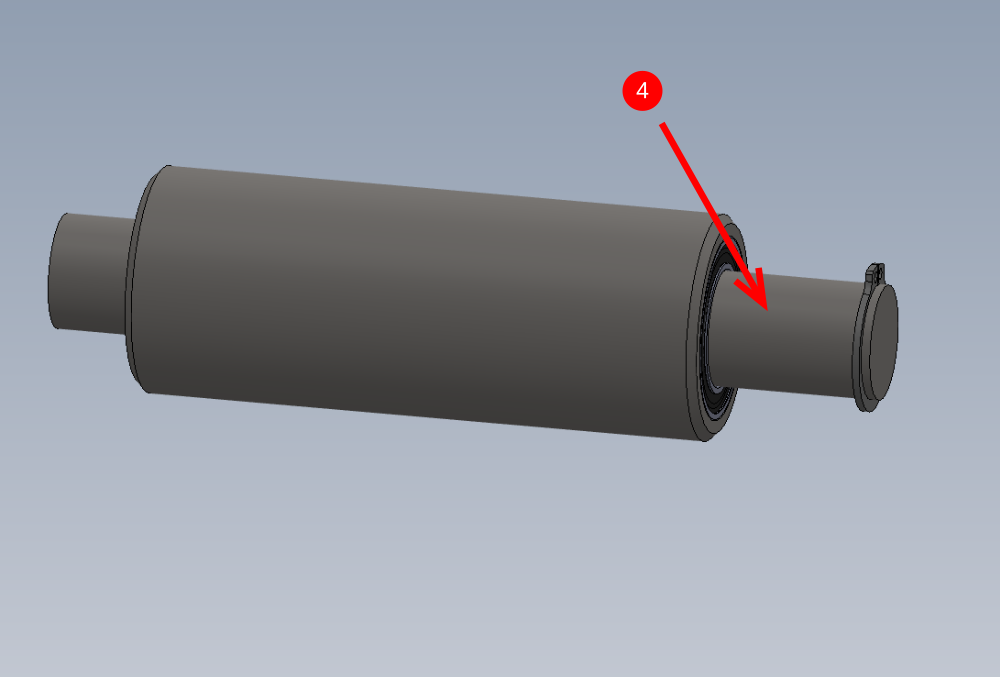
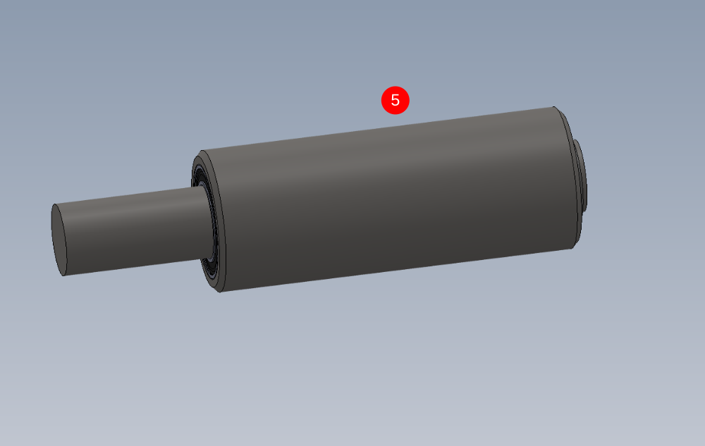
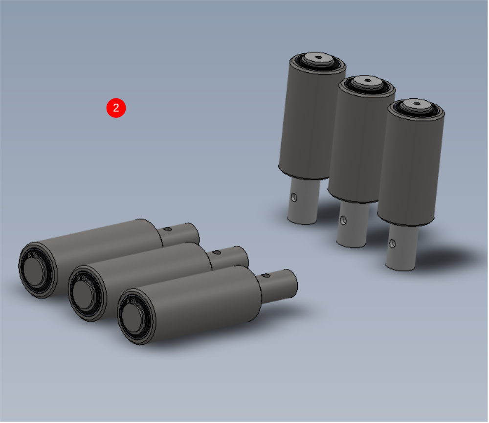
Étape 4 - Add circlip and fit roller
1 Fit 6 off 20mm external circlips to shafts as shown
2 Fit rollers to shafts
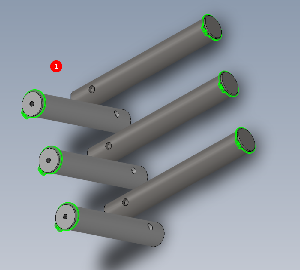
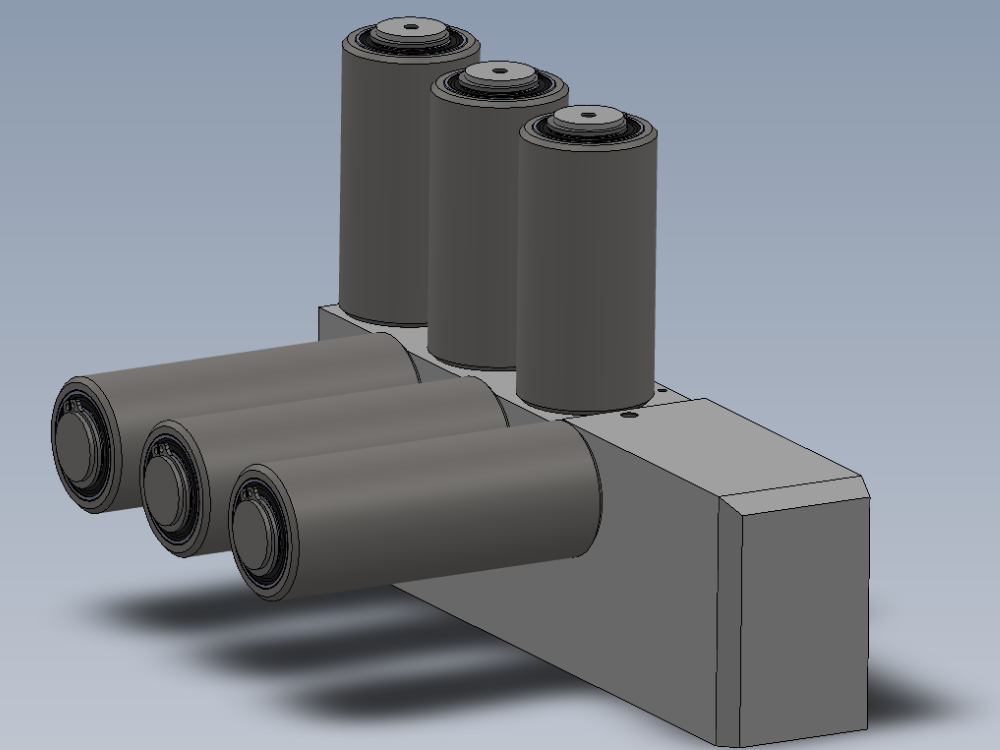
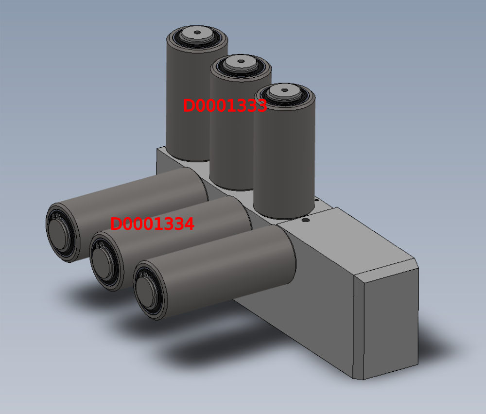
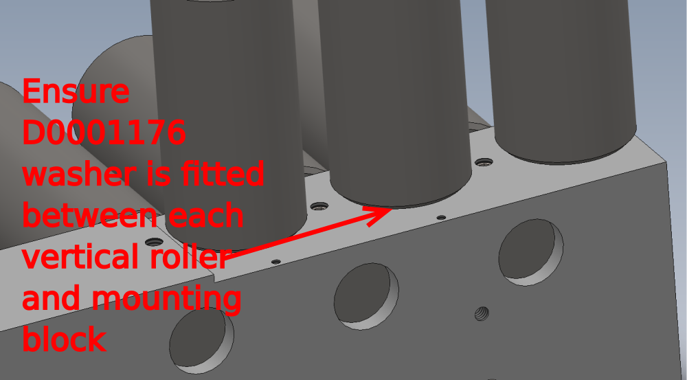
Étape 5 - Mount rollers
Fit rollers to D0007677 Infeed Base Rail (D2972) x 1 as shown and secure with M6 x 10 KCP grubscrews
Ensure dimples in shafts are located correctly to receive grubscrews
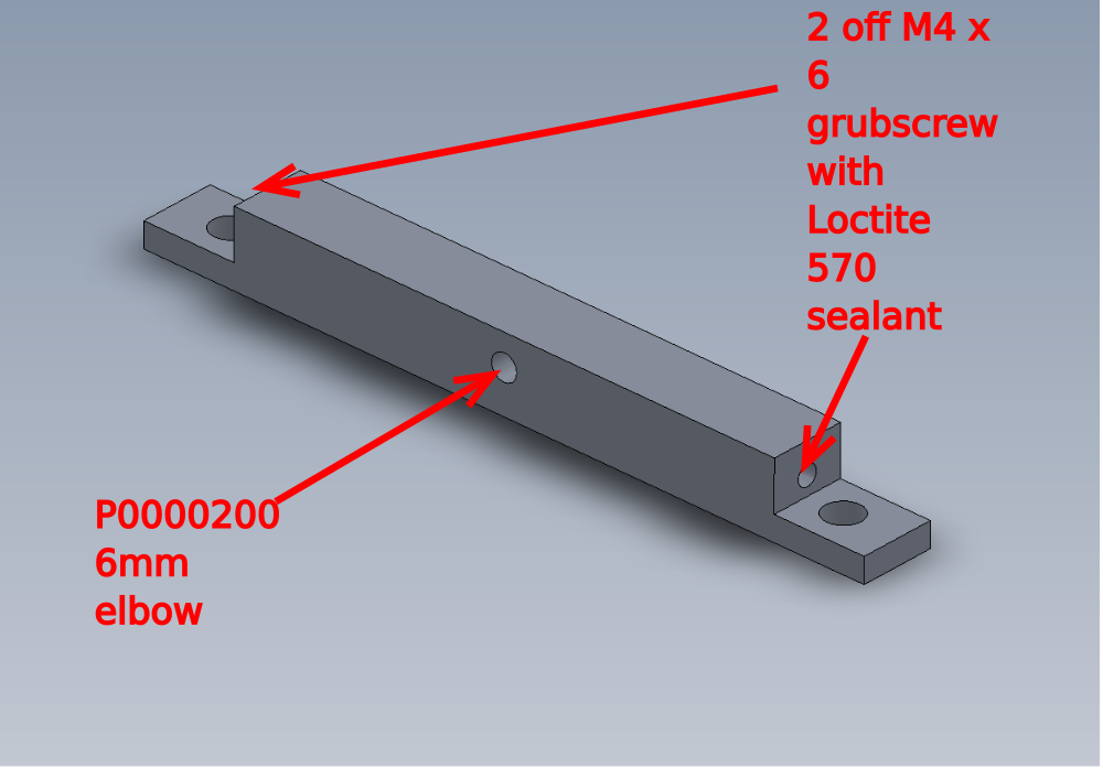
Étape 6 - Assemble Blower rails
Assemble blower rails as shown
1 D0010896
2 D0018097
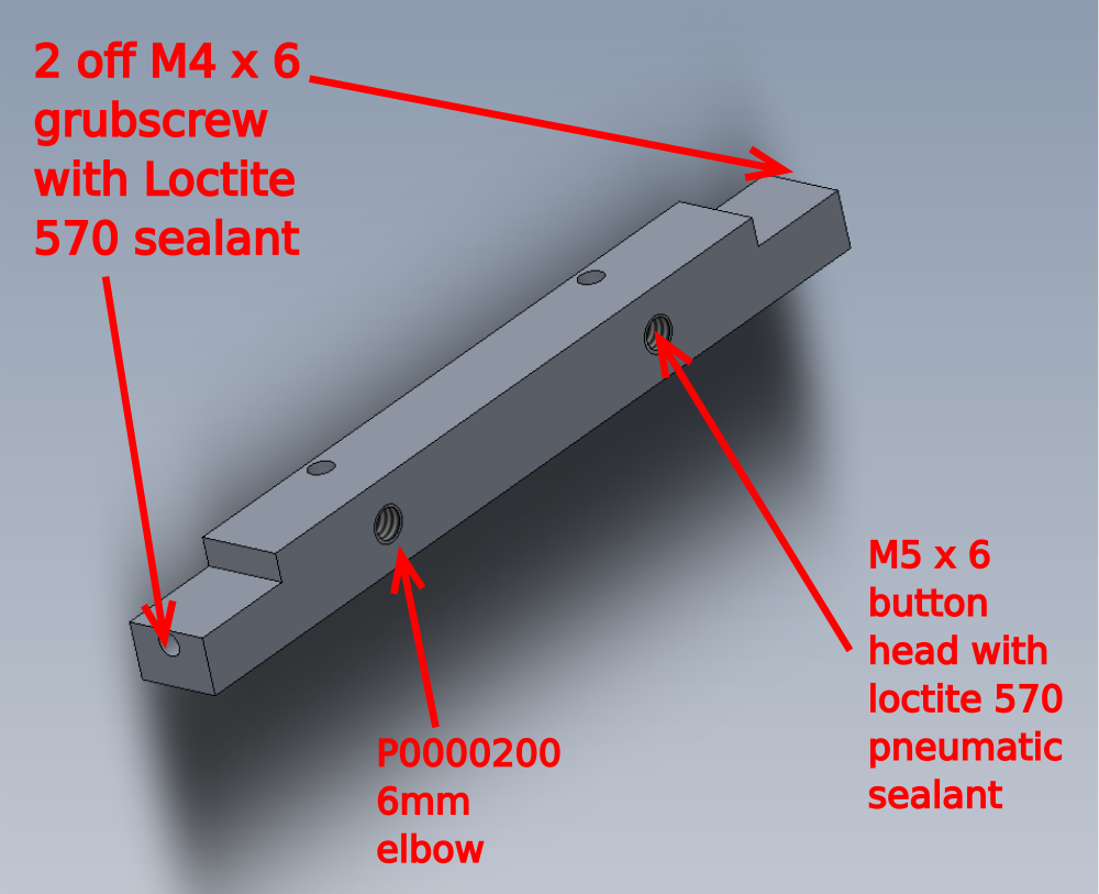
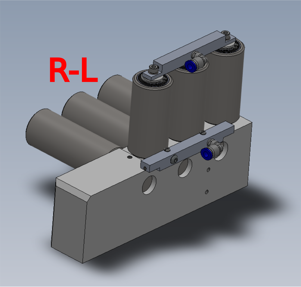
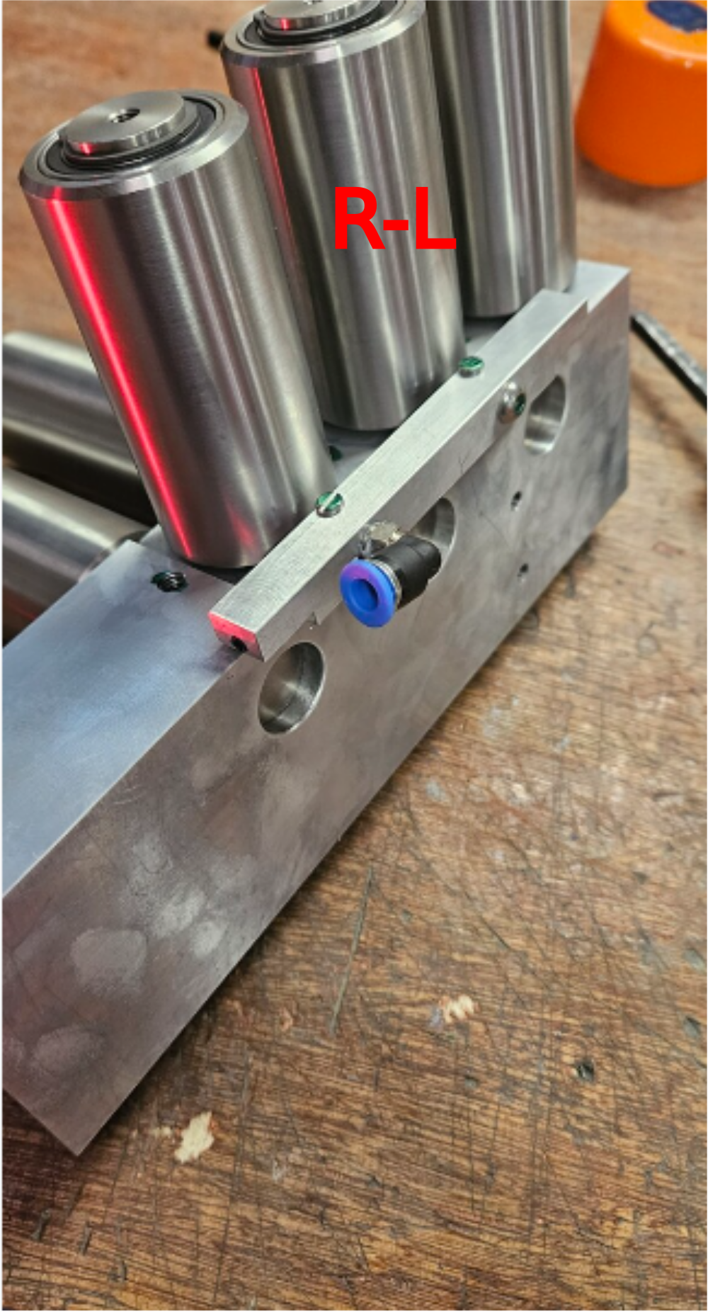
Étape 7 - Mount blower rails
Mount blower rails to roller assembly
Use m3 x 20 pan heads to mount D0010897
Use m5 x 12 socket caps and A form washers to mount D0018096 ( do not use adhesive on these fasteners )
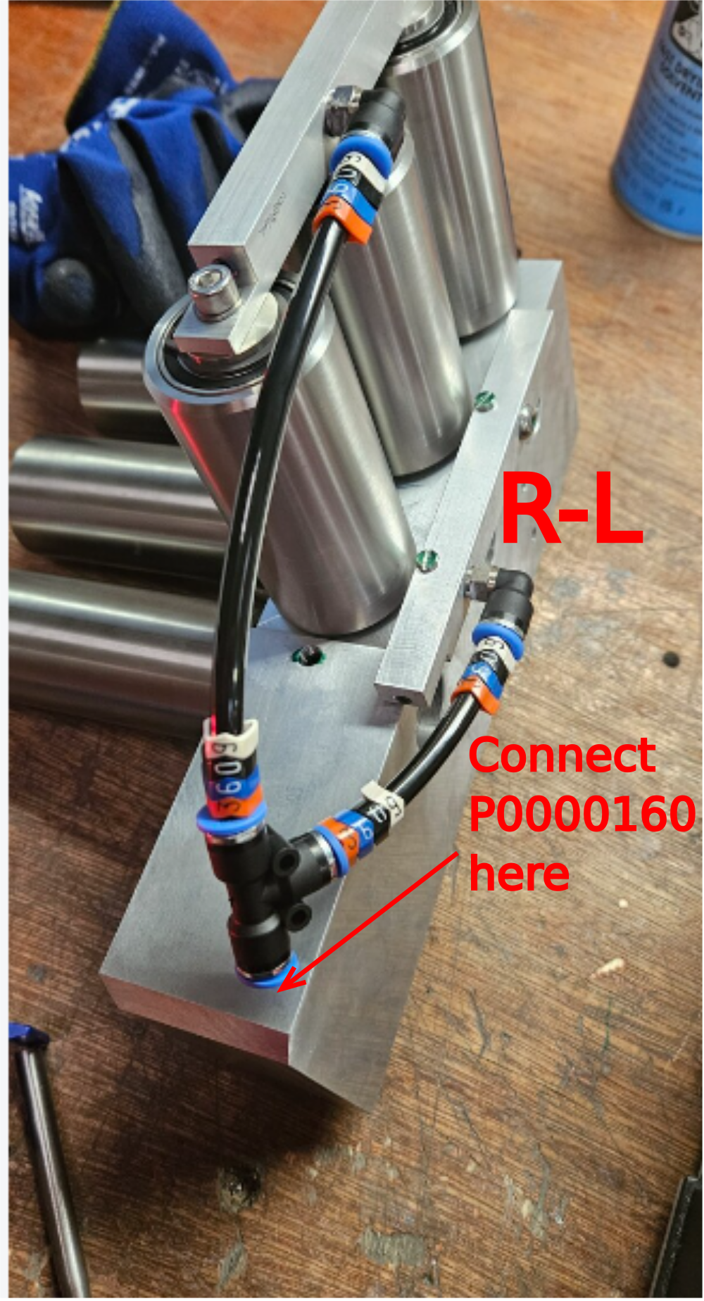
Étape 8 - Fit pipe work
Attach pipework as shown
Pipe identification number is 3609
attach P0000160 flow regulator to pipe port shown

Draft
 Français
 English
 Deutsch
 Español
 Italiano
 Português