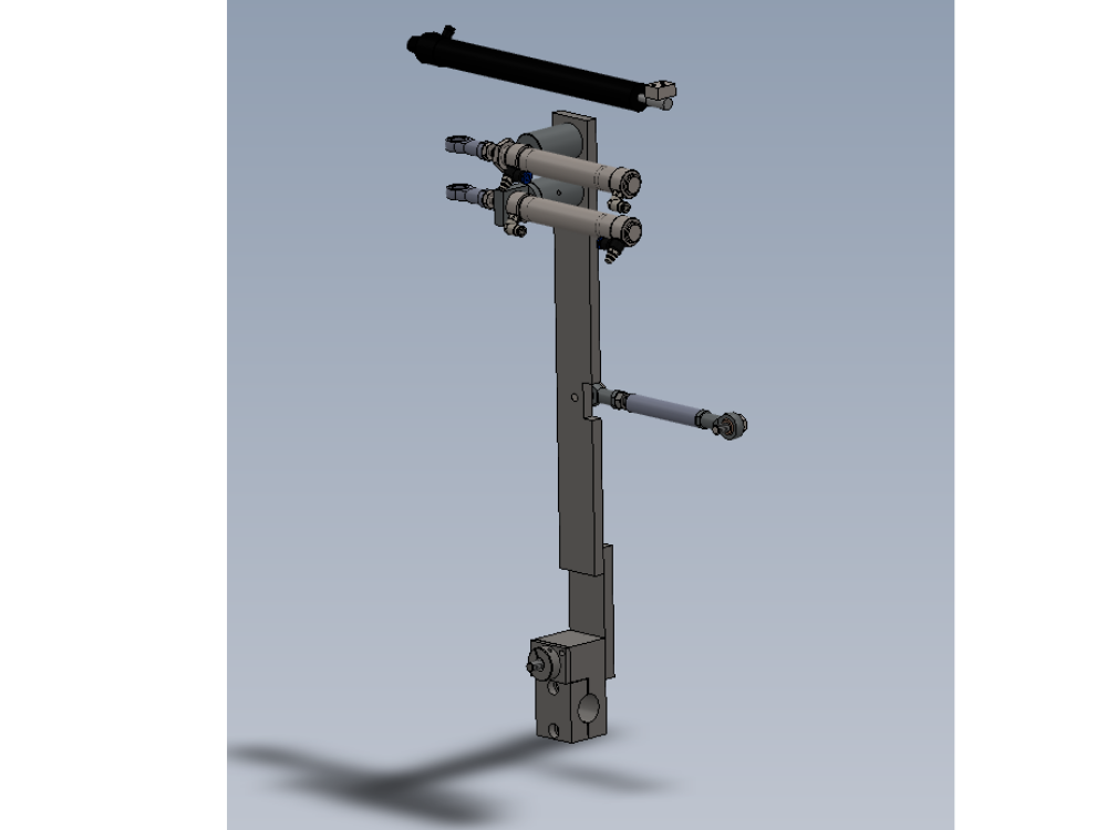
Bench assembly details for centralise components

Difficulté
Moyen
Durée
1 heure(s)
Introduction
Tools Required
standard hex key set
Standard spanner set
Grease gun
Parts Required
B0000005 Angular Contact Bearing 15 I/D 35 O/D 11 Long x 2
B0000065 Bearing Rod End 10mm x 2
D0004363 Middle Link Rod x 1
D0004365 Pivot Clamp x 1
D0004366 Link Clamp Cap x 1
D0004369 Top Link Stud Bolt x 1
D0004370 Middle Link Stud Bolt x 1
D0004393 Lever Joint x 2
D0004394 Joint Shaft x 2
D0004401 Pivot Pin x 1
D0004403 Pivot Pin Nut x 1
D0004406 Retainer Plate x 1
D0004407 Pivot Bearing Spacer x 1
D0004541 Cylinder Swivel End x 2
D0004542 Cylinder Bracket 4542 x 1
D0004622 Centralise Cylinder Spacer x 1
D0004669 Damper Rod End Block x 1
D0004766 Pivot Pin Bolt x 1
H0004367 Centering lever x 1
P0000029 Non Adjustable Damper 100mm
P0000031 Pneumax Microcylinder 25 x 100 Magnetic
P0000049 Cylinder Spherical Bearing M10 x 1.25
P0000295 Elbow Adaptor 6mm - 1/8 BSPT (Metal type)
P0001198 fitting speed controller 1/8 x 6mm tube
Étape 1 - Unless otherwise stated
Use locktite 243 on all fasteners
Use loctite 572 on all threaded pneumatic connection
Pen mark all fasteners to show finalised

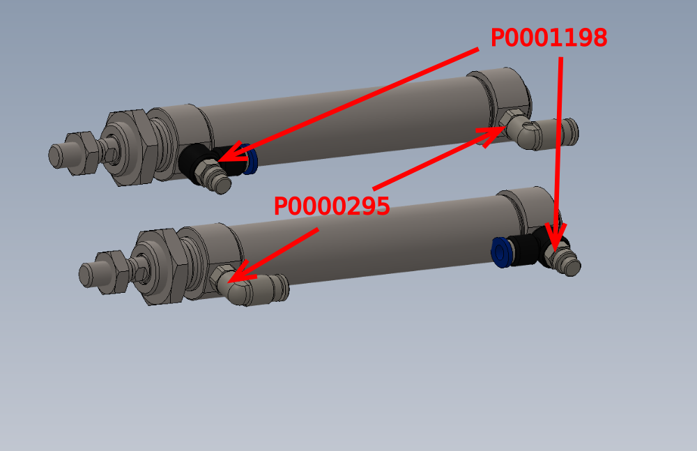
Étape 2 - Assemble cylinders
Assemble 2 off P0000031 Pneumax Microcylinder 25 x 100 Magnetic as show.
Fit 2 off P0000295 Elbow Adaptor 6mm - 1/8 BSPT (Metal type) and 2 off P0001198 fitting speed controller 1/8 x 6mm tube
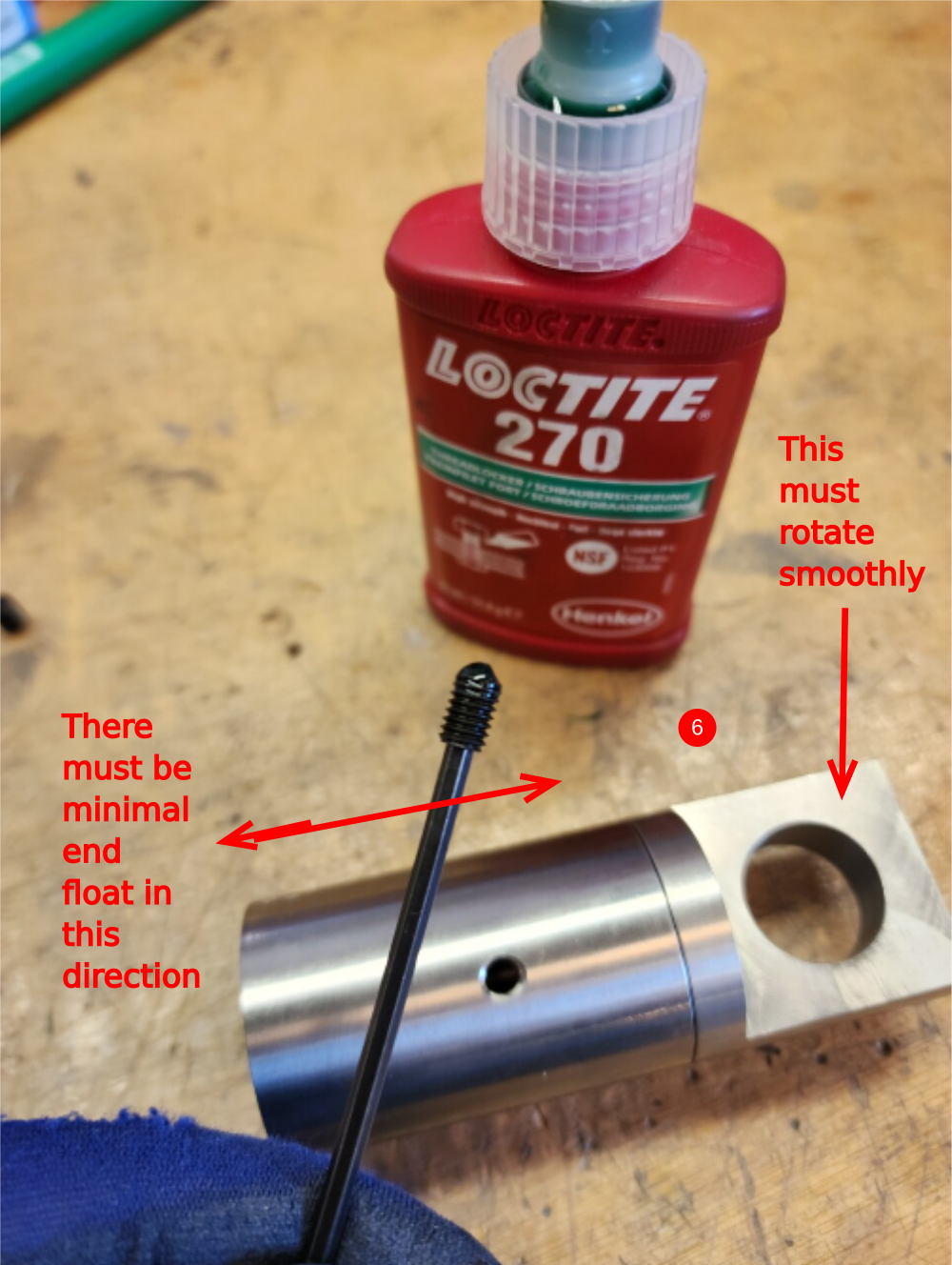
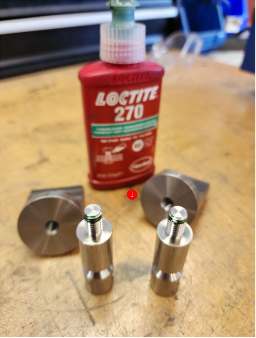
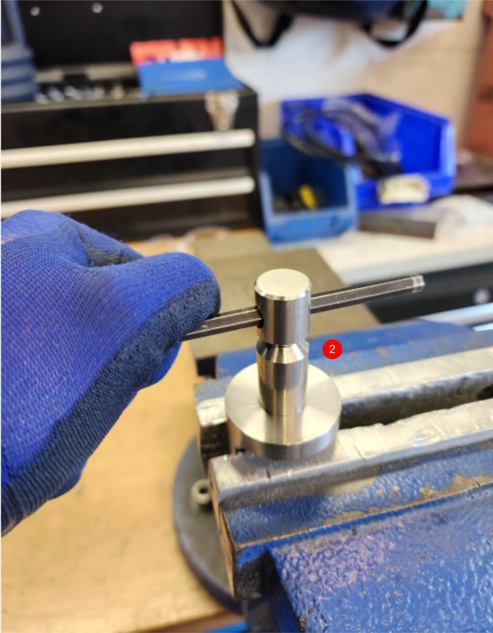
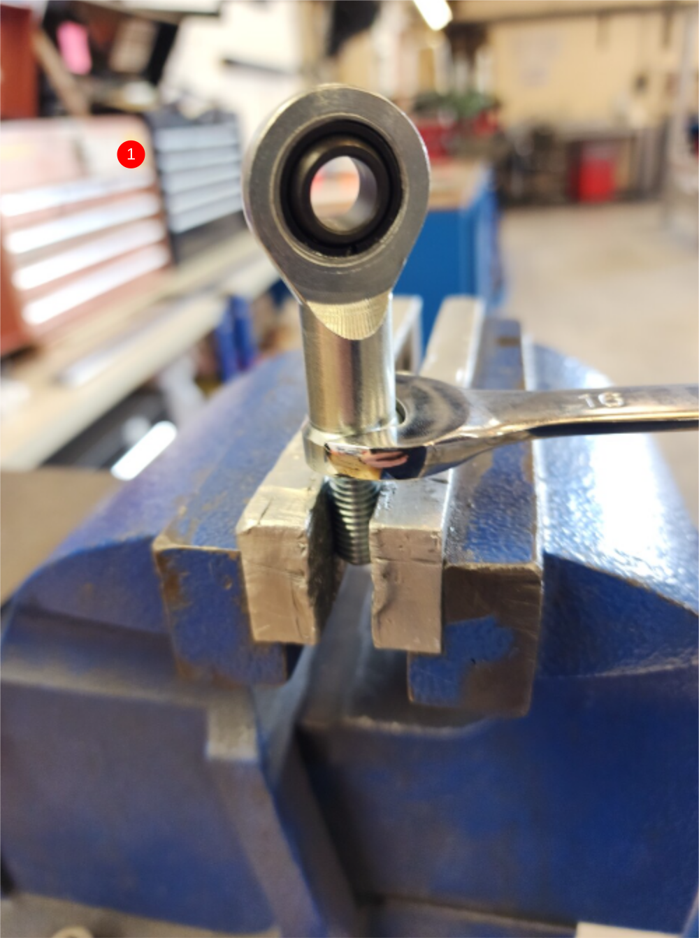
Étape 3 - Assemble swivel mounts
1 Fit D0004393 Lever Joint x 2 using Loctite 270 onto D0004541 Cylinder Swivel End x 2
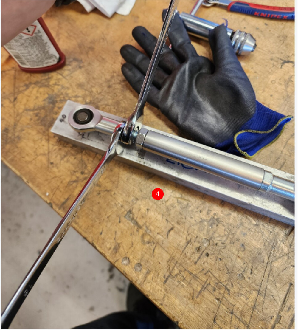
2 Hold as shown in vice and tighten
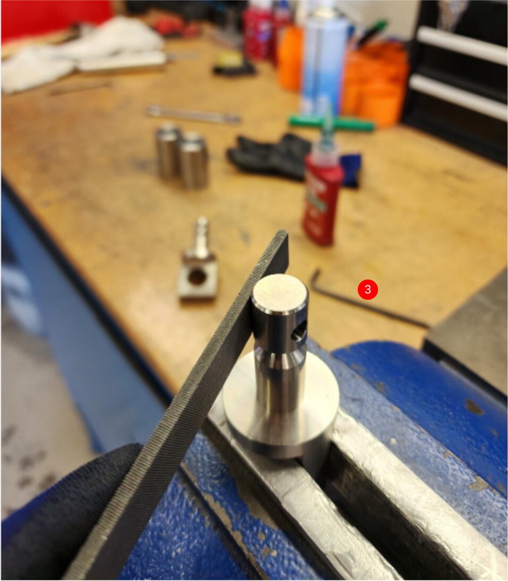
3 Remove any burrs from tightening
4 Check fitment of D0004393 Lever Joint x 2 onto assembled components. Lever joint should fit easily onto assembly and turn freely. Polishing with emery may be required if fit is tight
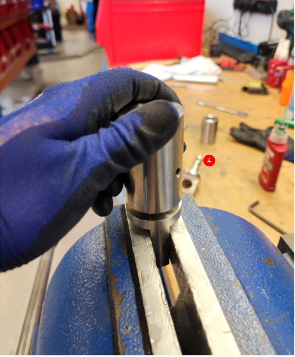
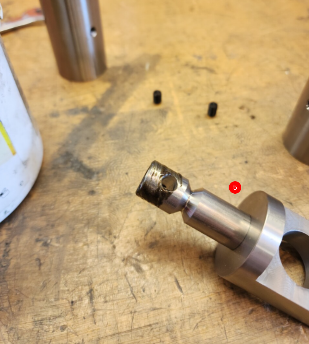
5 Clean and add copper slip as shown to pin , and fit into lever joints
6 Add M6 x 10 pointed grubscrew with Loctite 270 and wind in until the V on the pin has been touched with the grubscrew. adjust grubscrew so rotation is possible but no end float is present
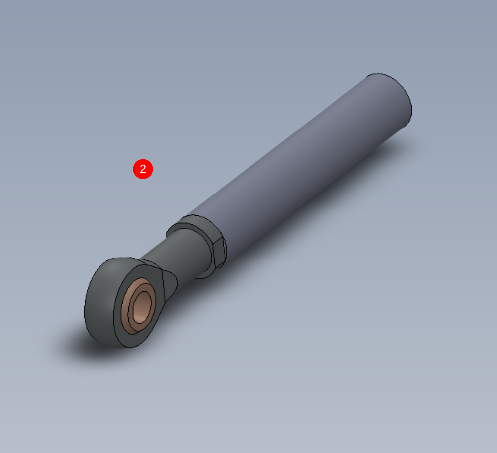
Étape 4 - Assemble tie rod
1 Attach B0000065 Bearing Rod End to D0004370 Middle Link Stud Bolt as shown using Loctite 270
2 Fit to D0004363 Middle Link Rod using Loctite 270 and tighten fully
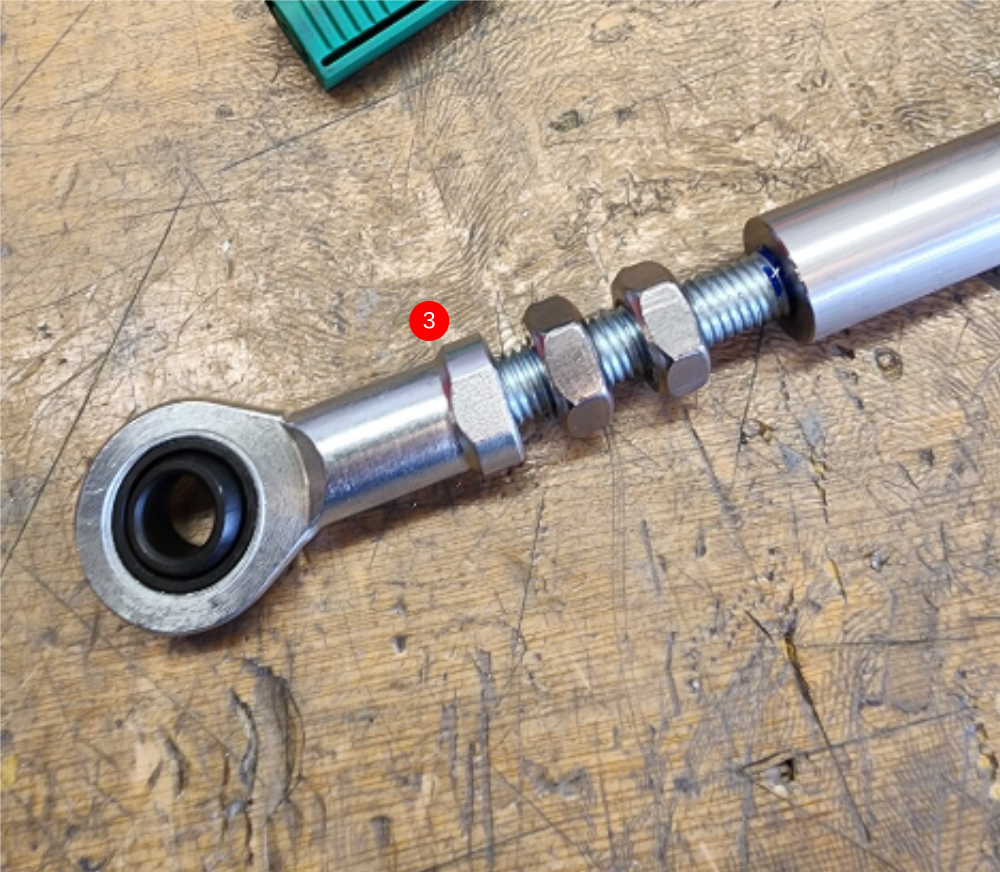
3 Assemble B0000065 Bearing Rod End onto D0004369 Top Link Stud Bolt using loctite 243, then add 2 off M10 standard nuts as shown. Add Loctite 243 onto exposed thread and wind into D0004363 Middle Link Rod
4 Use pitching jig to correctly set pitch of tie bar assembly. Slightly tension assembly on jig, then remove and add final tension to all M10 nuts
Étape 5 - Check fitment
Check fitment of D0004401 Pivot Pin and D0004403 Pivot Pin Nut
Nut should spin down shaft thread with little resistance
Report any anomaly to supervisor

Étape 6 - Assemble pivot assembly
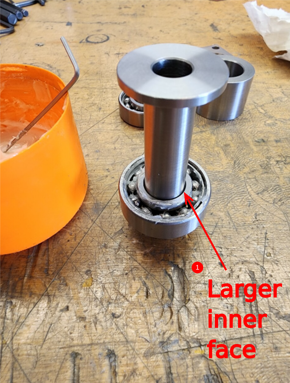
1 Fit B0000005 Angular Contact Bearing to D0004401 Pivot Pin as shown. Ensure bearing is orientated the correct way. Larger inner face should be as shown .
Ensure correct bearing fitment is present . If bearing is a loose fit, loctite 641 should be used . If fitment is to tight, inspect parts to drawing for discrepancies
Lubricate bearing with grease
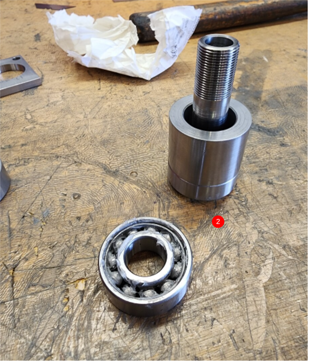
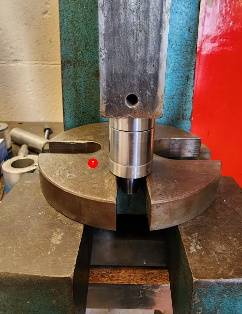
2 Fit D0004407 Pivot Bearing Spacer and second B0000005 Angular Contact Bearing, again observing orientation ( second bearing is fitted opposite to first) Apply grease to second bearing
Draft
 Français
 English
 Deutsch
 Español
 Italiano
 Português