| [version en cours de rédaction] | [version en cours de rédaction] |
| Ligne 5 : | Ligne 5 : | ||
|Categories=Production | |Categories=Production | ||
|Difficulty=Medium | |Difficulty=Medium | ||
| − | |Duration= | + | |Duration=2 |
|Duration-type=hour(s) | |Duration-type=hour(s) | ||
}} | }} | ||
Version actuelle datée du 3 avril 2024 à 12:35
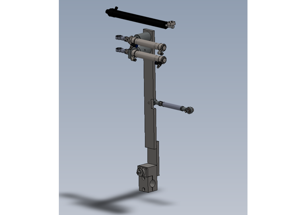
Bench assembly details for centralise components

Difficulté
Moyen
Durée
2 heure(s)
Sommaire
- 1 Introduction
- 2 Étape 1 - Unless otherwise stated
- 3 Étape 2 - Assemble cylinders
- 4 Étape 3 - Assemble swivel mounts
- 5 Étape 4 - Following step has been amended to include new tie rod setting
- 6 Étape 5 - Assemble tie rod
- 7 Étape 6 - Check fitment
- 8 Étape 7 - Assemble pivot assembly
- 9 Étape 8 - Assemble pivot assembly
- 10 Étape 9 - Fit pivot assemble to housing
- 11 Étape 10 - Connect to levering bar
- 12 Étape 11 - Mount cylinders to swivel mounts
- 13 Étape 12 - Attach rod ends
- 14 Étape 13 - Attach to levering bar
- 15 Étape 14 - Assemble damper
- 16 Commentaires
Introduction
Tools Required
standard hex key set
Standard spanner set
Grease gun
Parts Required
B0000005 Angular Contact Bearing 15 I/D 35 O/D 11 Long x 2
B0000065 Bearing Rod End 10mm x 2
D0004363 Middle Link Rod x 1
D0004365 Pivot Clamp x 1
D0004366 Link Clamp Cap x 1
D0004369 Top Link Stud Bolt x 1
D0004370 Middle Link Stud Bolt x 1
D0004393 Lever Joint x 2
D0004394 Joint Shaft x 2
D0004401 Pivot Pin x 1
D0004403 Pivot Pin Nut x 1
D0004406 Retainer Plate x 1
D0004541 Cylinder Swivel End x 2
D0004542 Cylinder Bracket 4542 x 1
D0004622 Centralise Cylinder Spacer x 1
D0004669 Damper Rod End Block x 1
D0004766 Pivot Pin Bolt x 1
H0004367 Centering lever x 1
P0000029 Non Adjustable Damper 100mm x 1
P0000031 Pneumax Microcylinder 25 x 100 Magnetic x 2
P0000049 Cylinder Spherical Bearing M10 x 1.25 x 2
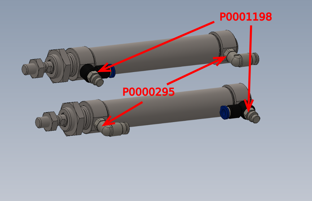
P0000295 Elbow Adaptor 6mm - 1/8 BSPT (Metal type) x 2
P0001198 fitting speed controller 1/8 x 6mm tube x 2
Étape 1 - Unless otherwise stated
Use locktite 243 on all fasteners
Use loctite 572 on all threaded pneumatic connection
Pen mark all fasteners to show finalised

Étape 2 - Assemble cylinders
Assemble 2 off P0000031 Pneumax Microcylinder 25 x 100 Magnetic as show.
Fit 2 off P0000295 Elbow Adaptor 6mm - 1/8 BSPT (Metal type) and 2 off P0001198 fitting speed controller 1/8 x 6mm tube


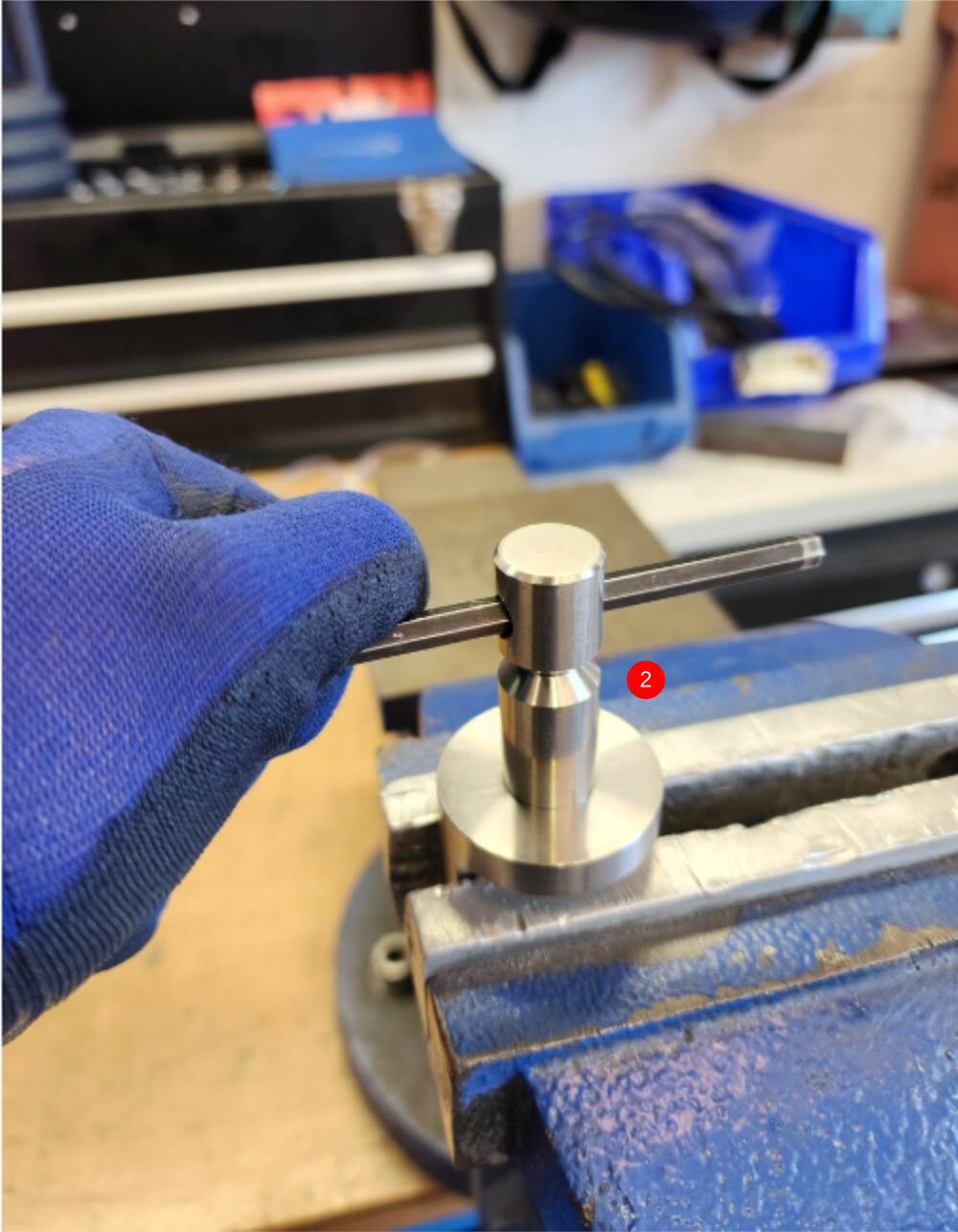
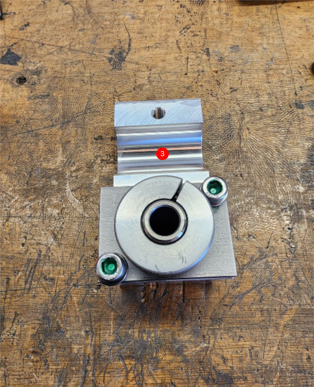
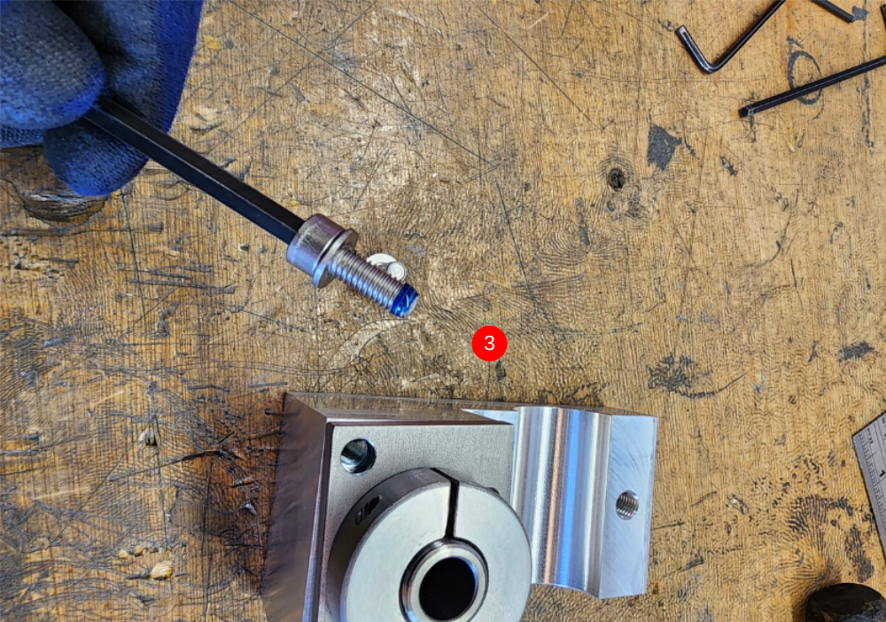
Étape 3 - Assemble swivel mounts
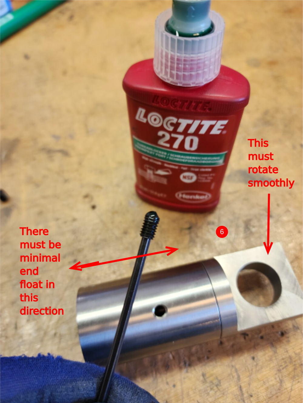
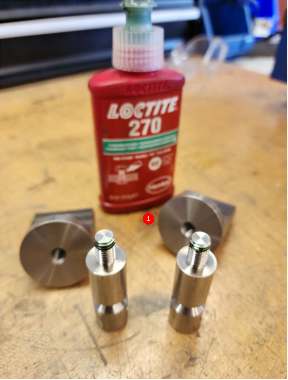
1 Fit D0004393 Lever Joint x 2 using Loctite 270 onto D0004541 Cylinder Swivel End x 2
2 Hold as shown in vice and tighten
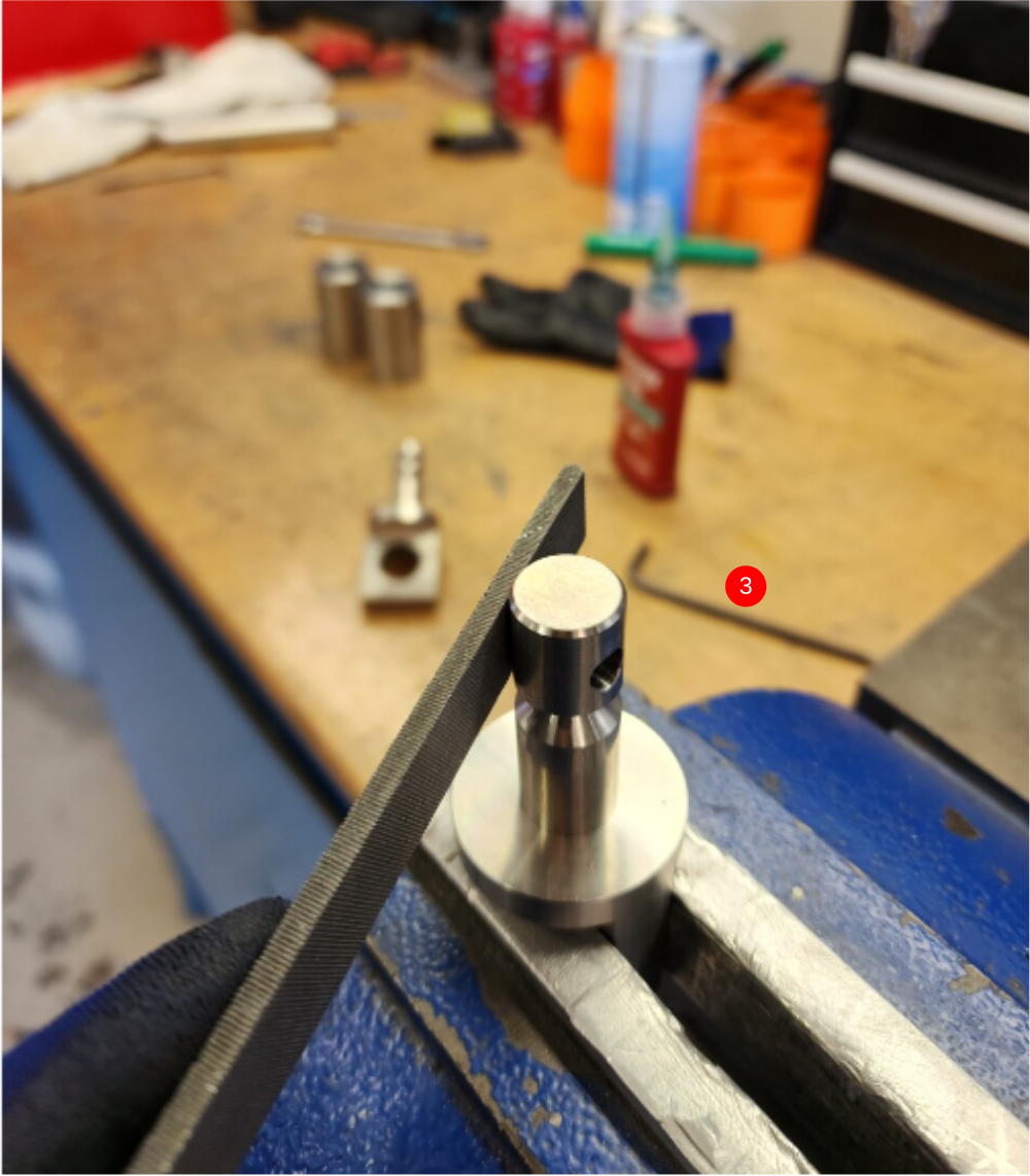
3 Remove any burrs from tightening
4 Check fitment of D0004393 Lever Joint x 2 onto assembled components. Lever joint should fit easily onto assembly and turn freely. Polishing with emery may be required if fit is tight
5 Clean and add copper slip as shown to pin , and fit into lever joints
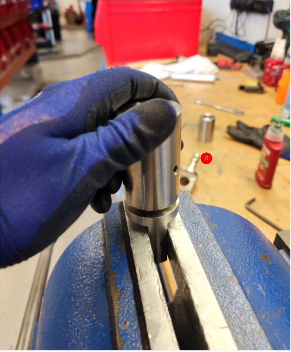
6 Add M6 x 10 pointed grubscrew with Loctite 270 and wind in until the V on the pin has been touched with the grubscrew. adjust grubscrew so rotation is possible but no end float is present
Étape 4 - Following step has been amended to include new tie rod setting
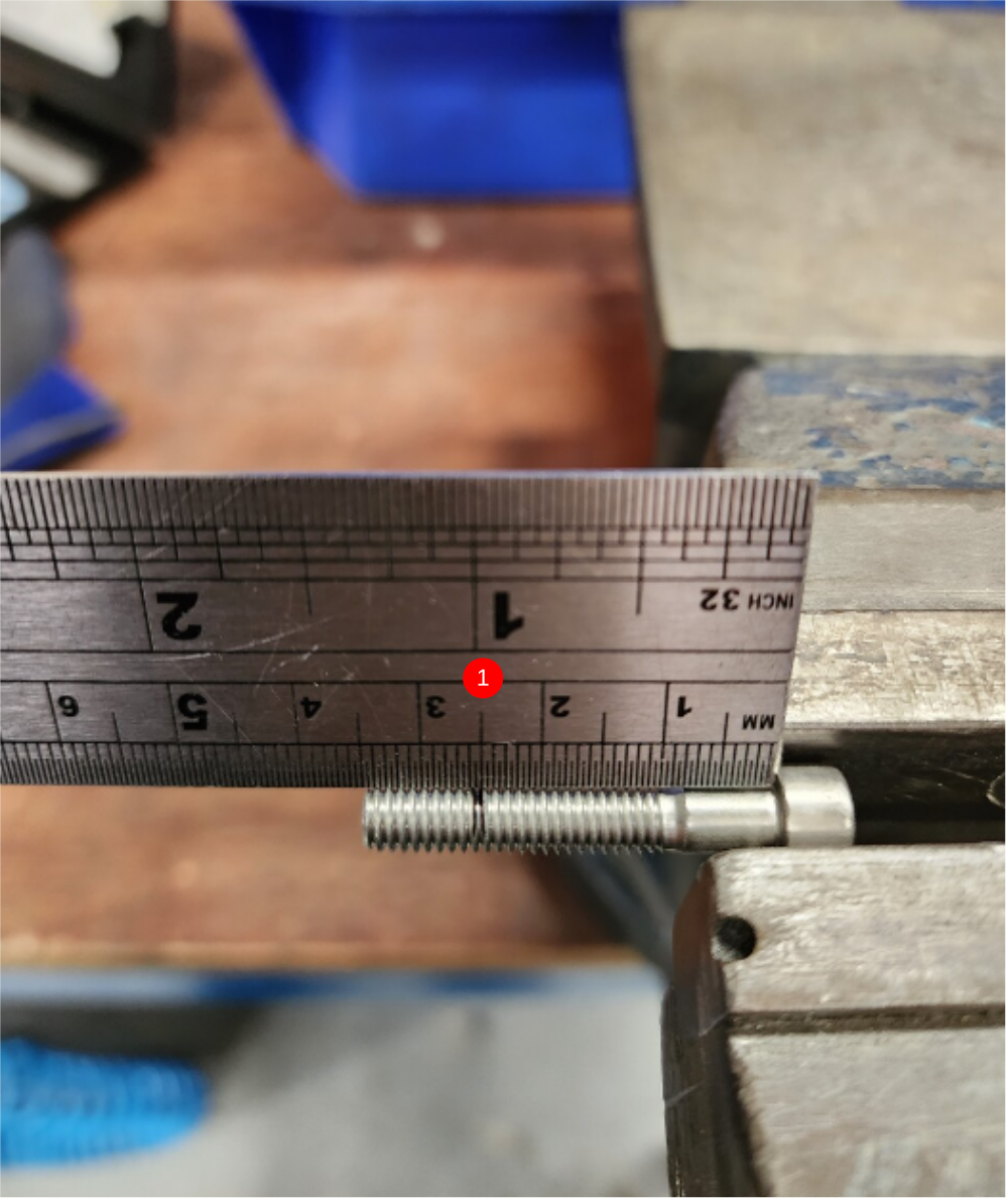
Tie rod should be reduced in length by 1.5mm (1 full turn of rod end)
This should be done after initial setting on set up jig

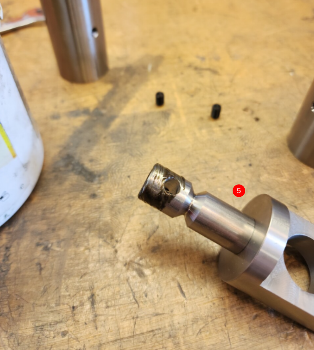
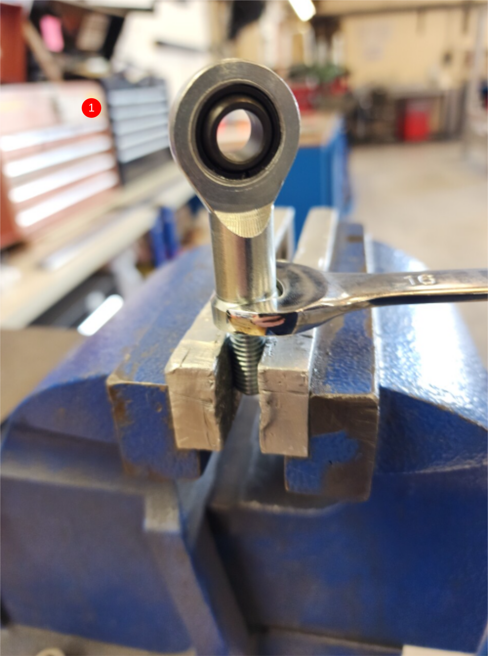
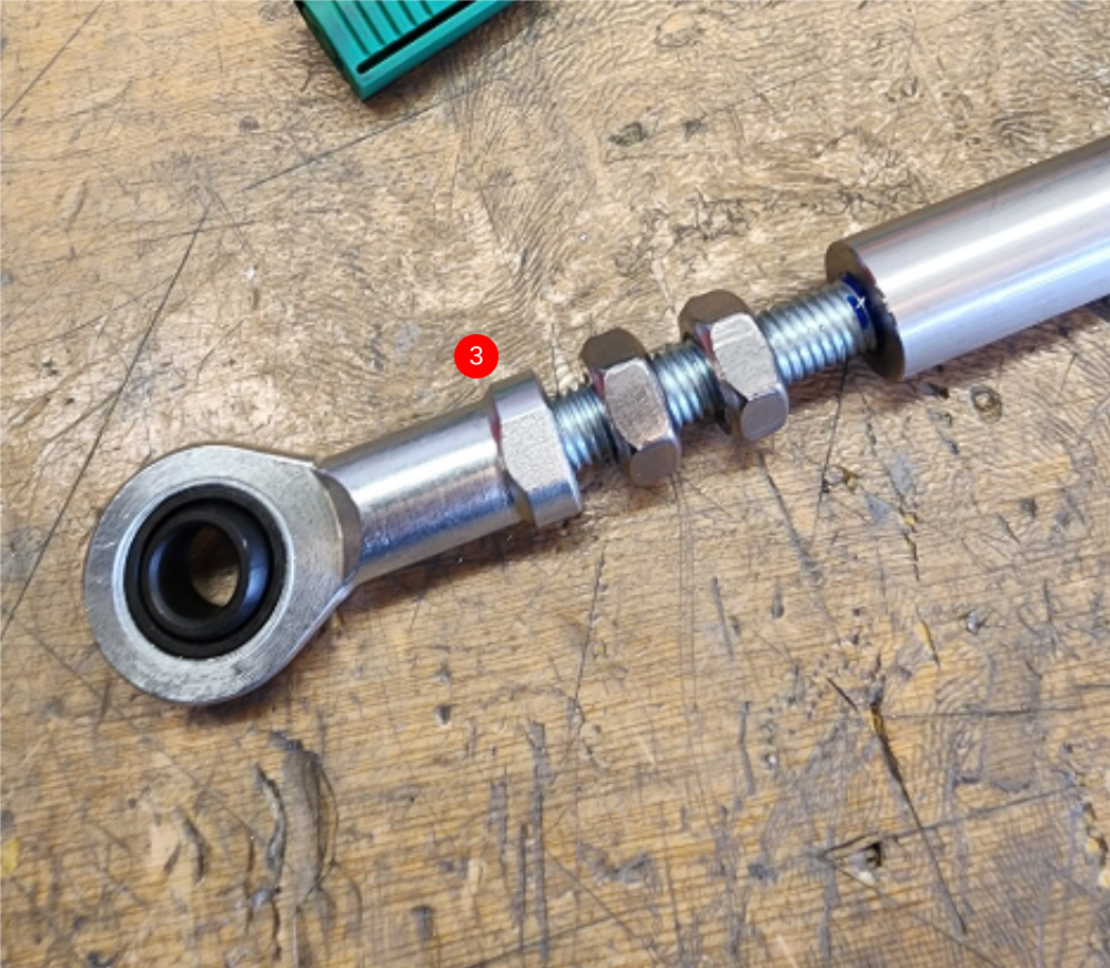
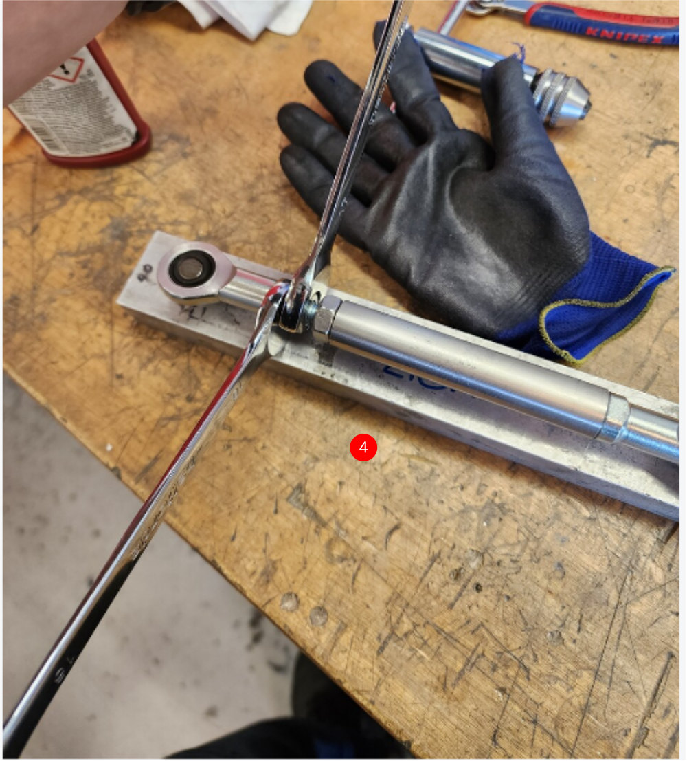
Étape 5 - Assemble tie rod
1 Attach B0000065 Bearing Rod End to D0004370 Middle Link Stud Bolt as shown using Loctite 270
2 Fit to D0004363 Middle Link Rod using Loctite 270 and tighten fully
3 Assemble B0000065 Bearing Rod End onto D0004369 Top Link Stud Bolt using loctite 243, then add 2 off M10 standard nuts as shown. Add Loctite 243 onto exposed thread and wind into D0004363 Middle Link Rod
4 Use pitching jig to correctly set pitch of tie bar assembly. Slightly tension assembly on jig, then remove and add final tension to all M10 nuts

Étape 6 - Check fitment
Check fitment of D0004401 Pivot Pin and D0004403 Pivot Pin Nut
Nut should spin down shaft thread with little resistance
Report any anomaly to supervisor

Étape 7 - Assemble pivot assembly
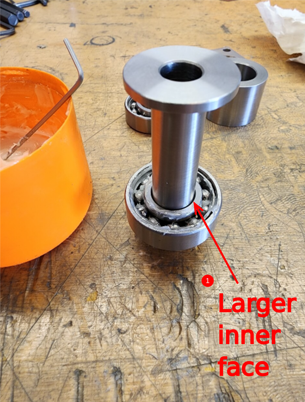
1 Fit B0000005 Angular Contact Bearing to D0004401 Pivot Pin as shown. Ensure bearing is orientated the correct way. Larger inner face should be as shown .
Ensure correct bearing fitment is present . If bearing is a loose fit, loctite 641 should be used . If fitment is to tight, inspect parts to drawing for discrepancies
Lubricate bearing with grease
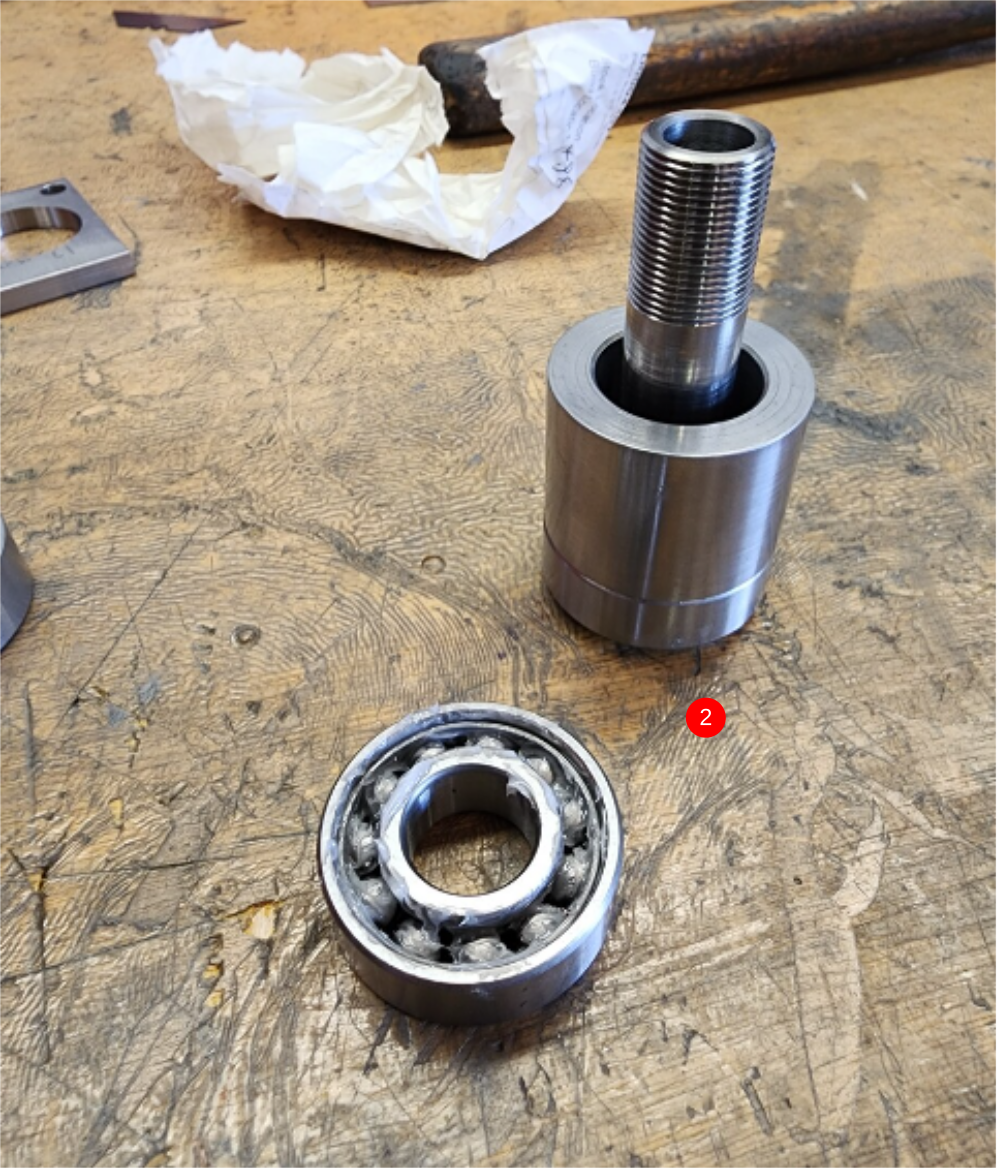
2 Fit D0004407 Pivot Bearing Spacer and second B0000005 Angular Contact Bearing, again observing orientation ( second bearing is fitted opposite to first) Apply grease to second bearing

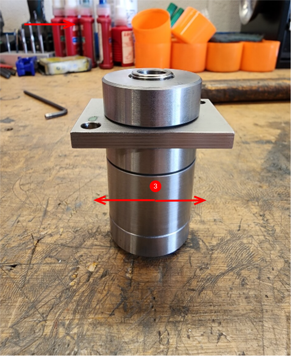
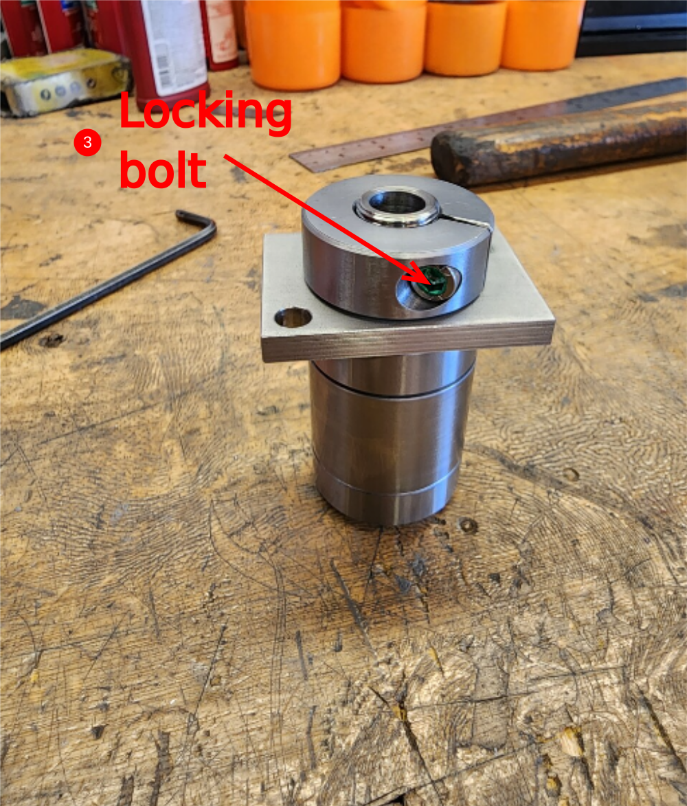
Étape 8 - Assemble pivot assembly
1 Position D0004406 Retainer Plate as shown
2 Fit D0004403 Pivot Pin Nut as shown
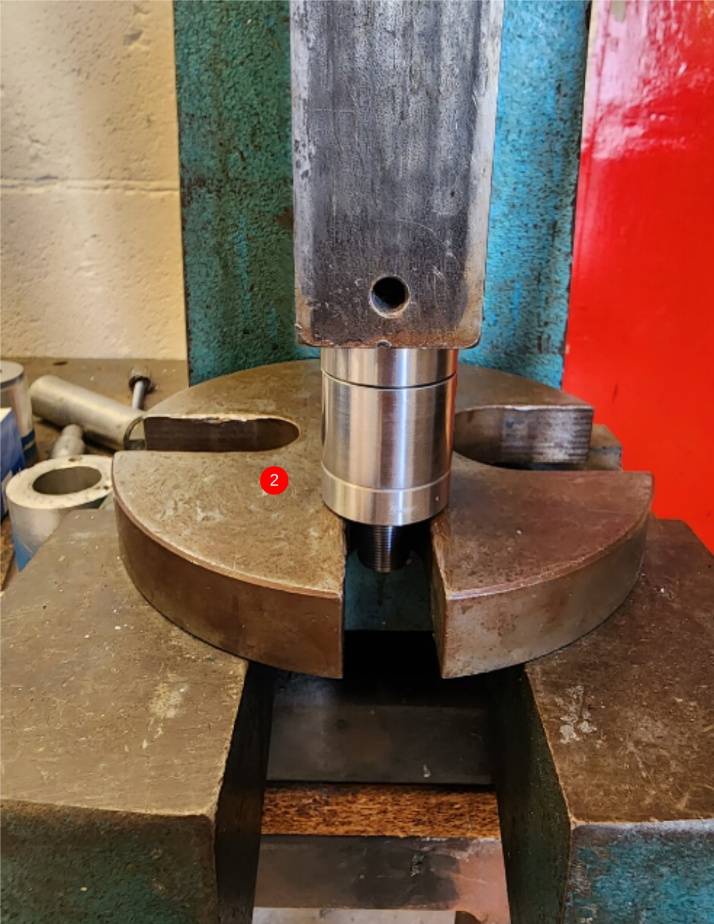
3 Tension nut until centre spacer can just be moved in the indicated direction (please take photo of how this is done with flat head)
4 Add locking bolt M5 x 16 to pivot nut and tighten. Recheck movement indicated, and if this has changed, slacken locking bolt, adjust pivot nut and tension locking bolt again
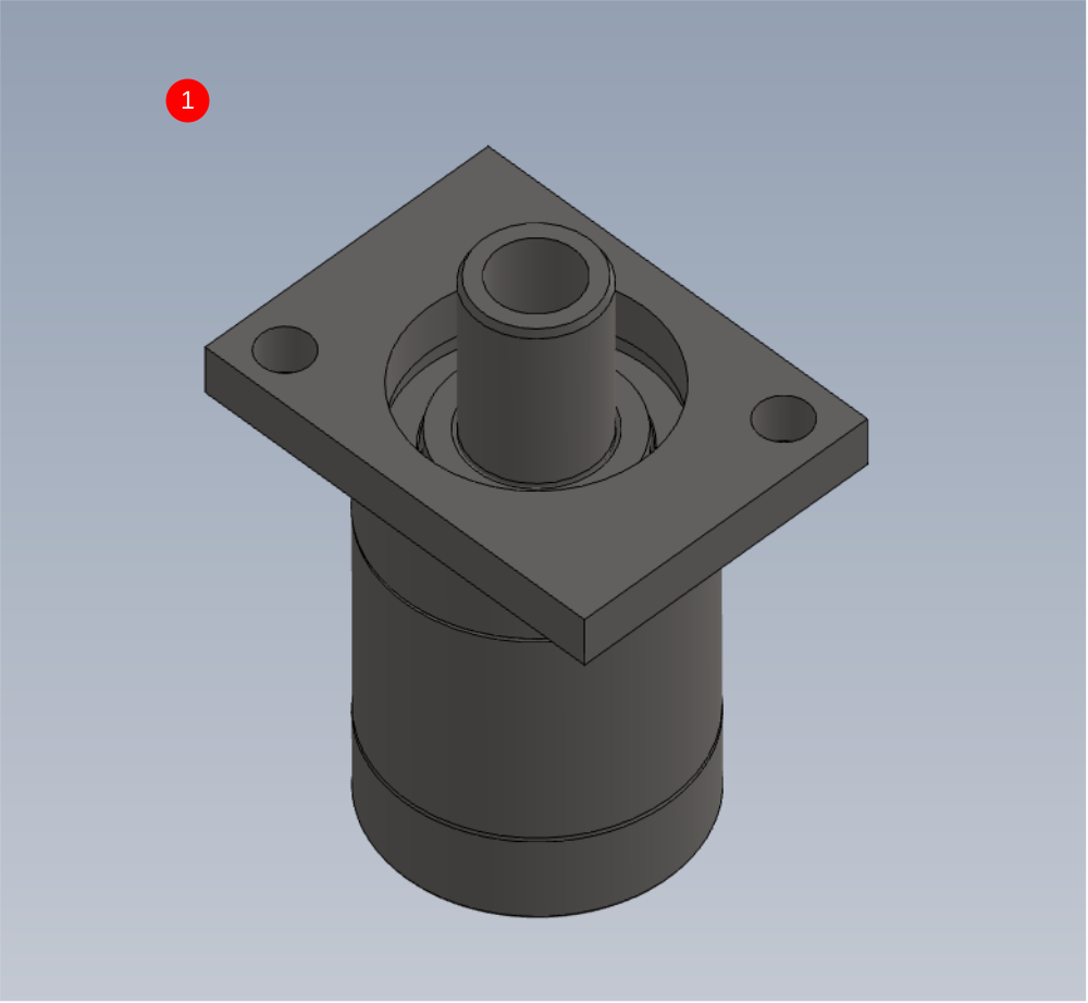
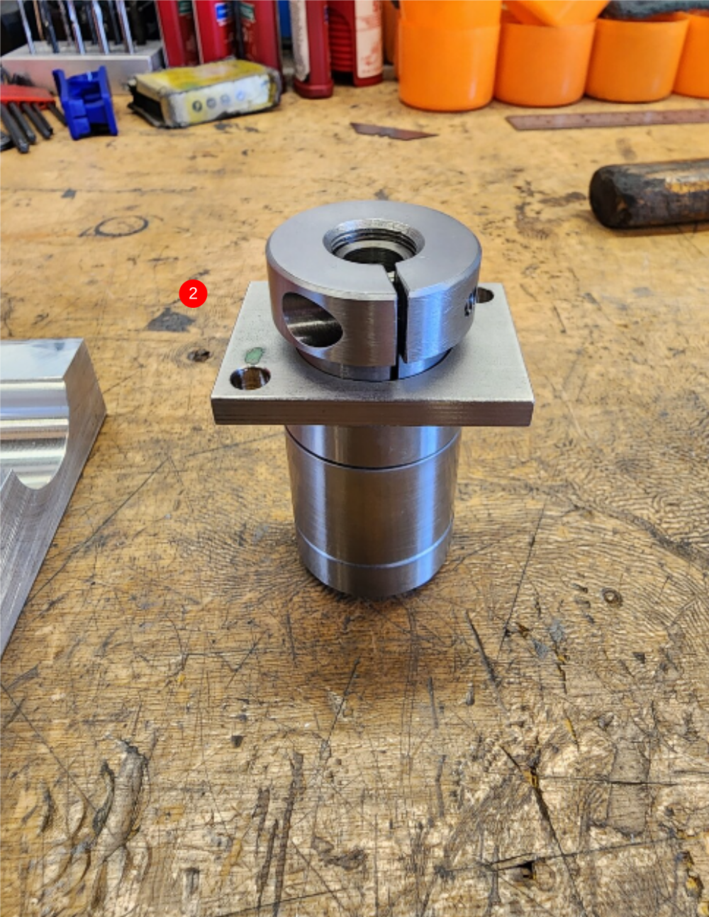

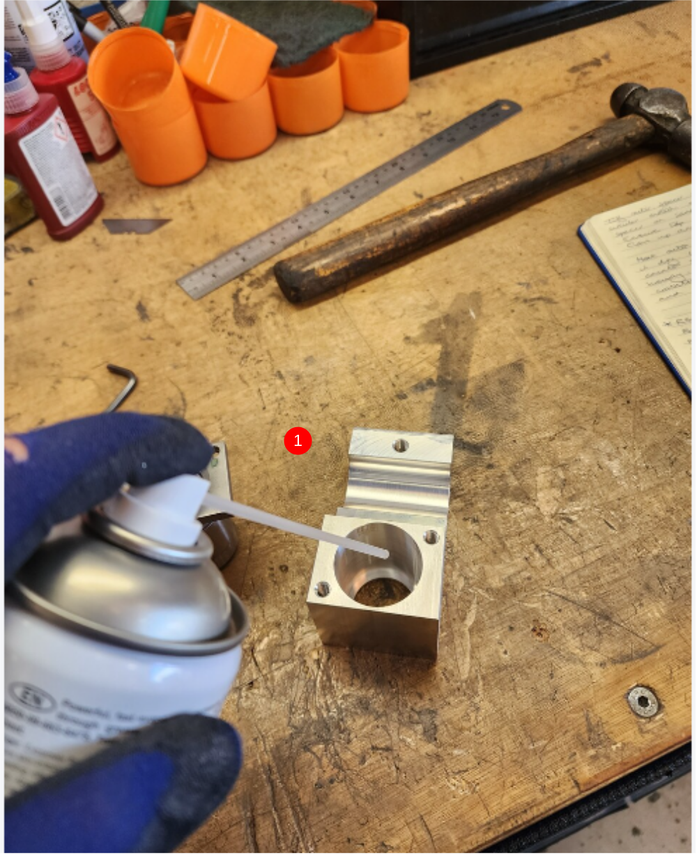
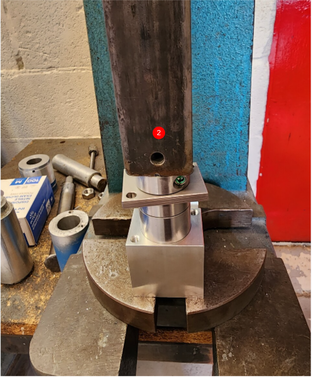
Étape 9 - Fit pivot assemble to housing
1 Degrease bore of D0004365 Pivot Clamp
2 Add a smear of loctite 641 to bore and fit bearing assembly
3 Use 2 off M6 x 16 socket caps with A form washers to finalise
Étape 10 - Connect to levering bar
Connect H0004367 Centering lever to pivot assembly using D0004766 Pivot Pin Bolt as shown . Finalise with M10 standard nut and A form washer
Once assembled, rotation of pivot assembly should be smooth and consistant when turned


Étape 11 - Mount cylinders to swivel mounts
Mount assemblies together as shown ..Ensure air fittings are angled in the same direction as shown.
Finalise locking nuts


Étape 12 - Attach rod ends
Attach 2 off P0000049 Cylinder Spherical Bearing M10 x 1.25 as shown .
Tighten and finalise


Étape 13 - Attach to levering bar
Use M8 x 25 socket caps and A form washers to mount assemblies to centre levering bar as shown


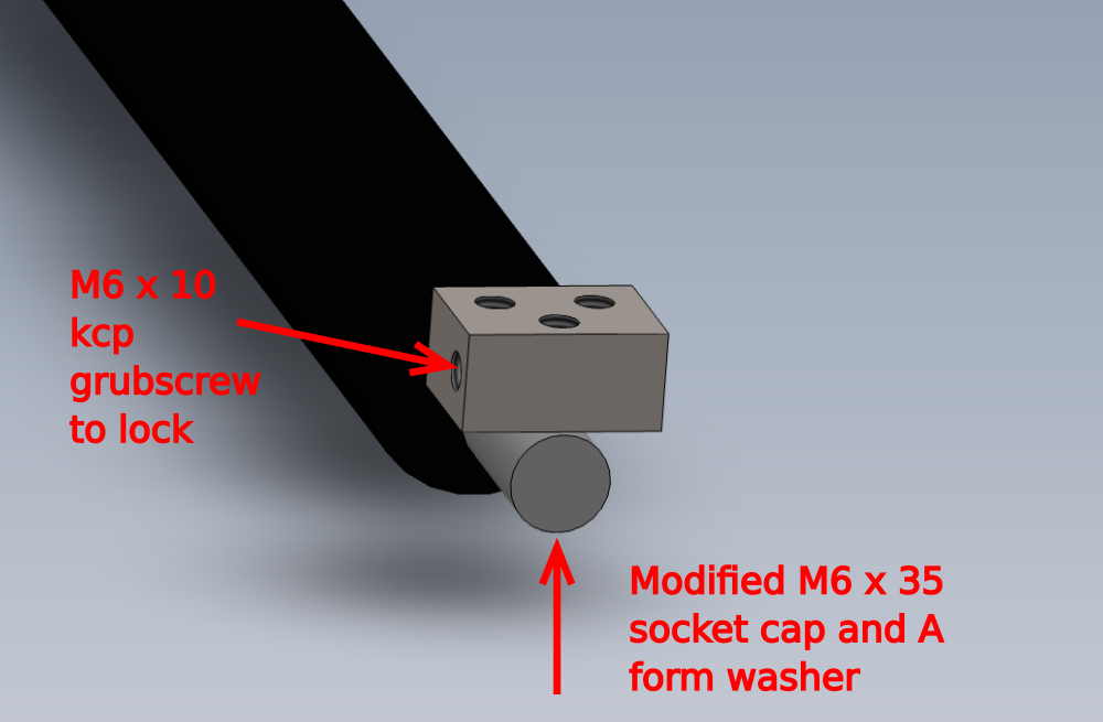
Étape 14 - Assemble damper
1 Modify M6x 35 socket cap and reduce length by 10mm and use to attach damper to rod end block
Assemble P0000029 Non Adjustable Damper 100mm with D0004669 Damper Rod End Block
Ensure rod end block is orientated as shown
Use m6 x 10 kcp grubscrew to secure bolt in rod end block
Rod end block should be able to swivel once assembled and fasteners are tight


Draft
 Français
 English
 Deutsch
 Español
 Italiano
 Português