Alignment and fitment details for cut tables and eject drive

Difficulté
Difficile
Durée
4 heure(s)
Sommaire
- 1 Introduction
- 2 Étape 1 - Unless otherwise stated
- 3 Étape 2 - Level Infeed pad
- 4 Étape 3 - Attach Outfeed Pad
- 5 Étape 4 - Set flatness
- 6 Étape 5 - Set front alignment
- 7 Étape 6 - Check parallel
- 8 Étape 7 - Finalise fasteners
- 9 Étape 8 - Quality check
- 10 Étape 9 - Fit eject cylinder
- 11 Étape 10 - Fit Cylinder fittings
- 12 Étape 11 - Fit energy chain
- 13 Étape 12 - Fit cover fixing bar
- 14 Étape 13 - Fit gap covers
- 15 Étape 14 - Fit ejector cover
- 16 Étape 15 - Set flatness
- 17 Étape 16 - Set front alignment
- 18 Étape 17 - Check parallel
- 19 Étape 18 - Finalise fasteners
- 20 Étape 19 - Fit eject cylinder
- 21 Étape 20 - Fit Cylinder fittings
- 22 Étape 21 - Fit energy chain
- 23 Étape 22 - Fit cover fixing bar
- 24 Étape 23 - Fit gap covers
- 25 Étape 24 - Fit ejector cover
- 26 Étape 25 - Fit ejector cover
- 27 Étape 26 - Quality Check
- 28 Commentaires
Introduction
Tools Required
1 meter straight edge
500mm rule
Standard hex key
Standard spanner set
Feeler gauges
Engineers level
Adjustment shim
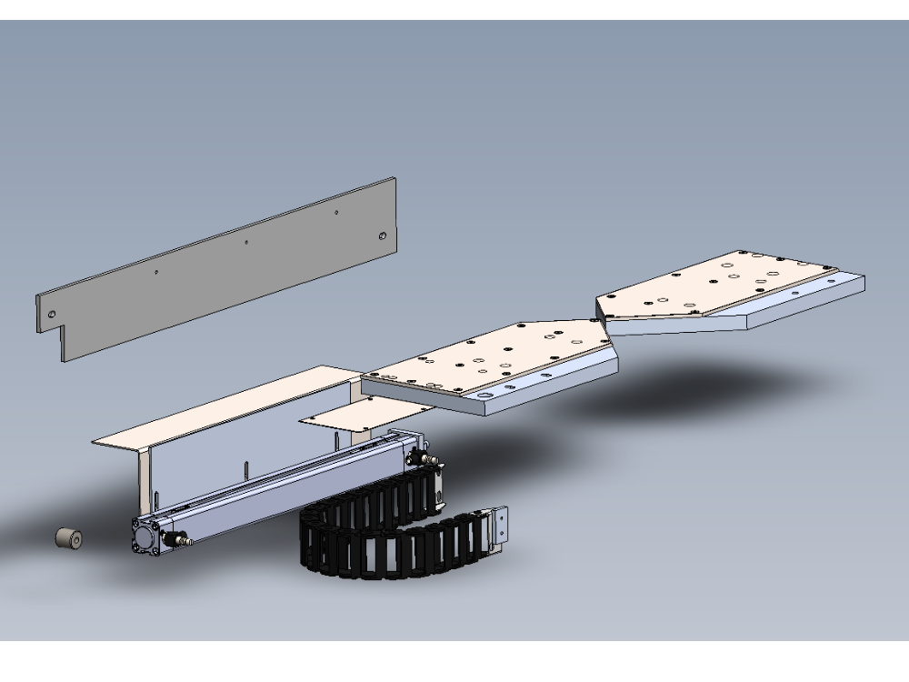
Parts Required
A0001069 Energy Chain Series B15.050 (48mm radius) Openable x 0.5
A0001070 Igus Mounting Br Set for A0001069 Non-Pivot x 1
A0001074 igus mounting bracket set x 1
D0004551 Cylinder Spacer x 1
D0004553 Cover Fixing Bar x 1
D0004554 Bar Spacer Short x 1
D0004555 Bar Spacer Long x 1
D0004769 Ejector Clamp Pad to be made in conjuction with D5121 (5305) x 1
D0004770 Infeed Clamp Pad to be made in conjunction with D5122 (5299) x 1
D0005121 Ejector Clamp Stainless Pads (5306) x 1
D0005122 Infeed Clamp Pad (5300)x 1
D0005199 Ejector Cover x 1
D0005412 Energy Chain Adapter Plate x 1
H0004556 Fixing Bar Gap Cover (5297) x 1
H0004656 Material Trip Stripx 1
P0000368 Extension 1/8 bsp x 22 long x 1
P0000443 Cleanline Cylinder 32 x 450 PN11246 x 1
P0000444 Reed Switch: Pneumax 1580U (5.0m Lead) x 2
P0001198 flow controller 6mm elbow 1/8 x 2Étape 1 - Unless otherwise stated
All bolts to have Loctite 243 adhesive applied unless otherwise stated
All Threaded Pneumatic connections to have Loctite 570 applied
All bolts to be pen marked once adhesive applied and correct tension added

Étape 2 - Level Infeed pad
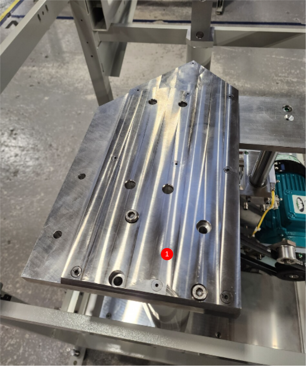
1 Attach Infeed pad using 4 off M8 x 35 socket caps with no adhesive. Only apply medium tension to fasteners
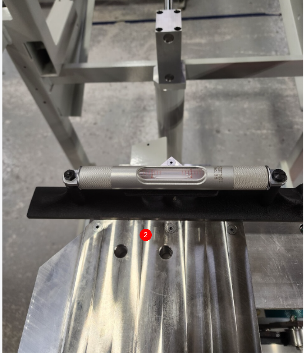
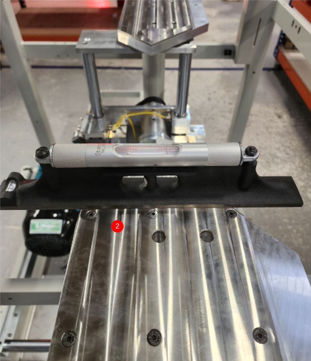
2 Check level in both directions with engineers level
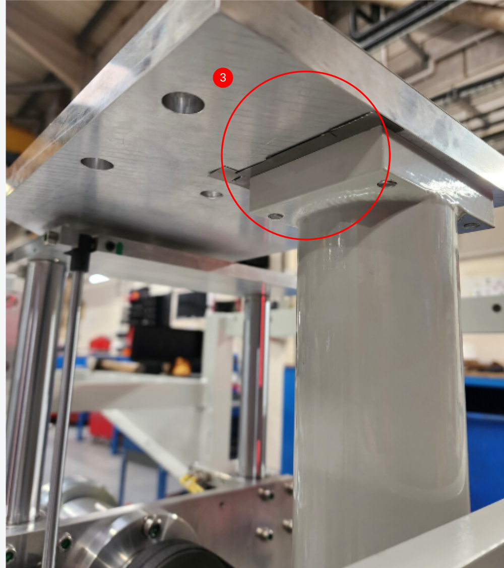
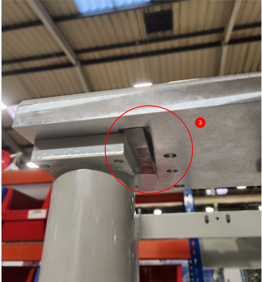
3 Add shim if required to adjust, Shim should be cut width of post where being fitted, and protruding as shown. Ensure shim is pushed against M8 socket caps holding table in position (shims will be trimmed later )
Ensure 4 off M8 fasteners have final tension applied , to ensure accurate representation with shims fitted


Étape 3 - Attach Outfeed Pad
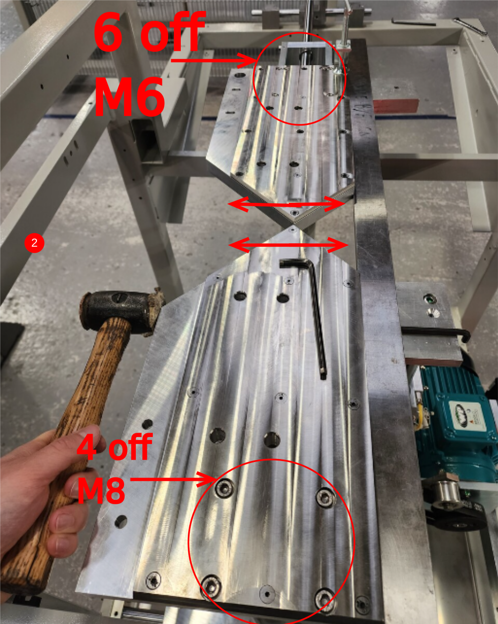
1 Attach Eject pad using 6 off M6 x 30 socket caps, Do not apply adhesive, do not apply final tension
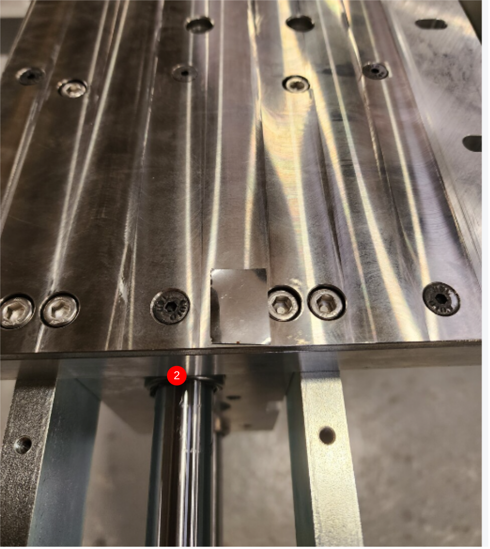
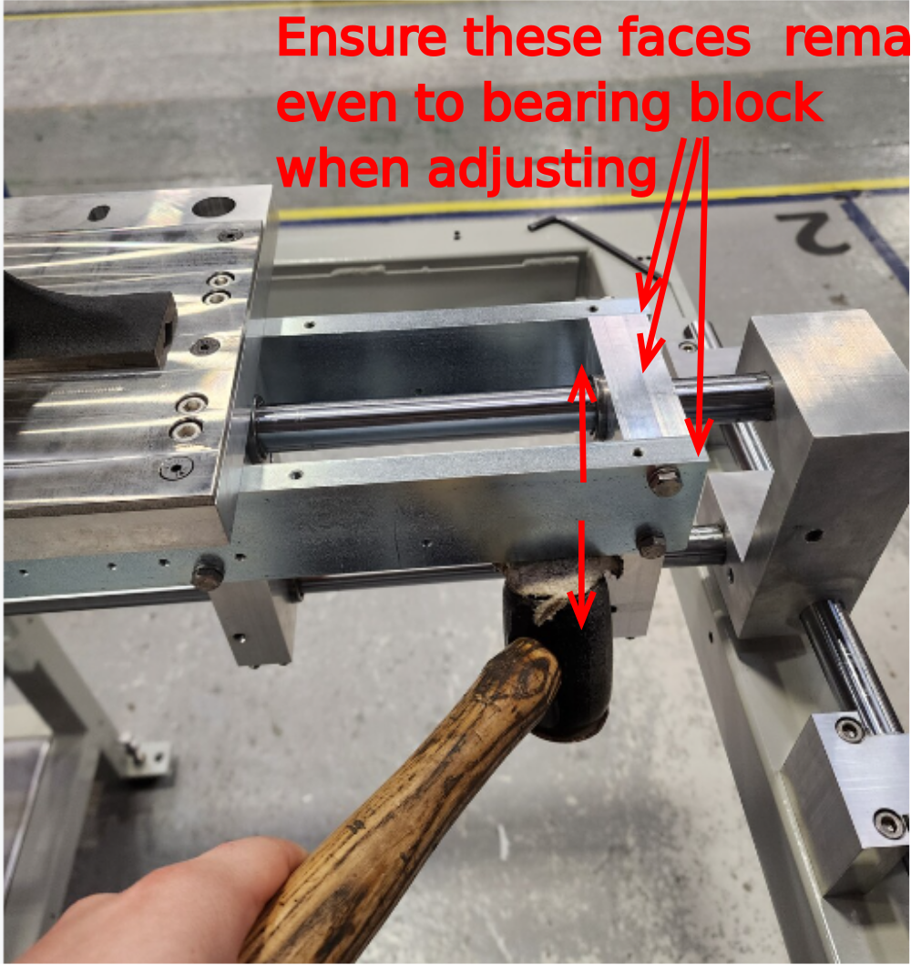
2 Check Y axis level using engineers level. Use shim to adjust if required . Use shim as shown ( shown on top face for position info, shim should be placed between cut table and bearing block according to level adjustment required)
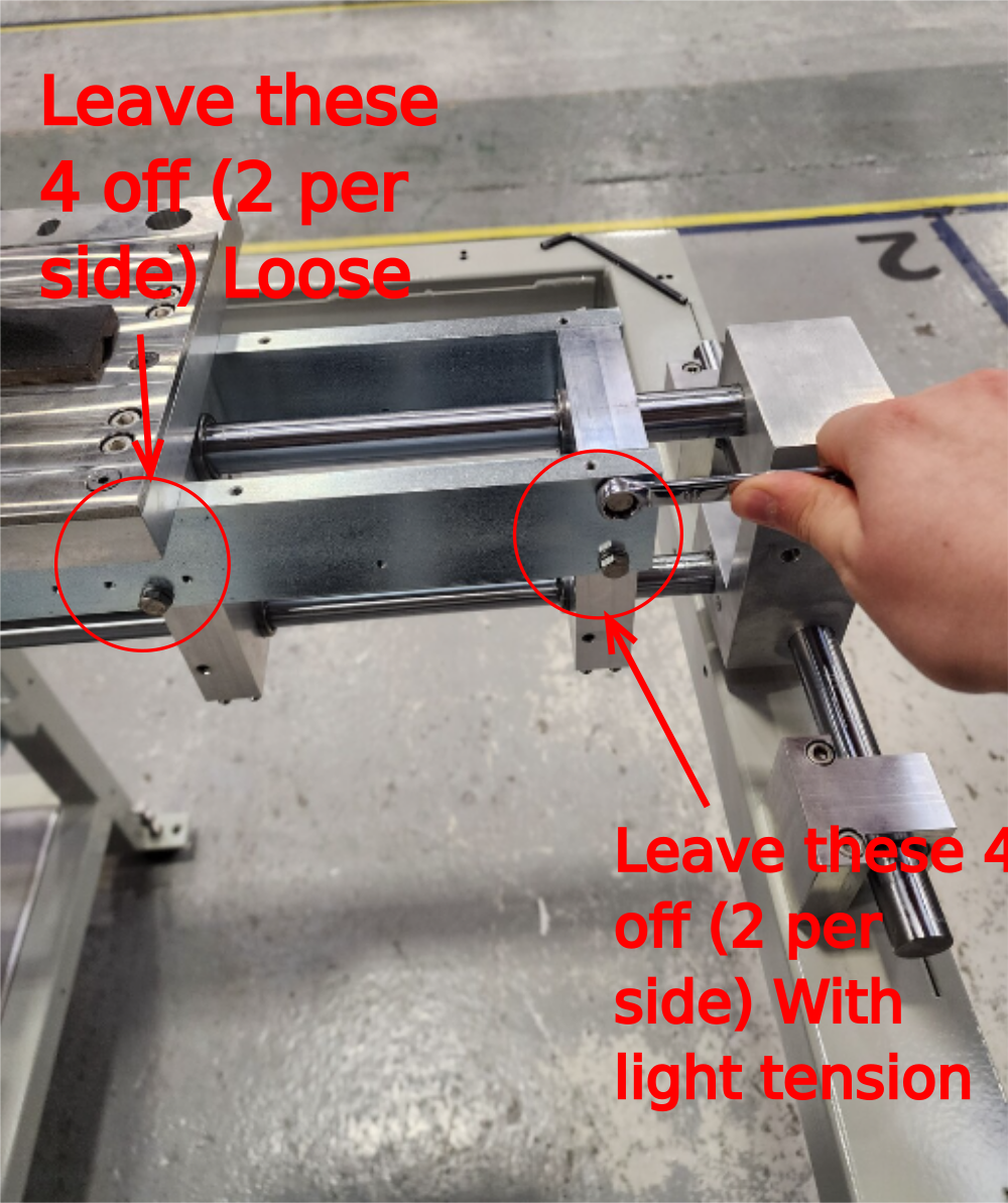
3 Check X axis level . To adjust, side bars require positioning. Adjust as shown to set level.
- Apply light pressure to set bolts indicated.
- Leave indicated set bolts loose
- Adjust up or down to adjust X axis table level
- Apply final tension to set bolts and recheck level (do not apply adhesive yet )

Étape 4 - Set flatness
PICTURES REQUIRED OF THESE STEPS PLEASE
Height position between tables now needs to be checked and set if required
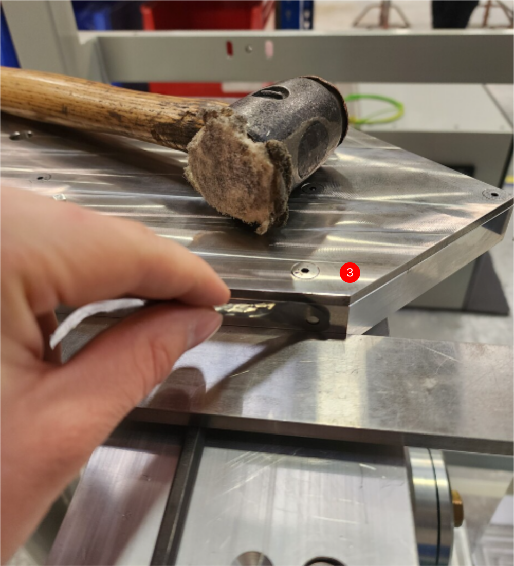
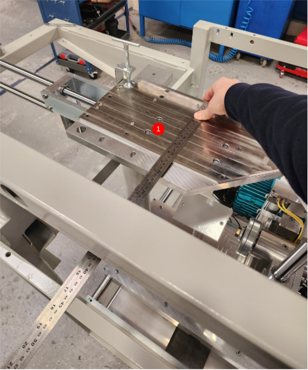
1 Use 1 meter straight edge across both tables as shown, use feeler gauges to identify height difference between tables
2 Add full face shim to table identified as low, ensuring original shims are kept in place
3 Recheck levels once shim is added
4 Use straight edge and feeler gauges to check flatness . Eject table may be adjusted slightly (-+ 1 level division) to aid alignment
5 Check transition between tables is smooth, using the engineers level to gauge

Étape 5 - Set front alignment
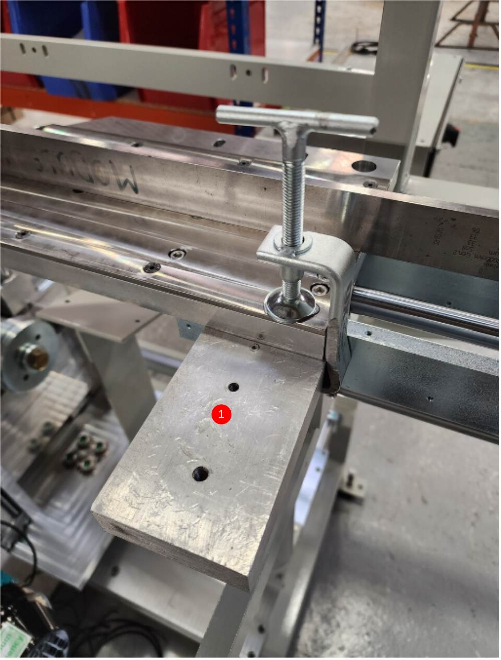
1 Use small clam[p and block as shown to hold 1 meter straight edge against edges of cut tables2 With light pressure on the
6 off M6 socket caps on eject table
4 off M8 socket caps on the fixed table
Adjust the points int he direction shown to achieve alignment on the straight edge
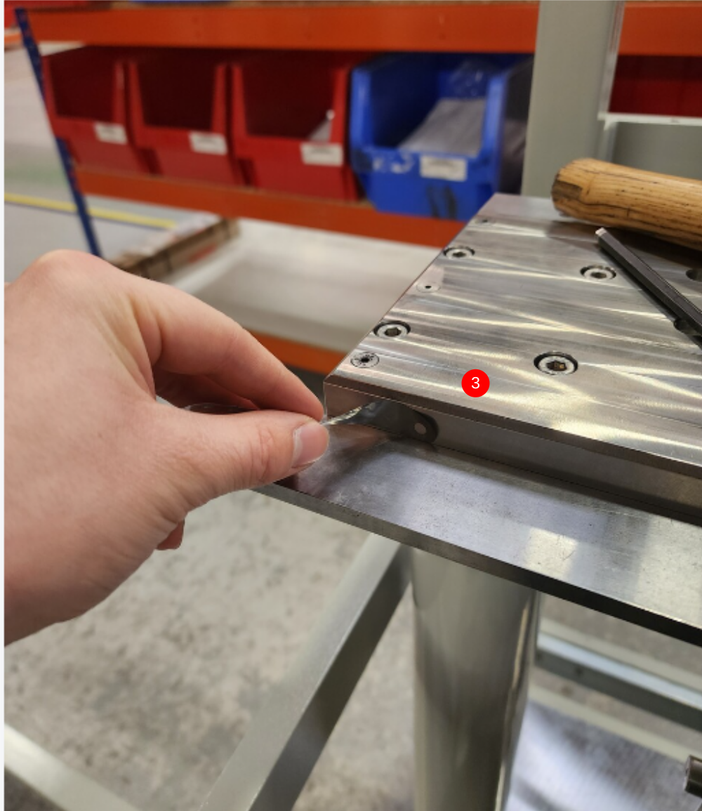
3 Check alignment is correct using 0.002 feeler gauge to check faces of cut tables to straight edge
Étape 6 - Check parallel
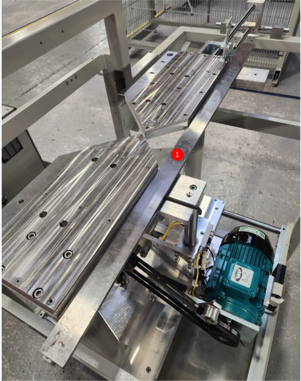
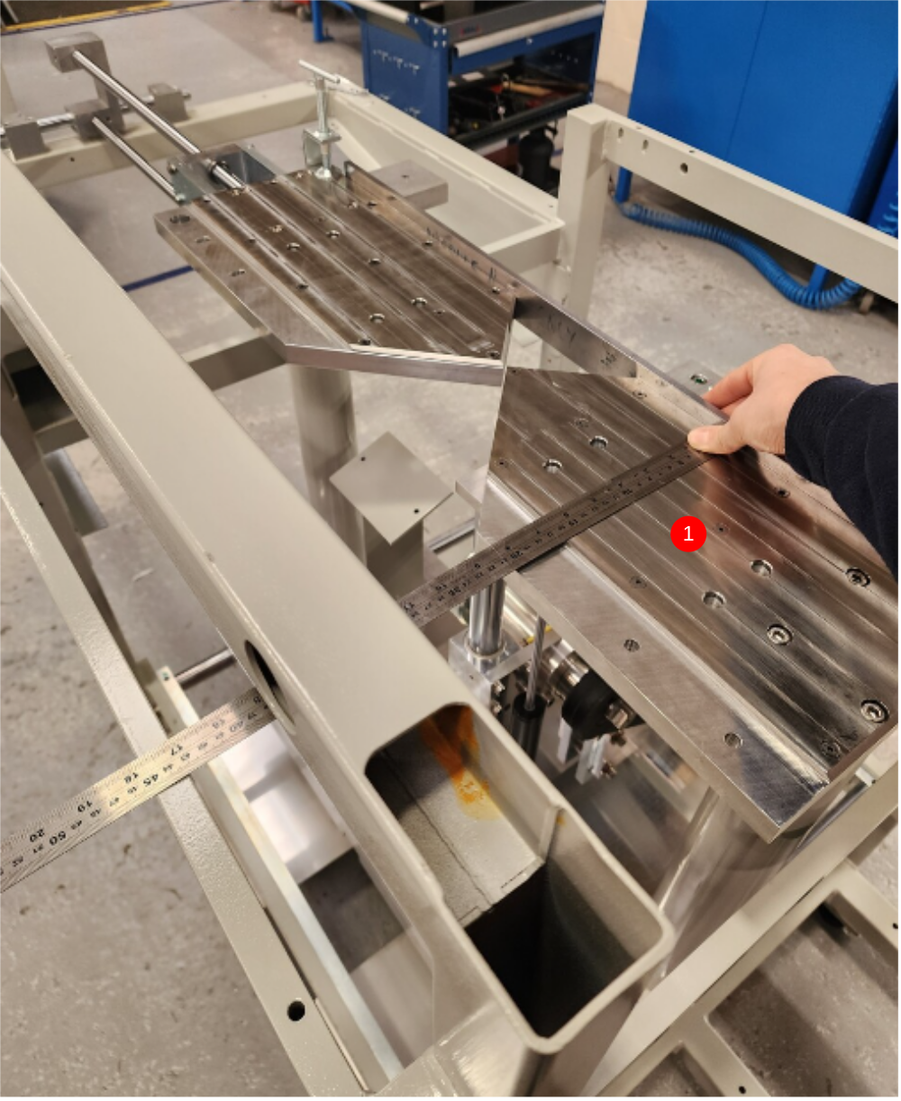
1 Use Steel rule to measure from pads to rear fence mount on frame from both tables as shown
2 Measurement neds to be the same (+- 1mm)
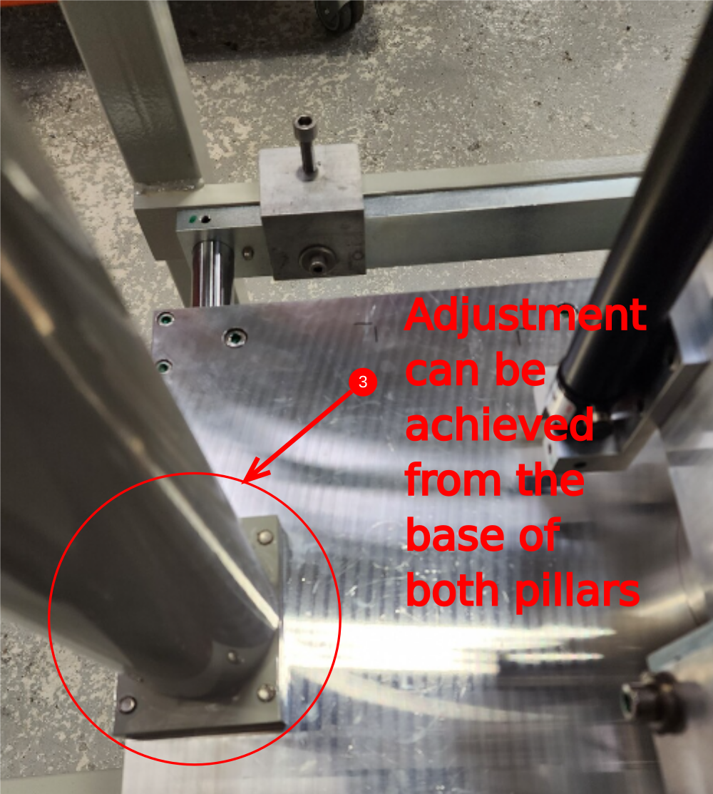
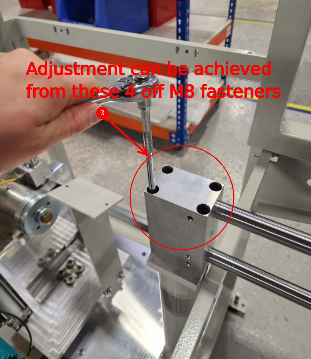
3 Use adjustment in pads, and pillar supports to correct
4 Ensure front alignment of tables is checked after adjusting. Ensure alignment and parallel are both met
Étape 7 - Finalise fasteners
Finalise all fasteners in the order as shown
Étape 8 - Quality check
All cut table settings to be checked and signed off by supervisor

Étape 9 - Fit eject cylinder
fit eject cylinder with spacer
Ensure alignment
Ensure correct position of cylinder thread adjustment

Étape 10 - Fit Cylinder fittings
fit flow regs with one off extension

Étape 11 - Fit energy chain
Fit energy chain with backing plate.
Ensure pivoting bracket is fitted to correct end

Étape 12 - Fit cover fixing bar
Fit cover fixing bar with 2 off spacers and M8 sockets
Tap holes to clean m5 threads

Étape 13 - Fit gap covers
Fit 2 off gap covers with m5 socket caps
do not finalise position S

Étape 14 - Fit ejector cover

Étape 15 - Set flatness
Use infeed pad as datum
Use 1 meter straight edge and feeler gauges
Adjust eject table to suit infeed pad
Étape 16 - Set front alignment
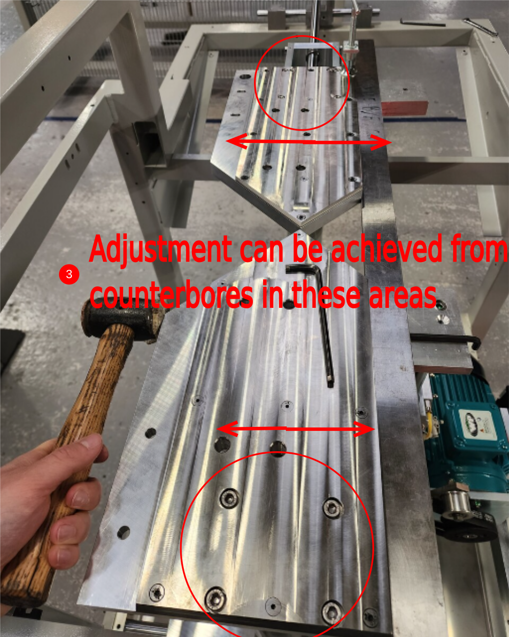
Set front alignment using adjustment in counter bores in pads
Use 1 meter straight edge and feeler gauges to set
Étape 17 - Check parallel
Use Steel rule to measure from pads to rear fence mount on frame from both tables
This measurement needs to be the same
Use adjustment in pads, and pillar supports to correct
Ensure front alignment of tables is held when adjusting
Étape 18 - Finalise fasteners
Finalise all fasteners with 243 and correct tension once adjustments are complete
Étape 19 - Fit eject cylinder
fit eject cylinder with spacer
Ensure alignment
Ensure correct position of cylinder thread adjustment
Étape 20 - Fit Cylinder fittings
fit flow regs with one off extension
Étape 21 - Fit energy chain
Fit energy chain with backing plate.
Ensure pivoting bracket is fitted to correct end
Étape 22 - Fit cover fixing bar
Fit cover fixing bar with 2 off spacers and M8 sockets
Tap holes to clean m5 threads
Étape 23 - Fit gap covers
Fit 2 off gap covers with m5 socket caps
do not finalise position S
Étape 24 - Fit ejector cover
Étape 25 - Fit ejector cover
Étape 26 - Quality Check
Both cut tables should be inspected for flatness before commencing fitting
Use 1 meter straight edge and 0.002" 0.05mm feeler gauge to inspect
Report any deviation above Feeler gauge size


Draft
 Français
 English
 Deutsch
 Español
 Italiano
 Português