bench assembly instructions for main rotary base of saw

Difficulté
Difficile
Durée
0 heure(s)
Sommaire
- 1 Introduction
- 2 Étape 1 - Unless otherwise stated
- 3 Étape 2 - Prepare components
- 4 Étape 3 - Fit hard stop
- 5 Étape 4 - Fit bearing cage and turntable plate
- 6 Étape 5 - Assemble base
- 7 Étape 6 - Fit turntable to base
- 8 Étape 7 - Fit Servo motor
- 9 Étape 8 - Fit D0015663 SR Axis Motor Guard
- 10 Étape 9 - Fit mounting brackets
- 11 Commentaires
Introduction
Tools Required
Standard hex key set
Standard spanner set
Heat gun
Large Internal Circlip pliers
Standard circlip pliers
8mm hand reamer
Grease gun
Torque wrench
Parts Required
B0000028 Thrust Bearing 140 I/D 180 O/D 31 Long (FAG) x 1
B0000032 Linear Bearing: Ø30 x 50 Compact (Metal Case Only) x 4
B0001087 Angular Contact Bearing 70 I/D 125 O/D 24 Long x 1
B0001088 Circlip 125mm Internal x 1
C0001122K Servo Motor: Beckhoff AM8032-1E10 (Keyed) x 1
C0001179-100 Gearbox NPTO 100-1 x 1
D0004019E Turntable Mk5 (5334E) x 1
D0004033E Alignment Disc Mk5 x 1
D0004147E Turntable Shaft Mk5 x 1
D0004320E Thrust Bearing Housing Mk5 x 1
D0004336 Stay Bar x 2
D0004514E Turntable Base Mk5 x 1
D0004516 Front Bearing Block (5294) x 2
D0010778 Turntable Stop Arm x 1
D0010796 Turntable Housing Cover x 1
H0004631 Shaft 30mm: Base Slide x 2
M0001176 M6 Stainless lock washer x 4
D0015663 SR Axis Motor Guard x 1Étape 1 - Unless otherwise stated
All bolts to have Loctite 243 adhesive applied unless otherwise stated
All Threaded Pneumatic connections to have Loctite 570 applied
All bolts to be pen marked once adhesive applied and correct tension added

Étape 2 - Prepare components
1 Use 8mm hand reamer to clean holes indicated in D0004033E Alignment Disc Mk5
2 Attach smaller bearing outer cage to disc using press
3 Use 8mm hand reamer to clean indicated holes on D0004019E Turntable Mk5 (5334E)


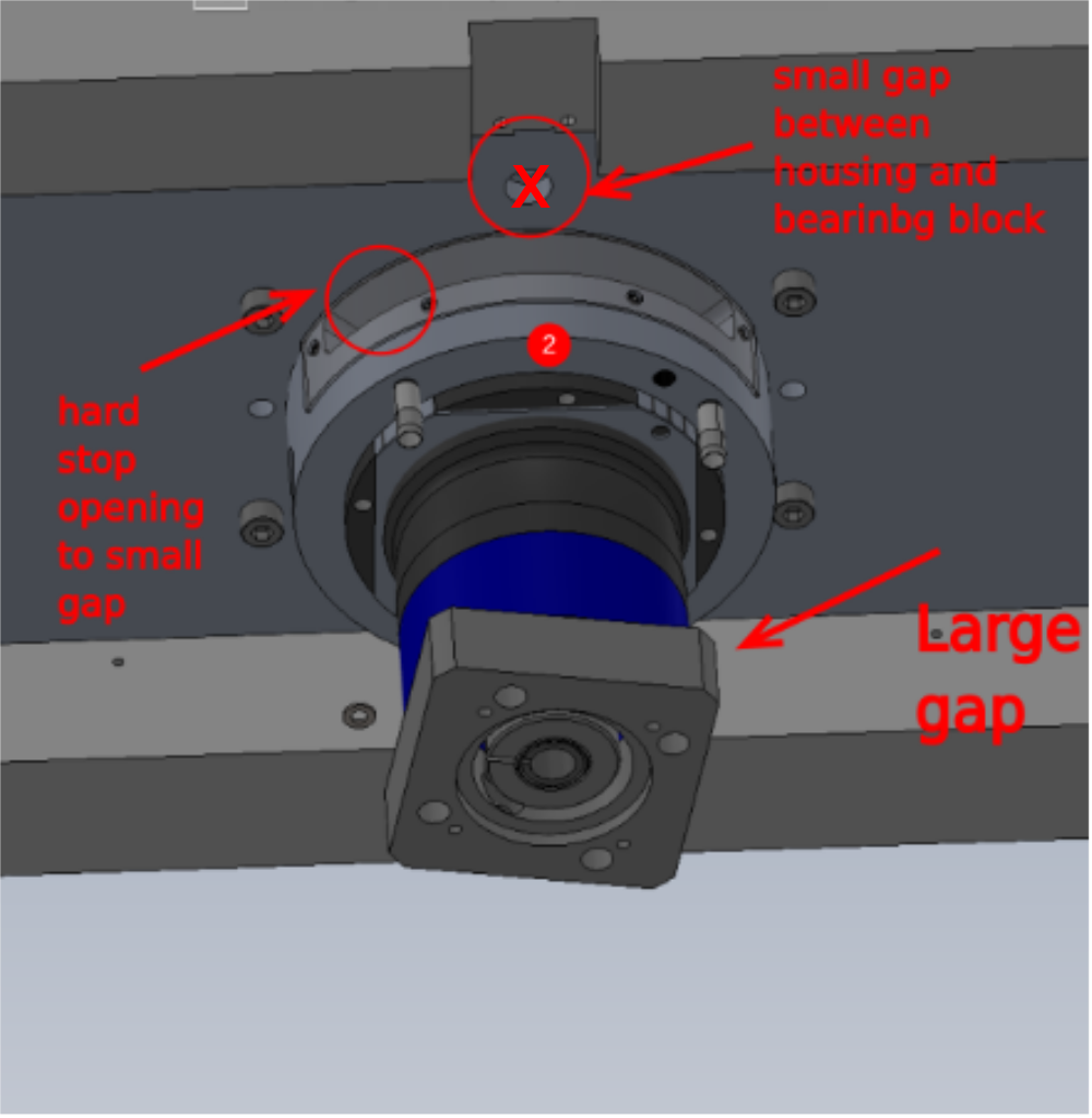
Étape 3 - Fit hard stop
1 Fit 2 off 5mm x 28mm dowels to D0010778 Turntable Stop Arm Use Loctite 270 to secure
2 Cut down dowels to 6mm protrusion
3 Fit to flat on turntable pin and secure with 4 off M10 x 50 socket caps


Étape 4 - Fit bearing cage and turntable plate
1 Fit bearing cage from B0000028 Thrust Bearing 140 I/D 180 O/D 31 Long (FAG), Apply more grease then position assembly shown on top and visually align 8mm reamed holes
2 Position D0004019E Turntable Mk5 as shown. Ensure hard stop is in centre position
All 8mm reamed holes should align through the 3 parts. Turntable shaft, alignment disc and turntable
3 Add 2 off m4 x 20 socket caps and tension lightly to indicated holes to fix together
4 Insert 4 off 8mm x 50mm hardened dowels to fix all three parts in correct alignment
5 Remove 2 off previously fitted M4 socket caps, apply adhesive and apply final tension
6 Add 4 off m14 x 60 socket caps and A form washers to finalise fixing of turntable plate
Check rotation once assembled . Movement should be smooooooth and consistent


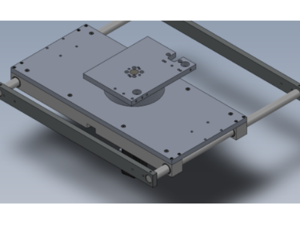
Étape 5 - Assemble base
1 Fit 4 off B0000032 Linear Bearing: Ø30 x 50 Compact bearings to D0004516 Front Bearing Block (5294) x 2 as shown , ensure bearings are greased after fitting
2 Attach D0004514E Turntable Base Mk5 as shown . Use M6 x 25 and M8 x 25socket caps to fix . Ensure all external faces are flush with bearing blocks
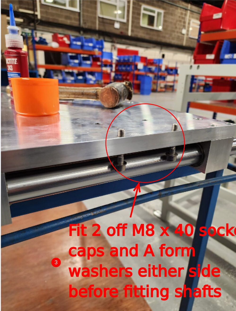
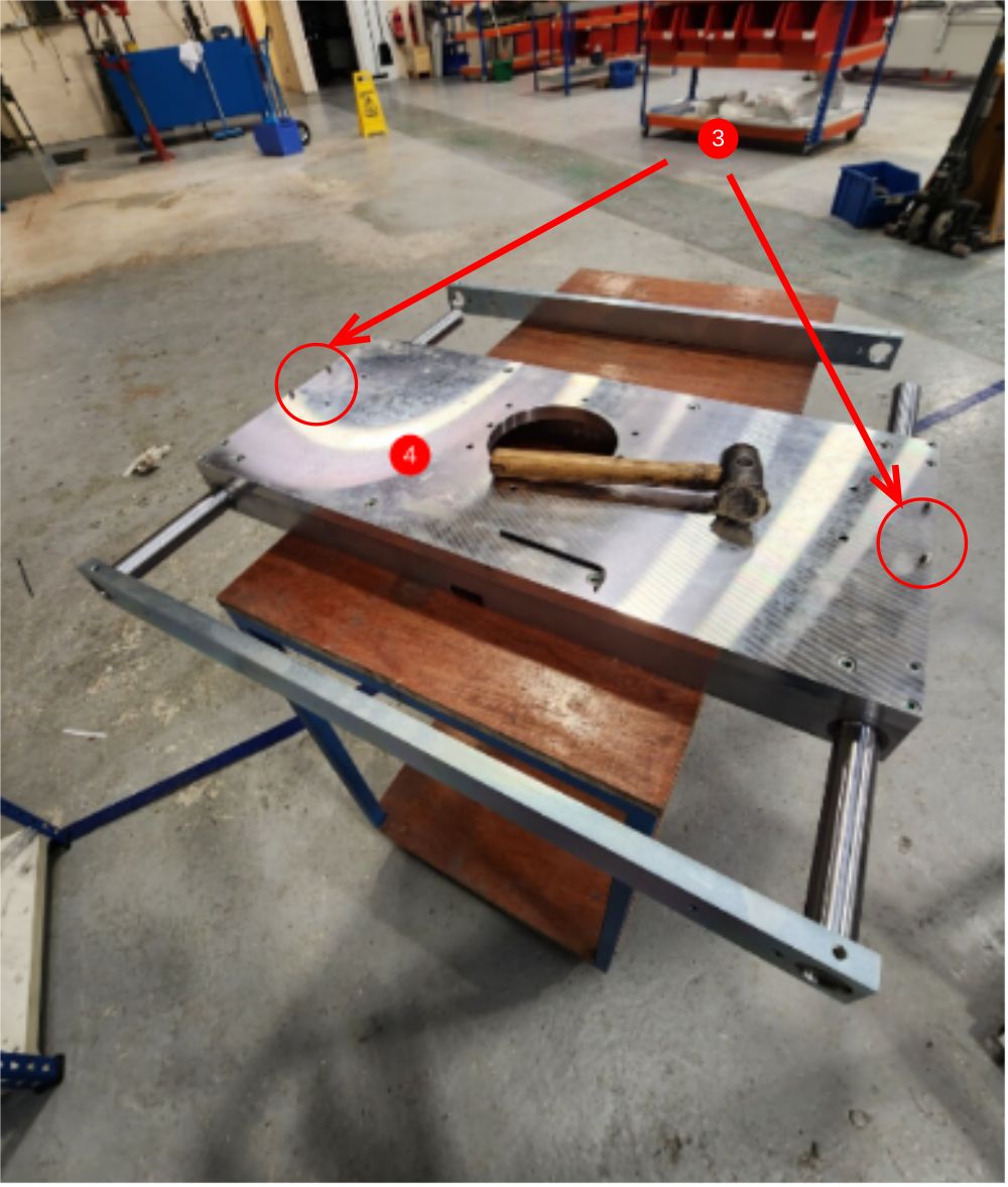
3 Clean 2 off H0004631 Shaft 30mm, Fit 4 off M8 x 40 socket caps and A form washers to indicated holes . Insert through bearing blocks . Ensure dimple in shaft is at the indicated end
4 Fit D0004336 Stay Bar x 2 as shown. Use M8 x 12 kcp grubscrews to locate onto shaft dimple. End of shaft with no dimple, set staybar flush with shaft and tighten grubscrew onto shaft
If the stay bars are a tight fit, these will require polishing with emery tape to remove debris from coating process . Ensure gradually polishing of bores to ensure bores are taken oversize
5 Check and finalised all fixings


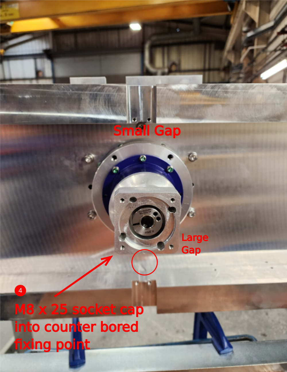
Étape 6 - Fit turntable to base
1 Mount Built base as shown, using clamps and spacer blocks. This is a two person lift . Ensure clamps are fitted as shown to allow fitment of brackets later on
2 Insert built turntable, orientated as shown.
3 Fit D0010796 Turntable Housing Cover using m4 x 6 button sockets 6. Housing can be rotated for easier access when fitting cover
4 Fix with 5off M8 x 35 socket caps and A form washers and 1 off M8 x 25 socket cap with no washer

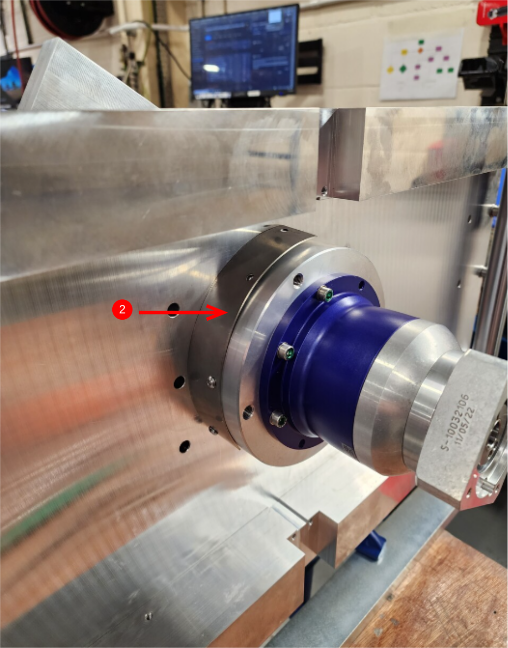

Étape 7 - Fit Servo motor
1 Remove key and Degrease thoroughly spindle on C0001122K Servo Motor: Beckhoff AM8032-1E10 (Keyed)
2 Insert motor into gearbox and orientated servo plug as indicated
Affix motor to gearbox using M5 socket caps (size required)
3 Tension friction coupling to 9.5nm using torque wrench , then insert gearbox bung . Write torque setting on indicated face


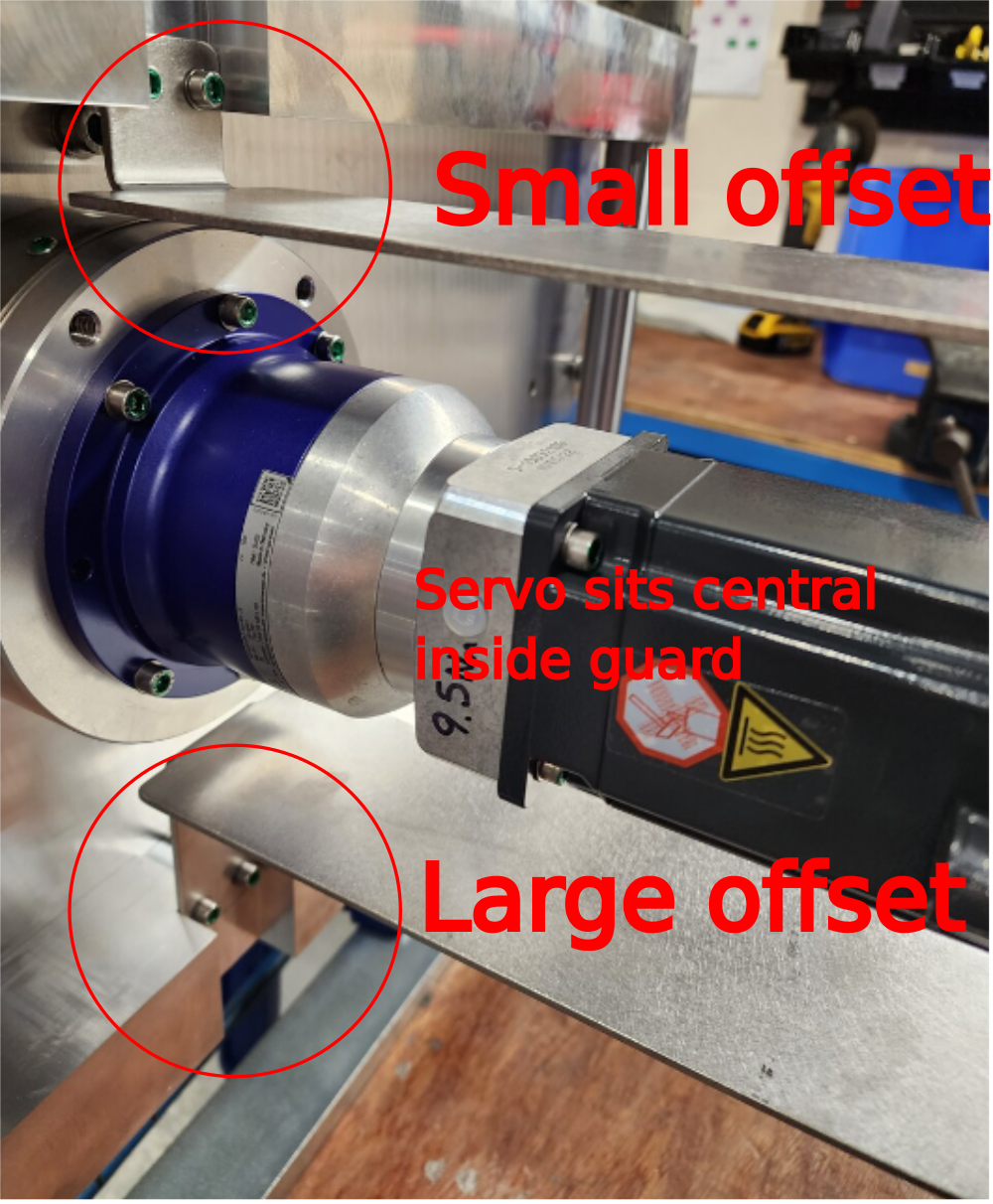
Étape 8 - Fit D0015663 SR Axis Motor Guard
Fit D0015663 SR Axis Motor Guard as shown . Use M5 x 16 socket caps and a form washers to fix .
Note correct orientation of offset of part

Étape 9 - Fit mounting brackets
Fit 4 off mounting brackets for later installation to main saw frame
Details of fasteners required please


Draft
 Français
 English
 Deutsch
 Español
 Italiano
 Português