| [version en cours de rédaction] | [version en cours de rédaction] |
| Ligne 14 : | Ligne 14 : | ||
|Step_Title=<translate>Infeed to Machining Centre</translate> | |Step_Title=<translate>Infeed to Machining Centre</translate> | ||
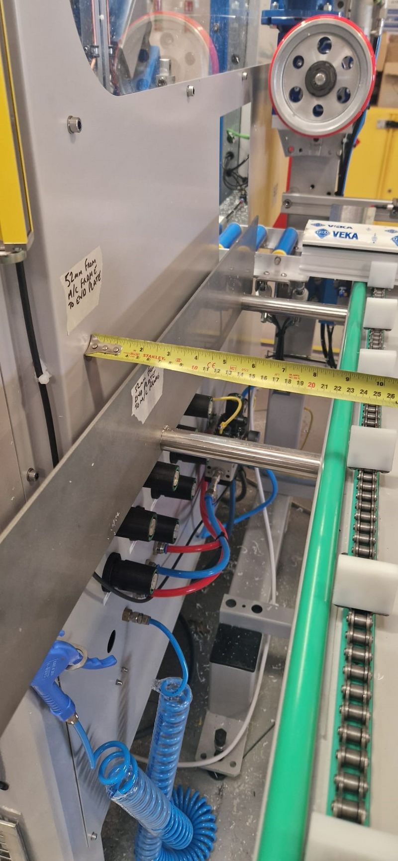
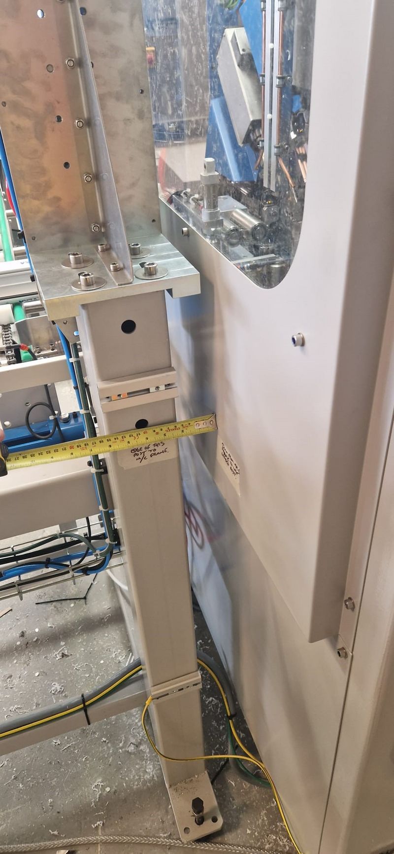
|Step_Content=<translate>Measure and mark up the distance between two points (one on each) of the two modules. Mark up the points in a place where it is easy to read the markings and simply practical to get the two modules in a similar position (gap between the two) on installation - preferably on the front and the back of the modules. This makes it easier and closer to adjusting the loadpos and datum on the x-axis once setting up accuracy.</translate> | |Step_Content=<translate>Measure and mark up the distance between two points (one on each) of the two modules. Mark up the points in a place where it is easy to read the markings and simply practical to get the two modules in a similar position (gap between the two) on installation - preferably on the front and the back of the modules. This makes it easier and closer to adjusting the loadpos and datum on the x-axis once setting up accuracy.</translate> | ||
| + | |Step_Picture_00=Install_markings_and_measurements_ZX5_INF.jpg | ||
| + | |Step_Picture_01=Install_markings_and_measurements_ZX5_INF2.jpg | ||
}} | }} | ||
{{Tuto Step | {{Tuto Step | ||
|Step_Title=<translate>Machining Centre to Outfeed</translate> | |Step_Title=<translate>Machining Centre to Outfeed</translate> | ||
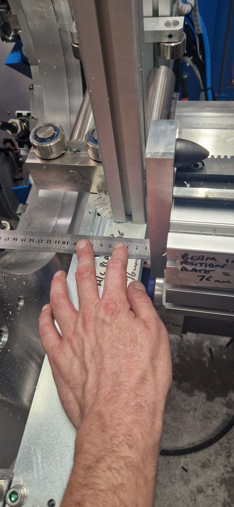
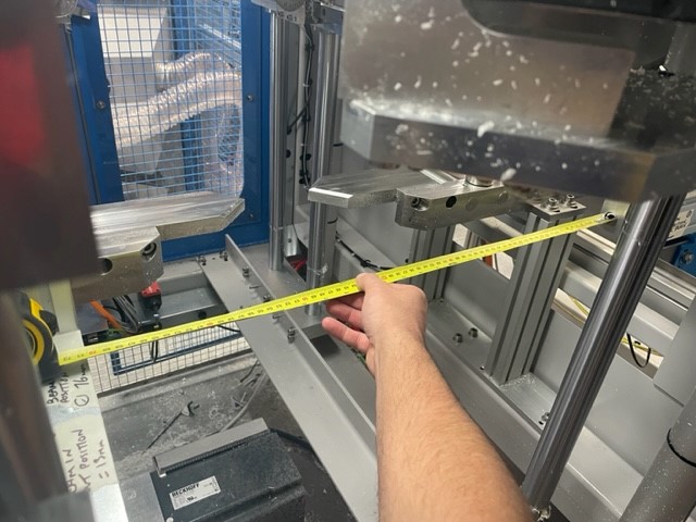
|Step_Content=<translate>Measure and mark up two points between the MACHINING CENTRE and the X-AXIS BEAM. Do this with the beam in the HOME position and also the OUT position. This gives the installation engineer the option of two different methods to go off, whichever suits them and to also check the measurements with the beam in both positions. This makes it easier for the installation engineer to get these two points as close as possible to where they were at Stuga base resulting in little - no adjustments to the X-axis drive min/max and datum. positions.</translate> | |Step_Content=<translate>Measure and mark up two points between the MACHINING CENTRE and the X-AXIS BEAM. Do this with the beam in the HOME position and also the OUT position. This gives the installation engineer the option of two different methods to go off, whichever suits them and to also check the measurements with the beam in both positions. This makes it easier for the installation engineer to get these two points as close as possible to where they were at Stuga base resulting in little - no adjustments to the X-axis drive min/max and datum. positions.</translate> | ||
| + | |Step_Picture_00=Install_markings_and_measurements_ZX5_Beam.jpg | ||
| + | |Step_Picture_01=Install_markings_and_measurements_ZX5_1.jpg | ||
}} | }} | ||
{{Tuto Step | {{Tuto Step | ||
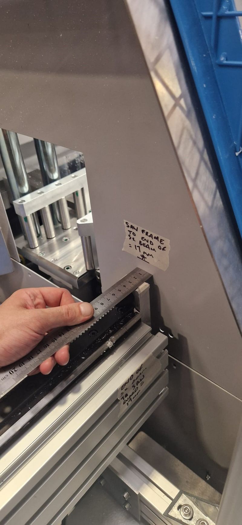
|Step_Title=<translate>Saw Infeed to Saw</translate> | |Step_Title=<translate>Saw Infeed to Saw</translate> | ||
|Step_Content=<translate>Measure and mark up the distance between the SX-AXIS BEAM to the SAW (guard). This makes it easier for the installation engineer to get these two points as close as possible to where they were at Stuga base resulting in little-no adjustments to the SX-axis drive min/max and datum positions.</translate> | |Step_Content=<translate>Measure and mark up the distance between the SX-AXIS BEAM to the SAW (guard). This makes it easier for the installation engineer to get these two points as close as possible to where they were at Stuga base resulting in little-no adjustments to the SX-axis drive min/max and datum positions.</translate> | ||
| + | |Step_Picture_00=Install_markings_and_measurements_ZX5_saw.jpg | ||
}} | }} | ||
{{Tuto Step | {{Tuto Step | ||
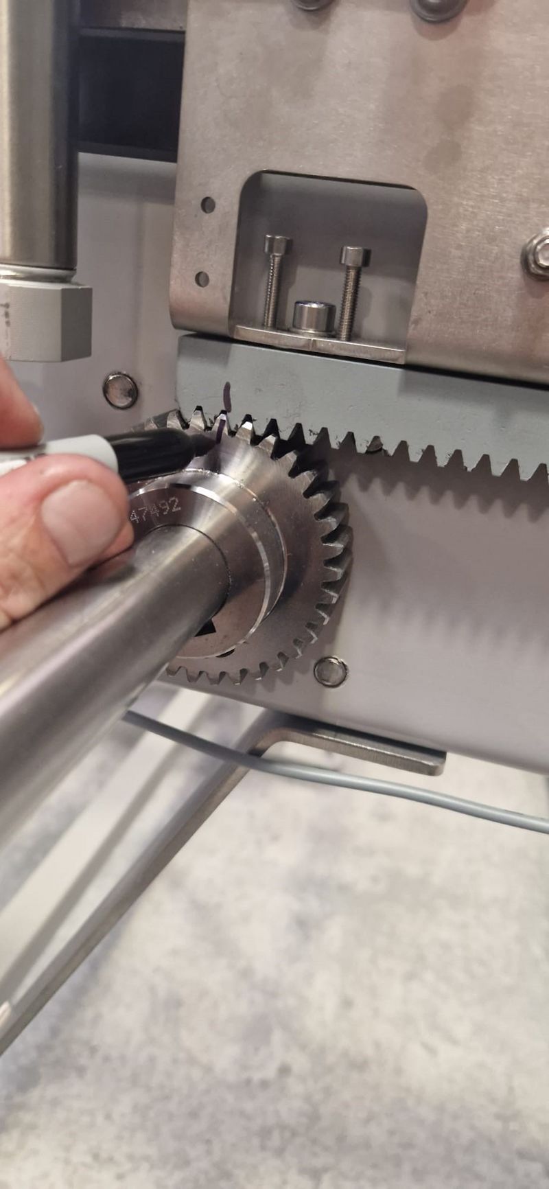
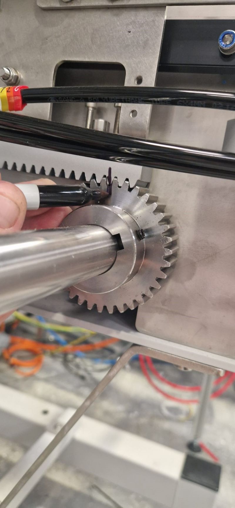
|Step_Title=<translate>Racks and Pinion Gears</translate> | |Step_Title=<translate>Racks and Pinion Gears</translate> | ||
|Step_Content=<translate>Draw a line between every RACK and PINION GEAR on all the cranks (C,D & E). This helps the installation engineer, and even the customer, to line up and mesh the cranks quickly and easily should these become unmeshed.</translate> | |Step_Content=<translate>Draw a line between every RACK and PINION GEAR on all the cranks (C,D & E). This helps the installation engineer, and even the customer, to line up and mesh the cranks quickly and easily should these become unmeshed.</translate> | ||
| + | |Step_Picture_00=Install_markings_and_measurements_ZX5_gears.jpg | ||
| + | |Step_Picture_01=Install_markings_and_measurements_ZX5_gears1.jpg | ||
}} | }} | ||
{{Tuto Step | {{Tuto Step | ||
| Ligne 36 : | Ligne 43 : | ||
Also it is VERY important that the transfer beams have a cap head bolt (M5 x 30) put through the rack plates and transfer beams before they are detached from the arms to keep the transfer racks and pinion gears meshed in the correct position during transit and when arriving at the customers.</translate> | Also it is VERY important that the transfer beams have a cap head bolt (M5 x 30) put through the rack plates and transfer beams before they are detached from the arms to keep the transfer racks and pinion gears meshed in the correct position during transit and when arriving at the customers.</translate> | ||
| + | |Step_Picture_00=Install_markings_and_measurements_ZX5_Trans.jpg | ||
}} | }} | ||
{{Tuto Step | {{Tuto Step | ||
Version actuelle datée du 18 juillet 2023 à 11:40
Markings and measurements required by the Install team, after a machine commission. This helps towards a smoother install process, getting the machine module positions and fencing to be in the same place (or close to) as they were during the commission at stuga base.
Sommaire
Étape 1 - Infeed to Machining Centre
Measure and mark up the distance between two points (one on each) of the two modules. Mark up the points in a place where it is easy to read the markings and simply practical to get the two modules in a similar position (gap between the two) on installation - preferably on the front and the back of the modules. This makes it easier and closer to adjusting the loadpos and datum on the x-axis once setting up accuracy.
Étape 2 - Machining Centre to Outfeed
Measure and mark up two points between the MACHINING CENTRE and the X-AXIS BEAM. Do this with the beam in the HOME position and also the OUT position. This gives the installation engineer the option of two different methods to go off, whichever suits them and to also check the measurements with the beam in both positions. This makes it easier for the installation engineer to get these two points as close as possible to where they were at Stuga base resulting in little - no adjustments to the X-axis drive min/max and datum. positions.
Étape 3 - Saw Infeed to Saw
Measure and mark up the distance between the SX-AXIS BEAM to the SAW (guard). This makes it easier for the installation engineer to get these two points as close as possible to where they were at Stuga base resulting in little-no adjustments to the SX-axis drive min/max and datum positions.
Étape 4 - Racks and Pinion Gears
Draw a line between every RACK and PINION GEAR on all the cranks (C,D & E). This helps the installation engineer, and even the customer, to line up and mesh the cranks quickly and easily should these become unmeshed.
Étape 5 - Guarding
Mark up any guarding that is likely to be detached on strip down so the engineer on installation can easily locate and attach to the machine.
Étape 6 - Transfer Beams
Mark up the transfer beams from numbers 1-9 (1 being closest to the Saw & M/C end and 9 being closest to the extraction end) using the number stickers provided in the workshop.
Also it is VERY important that the transfer beams have a cap head bolt (M5 x 30) put through the rack plates and transfer beams before they are detached from the arms to keep the transfer racks and pinion gears meshed in the correct position during transit and when arriving at the customers.
Étape 7 - Fence Panels and Posts
Mark up, in some sort of order, all FENCE PANELS and POSTS. This will save time in ordering and attaching the guarding for the engineer on site .
Étape 8 - Detached Parts
Mark up any parts which are set in position that will be detached from the machine.
Such as;
- Light Curtain
- OBeam Sensor and Reflector
- Buffer Beams and Joining Plates
- Gate/Fence Posts
- Outfeed Profile Support Plate
- Deflector Plate by the Saw
- Support Posts for Arms on modules C & E
Étape 9 - Spare Fixings
Any fixings/fasteners - such as bolts, nylocs, grubscrews, t-nuts etc - that are removed on stripdown should be put back where they were removed from and tightened into place. This helps on installation with the correct bolts being there and ready to use. Also, place in a bag and send out identical fixings and fasteners that are removed so there is spares on installation should any be vacant or lost during transit.
Some examples of these are;
- Transfer Beam - Button heads (M8 x 16)
- E-Stop - Cap Heads (M4 x 12)
- Fence Panels - Cap Heads (M6 x 35)
- Saw Outfeed Tray - Cap Heads (M6 x 16)
- Maytec Chamber Fixings - Cap Heads (m8 x 16 & 20 w/ penny / thick washers), M4, M5, M6 & M8 T-Nuts,
Draft
 Français
 English
 Deutsch
 Español
 Italiano
 Português