How to convert a TwinCAT2 project on an older Autoflow to TwinCAT3. This needs to be done when updating to Windows 10

Difficulté
Difficile
Durée
2 heure(s)
Sommaire
- 1 Introduction
- 2 Étape 1 - Get connected to the Camera PC of the machine to be updated
- 3 Étape 2 - Get a backup of the original TSM file
- 4 Étape 3 - Get copy of current PLC and Reset project
- 5 Étape 4 - Convert the TC2 project to TC3
- 6 Étape 5 - Create the clone to pull the latest tc3Multi and PLC_Reset
- 7 Étape 6 - Replace the old PLC code with the version control latest
- 8 Étape 7 - Connect to the Beckhoff Backend PC
- 9 Étape 8 - Update the EtherCAT Device Adaptor
- 10 Étape 9 - Add the IO Links
- 11 Étape 10 - Change the inverterGoFwd links
- 12 Étape 11 - Copy the Axis Links
- 13 Étape 12 - Remove the "Interpolate" Axis group
- 14 Étape 13 - Change V and W axis PLC links
- 15 Étape 14 - Add the reset link
- 16 Étape 15 - Ensure the front end has the latest software versions
- 17 Étape 16 - Update the front end parameters
- 18 Étape 17 - Update the Control Systems log
- 19 Commentaires
Introduction
The Beckhoff system provides a system for upgrading to TC3 from a TC2 project. This tutorial goes through the steps required to ensure the links and setup of the original TC2 project are copied through to TC3.
Étape 1 - Get connected to the Camera PC of the machine to be updated
You will need to get a backup of the TC2 project from this machine, and use it to set up all the correct IO links in the TC3 project
Étape 2 - Get a backup of the original TSM file
- Dial in to Camera / VM PC
- Open System manager
- File->Save As
- Rename it to [build number].[todays date]
- Copy to c:\twinCAT\stuga\ on the "New" camera PC


Étape 3 - Get copy of current PLC and Reset project
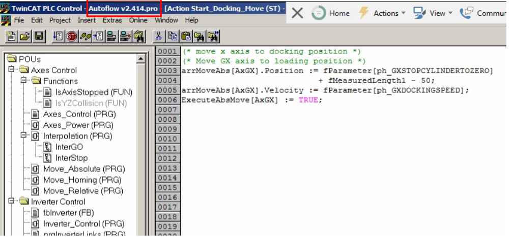
- Open the PLC Control program on the camera PC
- Note the version of software currently running (.pro)
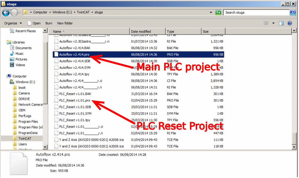
- Find the .pro file in c:\TwinCAT\Stuga\
- Copy to c:\twinCAT\stuga\ on the "New" camera PC
- Also copy the latest PLC Reset project
Étape 4 - Convert the TC2 project to TC3
- Open Visual Studio
- Create a new TC3 project called [BuildNo] in c:\TwinCAT\Stuga\
- Make sure "Create Directory..." is Unticked
- Right Click on the project name and select ‘Load Project from TwinCAT 2.11 Version…’
- Click Cancel on the two windows asking to convert the PLC project
- Ignore or cancel any warnings about libraries (this part will be replaced later)

Étape 5 - Create the clone to pull the latest tc3Multi and PLC_Reset
- Create the clone in c:\TwinCAT\[BuildNo]\Source
- If an error is produced after cloning, just use the "Add" function to add the clone
Étape 6 - Replace the old PLC code with the version control latest
- Delete the old PLC projects
- using Add existing item, add the tc3Multi then PLC_Reset projects from c:\TwinCAT\[BuildNo]\Source.
- Ensure Use Original project Location is selected
- Build the solution to create the instances ready for linking
- Ensure the Port numbers are correct (851=tc3Multi, 852=PLC_Project)
Étape 7 - Connect to the Beckhoff Backend PC
Add a new route
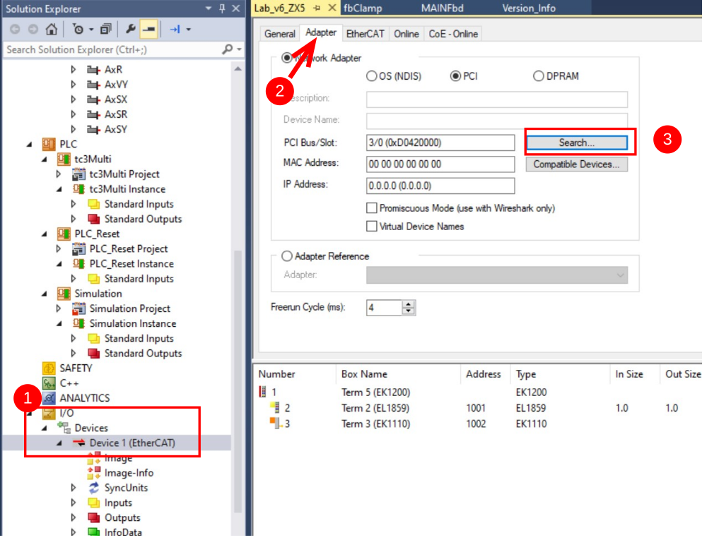
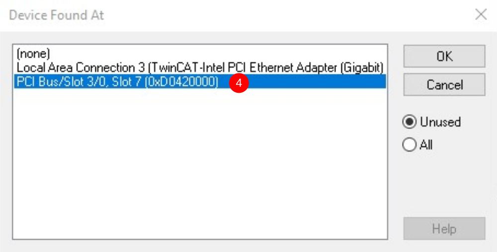
Étape 8 - Update the EtherCAT Device Adaptor
Navigate to the Adaptor settings and search for the correct one on the new Beckhoff PC
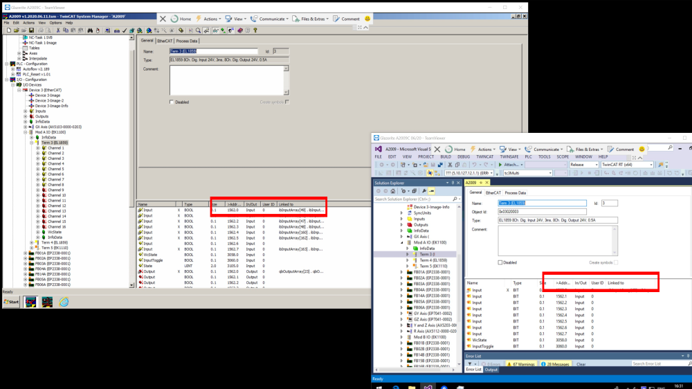
Étape 9 - Add the IO Links
Using System Manager on the Camera PC, create new copies of all the links on all devices from the System Manager to the new project.
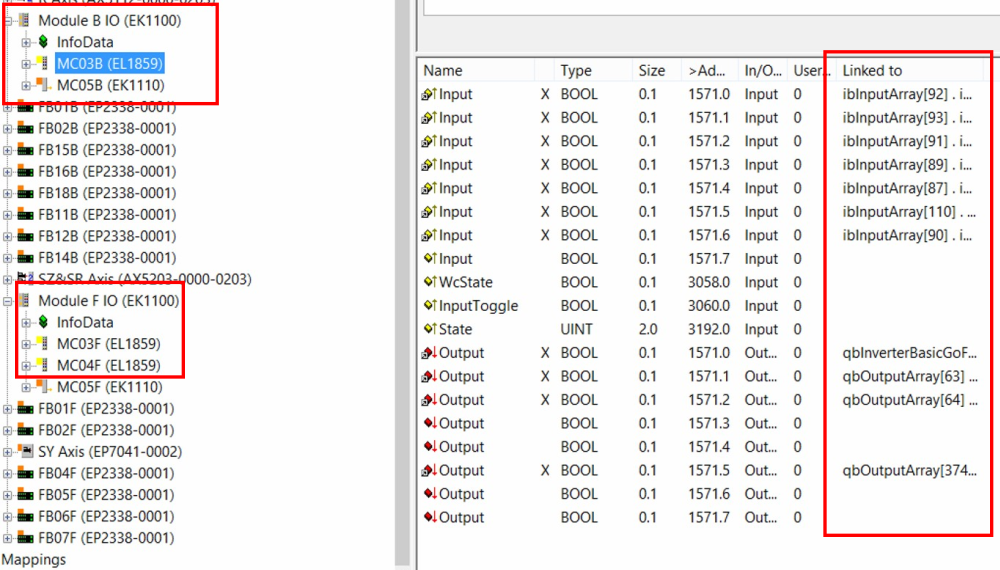
Étape 10 - Change the inverterGoFwd links
TC2 software used a system of inverter objects to control the spindles, saw blade and extractor. The mapping will show InverterGoFwd mapping.
These need to be changed to the correct output numbers for the outputs in question.
On an Autoflow, these are
Slice MC03B (ModuleB)
Ch0 - Y62 Spindle Inverter
Slice MC2F (module F)
Ch1 - Y97 Saw Blade
Ch 2 - Y98 Extractor
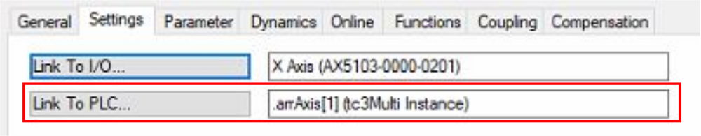
Étape 11 - Copy the Axis Links
The PLC links will be missing - reinstate them as per System Manager on old Camera PC
If The 'Link to PLC' field is not viewable on Twincat 2 project use the below guide for the correct links required:
Étape 12 - Remove the "Interpolate" Axis group
Right click and select delete

Étape 13 - Change V and W axis PLC links
When converting for a ZX4 machine, the V and W axis links will need to be changed
V = arrAxis[11]
W = arrAxis[12]
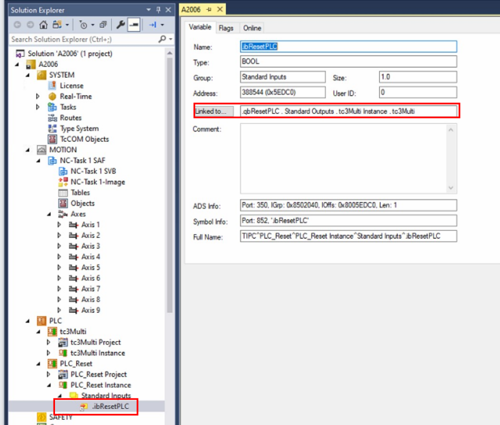
Étape 14 - Add the reset link
Set a link from ibResetPLC on PLC_Reset to qbResetPLC on tc3Multi
Étape 15 - Ensure the front end has the latest software versions
Étape 16 - Update the front end parameters
In params.saw, the following parameters must be updated
controllerType=5
amsnetId= [AmsNetId of the new Beckhoff PC]
twinCAT Address=[AmsNetId of the new Beckhoff PC]
AllWasteAtStart=1
useSawForYNotch=1
Étape 17 - Update the Control Systems log
Update
- Front End PC and OS
- Back End PC and OS
- Software versions
Draft
 Français
 English
 Deutsch
 Español
 Italiano
 Português