Bench assembly instructions for z axis components
Sommaire
- 1 Introduction
- 2 Étape 1 - Unless otherwise stated
- 3 Étape 2 - Clean Threads
- 4 Étape 3 - Assemble support cylinder 1
- 5 Étape 4 - Assemble support cylinder 2
- 6 Étape 5 - Assemble tensioners
- 7 Étape 6 - Check fit of D0001926
- 8 Étape 7 - Fit bearing
- 9 Étape 8 - Tension drive coupling
- 10 Étape 9 - Finalise drive coupling
- 11 Étape 10 - Finalise idler coupling
- 12 Étape 11 - Check fit of leadscrew to coupling
- 13 Étape 12 - Check bearing fit
- 14 Commentaires
Introduction
Tools Required
Standard hex key set
Standard spanner set
Emery tape
Standard HSS drill set
Hand reamer
Standard tap set
Part Required
B0000086 Ball Bearing 15 D 32 D 9 Long + seals x 4
B0000139 Double Angular Bearing 20 D 47 D 20.6 Long + seals x 2
B0000351 Bearing 40mm O/D 17mm I/D 17.5mm Wide x 2
C0001122K Servo Motor: Beckhoff AM8032-1E10 (Keyed) x 1
D0001926 Servo Drive Coupling M20 (Ø14mm) Beckhoff x 1
D0006501 Z Leadscrew Sleeve x 2
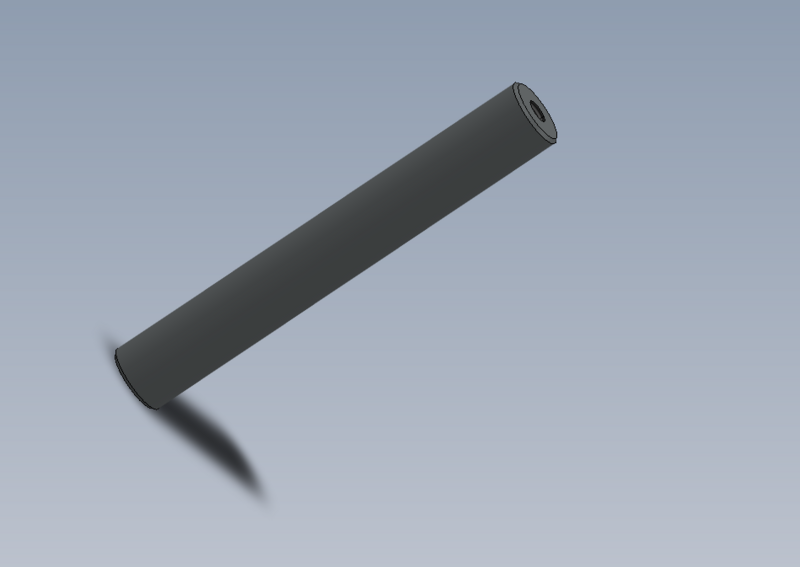
D0007629 Cylinder rod Extension x 4
D0007732 Sprocket Idler Shaft x 2
D0007733 Sprocket Mounting Block x 2
D0008090 Retaining Collar x 1
H0007715 Z Sprocket 33 Teeth 3/8'' pitch x 2
H0007790 Leadscrew Z(Includes Re-balling) x 2
P0000007 Straight Adaptor 6mm - 1/8 BSP tapered thread x 2
P0000010 Elbow Adaptor 6mm - 1/8 BSPT (Taper thread) x 2
P0000023 Fitting: Hex Nipple 1/8 BSP x 2
P0000024 Fitting: Hex Nipple 1/4 BSP x 2
P0000026 Silencer 1/4 BSP x 4
P0000051 Fitting: Straight Adaptor 6mm - 1/4 BSPT x 4
P0000140 Fitting: Quick Exhaust Valve 1/8" x 2
P0000145 Tee-Equal 1/4BSP Galvanised x 2
P0000200 Elbow Adaptor 6mm - M5 x 2
P0000229 Pneumax VDMA 40 x 300 Magnetic x 4
P0001038 Fitting: SMC 1/8" BSP to Ø6mm Elbow White x 4
P0001174 Fitting: Pilot Check Valve 1/4" (Flow & ZX) x 2
Étape 1 - Unless otherwise stated
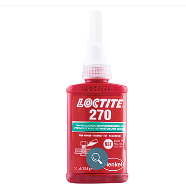
Use locktite 243 on all fasteners
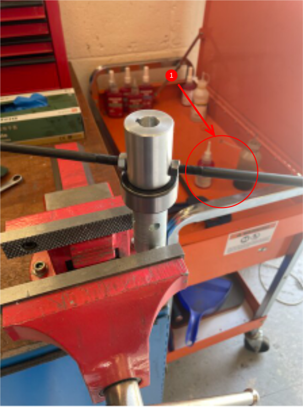
Use loctite 572 on all threaded pneumatic connection
Pen mark all fasteners to show finalised
Étape 4 - Assemble support cylinder 2
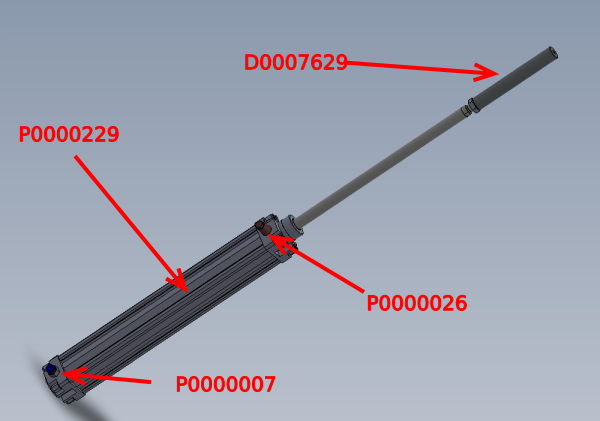
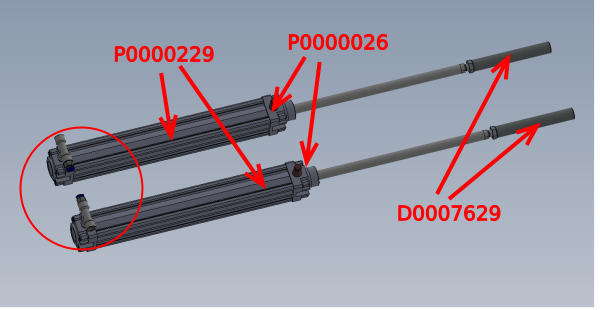
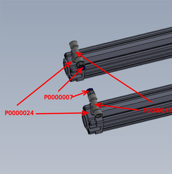
Assemble a pair of cylinder assemblies as shown
PHOTOS REQUIRED
additionally fitted parts are
P0001038 Fitting: SMC 1/8" BSP to Ø6mm Elbow White x 4
P0001174 Fitting: Pilot Check Valve 1/4" (Flow & ZX) x 2
P0000140 Fitting: Quick Exhaust Valve 1/8" x 2
P0000200 Elbow Adaptor 6mm - M5 x 2
Étape 5 - Assemble tensioners
2 off
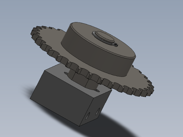
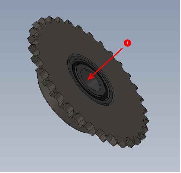
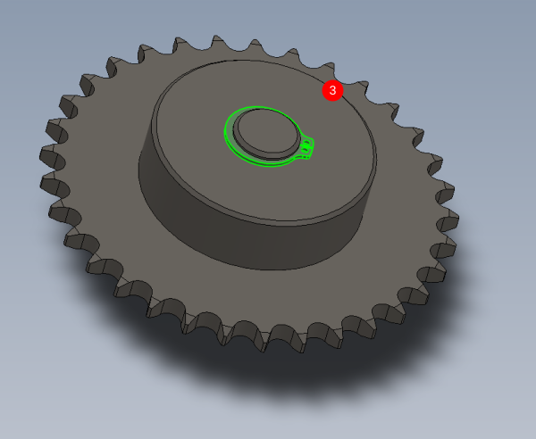
1 Press B0000351 Bearing 40mm O/D 17mm I/D 17.5mm Wide into H0007715 Z Sprocket 33 Teeth 3/8'' pitch . Observe fit, if loose solvent to degrease and apply bearing fit. If tight inspect drawing and check bore size
2 Press in D0007732 Sprocket Idler Shaft , again observing fit as above
3 Fit 16mm external circlip
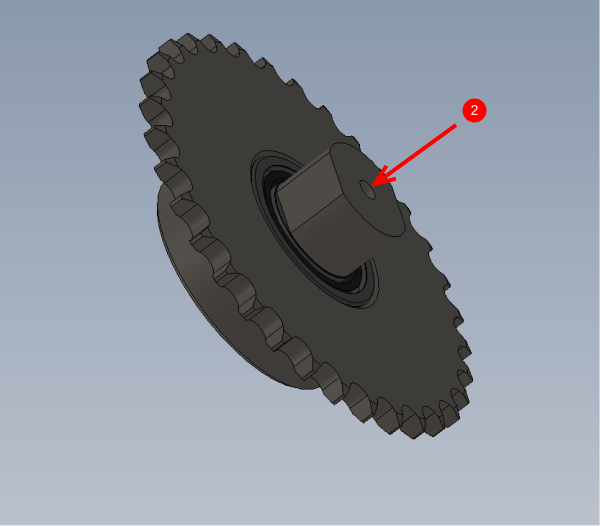
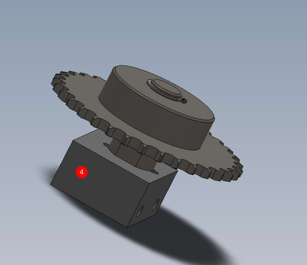
4 Attach D0007733 Sprocket Mounting Block using M6 x 40 socket cap and heavy M6 washer (do not apply adhesive to this bolt )
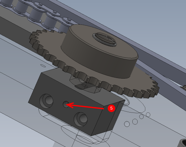
5 Add M6 x 30 grubscrew and M6 standard nut to indicated face (picture required)
Étape 6 - Check fit of D0001926
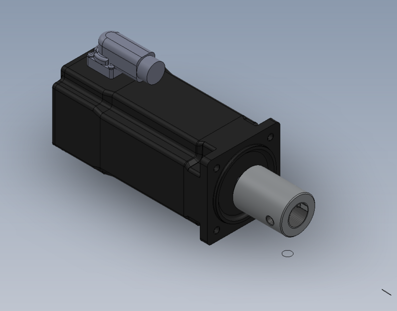
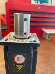
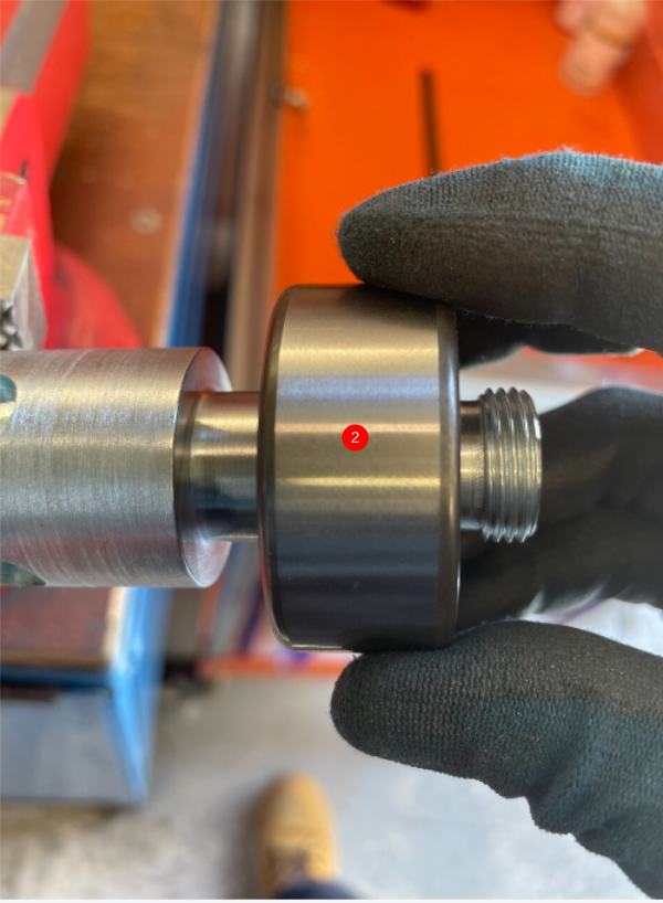
Ensure D0001926 Servo Drive Coupling M20 (Ø14mm) Beckhoff x 1
fits onto C0001122K Servo Motor: Beckhoff AM8032-1E10 (Keyed) x 1
Fit should be a snug slide fit
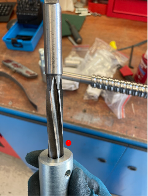
Part can be reamed with hand reamer if fit is tight
Étape 7 - Fit bearing
2 off
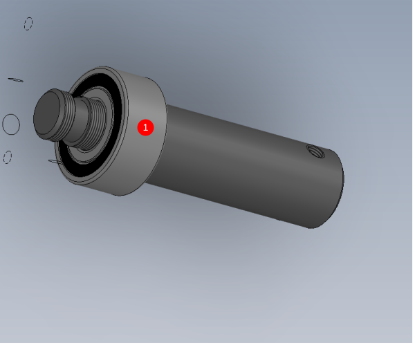
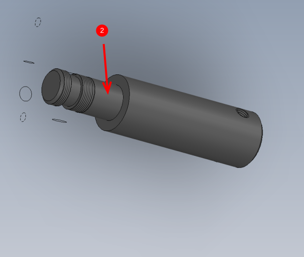
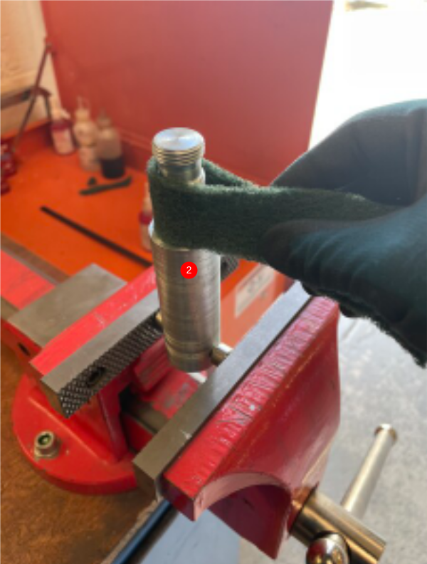
1 Check and adjust fit of B0000139 Double Angular Bearing 20 D 47 D 20.6 Long + seals onto D0006501 Y Leadscrew Sleeve
2 Fit should be a smooth press fit onto sleeve. Indicated face can be polished down with fine emery to obtain desired fit
Étape 8 - Tension drive coupling
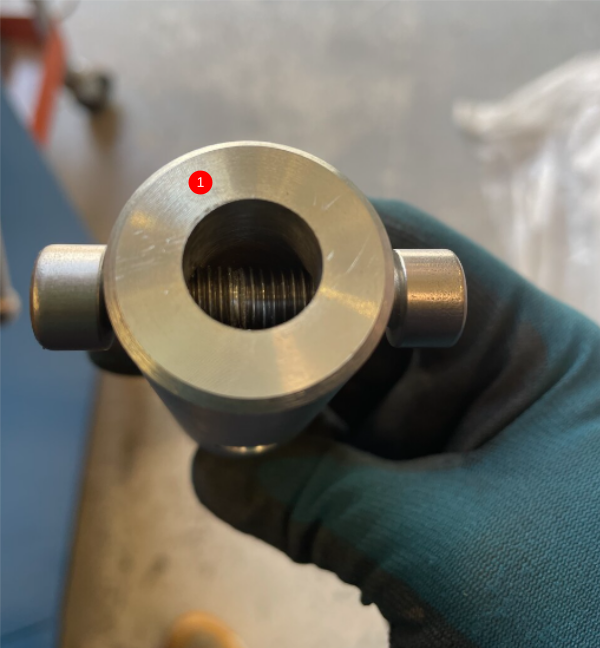
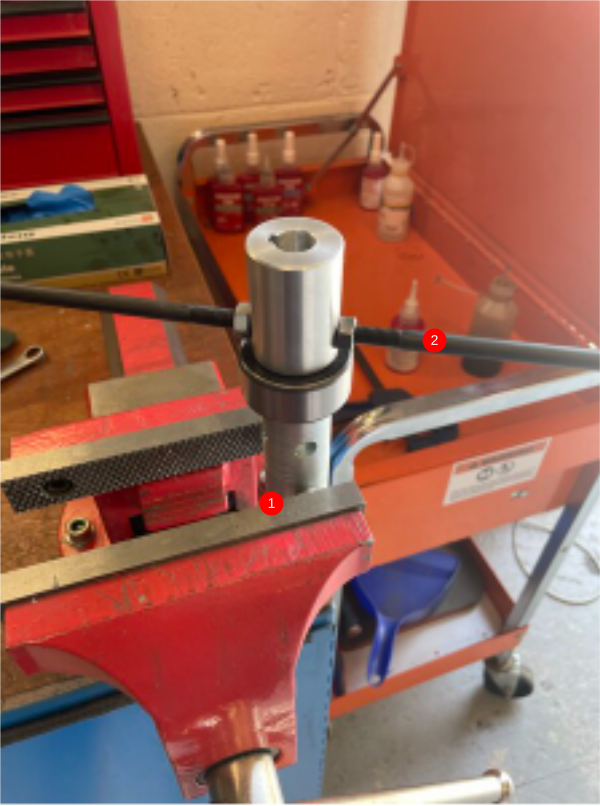
1 Add m8 socket caps as shown to hold assembly in vice
2 Use 2 off m8 long socket caps and Standard M8 nuts and lock onto drive coupling .
Tension using long M8s as leverage
Étape 9 - Finalise drive coupling
1 off
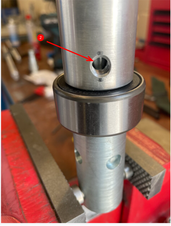
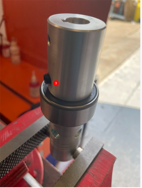
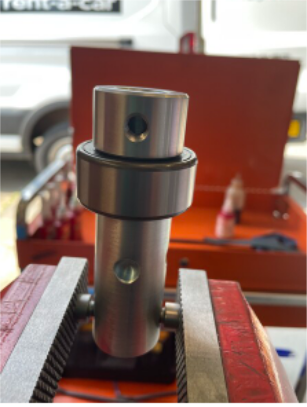
1 Remove 1 off Long M8 socket cap and tension an M8 x 12 kcp grubscrew into the hole (do not add adhesive )
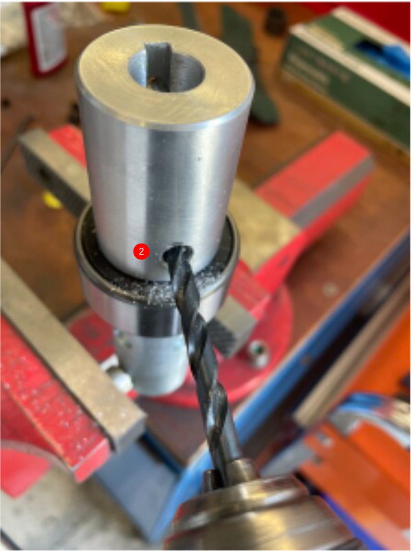
2 Remove second Long M8 socket cap and dimple inner shaft using 6.8mm drill
Clean with compressed air and add M8x 8 kcp with adhesive and tension
3 Remove m8 x 12 kcp grub screw and repeat above step
Étape 10 - Finalise idler coupling
1 off
Use the same steps above to assemble idler drive coupling as shown using D0008090 Retaining Collar x 1
Étape 11 - Check fit of leadscrew to coupling
2 off
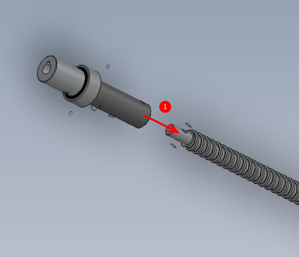
1 Check fit of coupling to leadscrew H0007790 Leadscrew
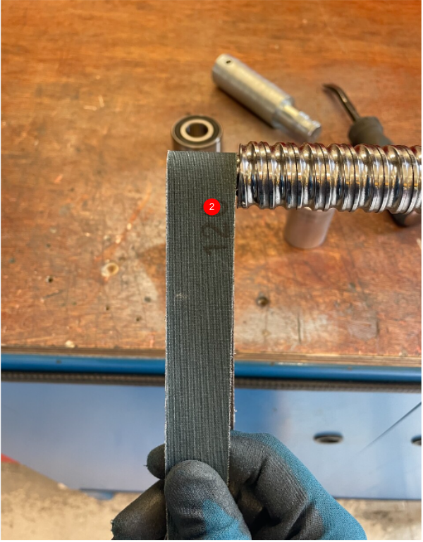
2 Use reamer / Emery tape if fit is tight
Étape 12 - Check bearing fit
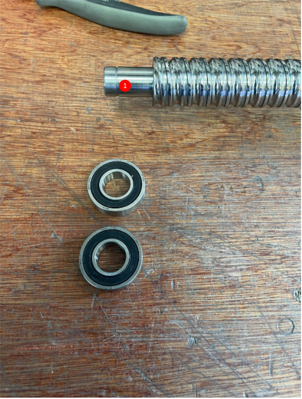
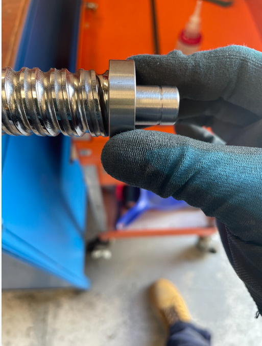
1 Check bearing B0000086 Ball Bearing 15 D 32 D 9 Long + seals fit is acceptable on leadscrew H0007789
2 Adjust with emery tape if fit is tight
Draft
 Français
 English
 Deutsch
 Español
 Italiano
 Português