Installation and Alignment criteria for Autoflow Mk4

Difficulté
Difficile
Durée
2 jour(s)
Sommaire
- 1 Introduction
- 2 Étape 1 - Machine Location/Position
- 3 Étape 2 - Module A Infeed table
- 4 Étape 3 - Levelling Datums
- 5 Étape 4 - Infeed Table Levelling Process
- 6 Étape 5 - Adjust remaining pads
- 7 Étape 6 - Position Machining/Saw unit
- 8 Étape 7 - level datums
- 9 Étape 8 - Set levels
- 10 Étape 9 - Finalise Position Machining centre X axis
- 11 Étape 10 - Finalise Position Machining Centre Y axis
- 12 Étape 11 - Finalise Machining centre height
- 13 Étape 12 - Adjust Centre support
- 14 Étape 13 - laser Alignment Height
- 15 Étape 14 - Laser Alignment Backfences
- 16 Étape 15 - Finalise Front guard Support
- 17 Étape 16 - Assemble JX Axis
- 18 Commentaires
Introduction
Information to clarify correct process for installation of J0001000H Autoflow Mk4
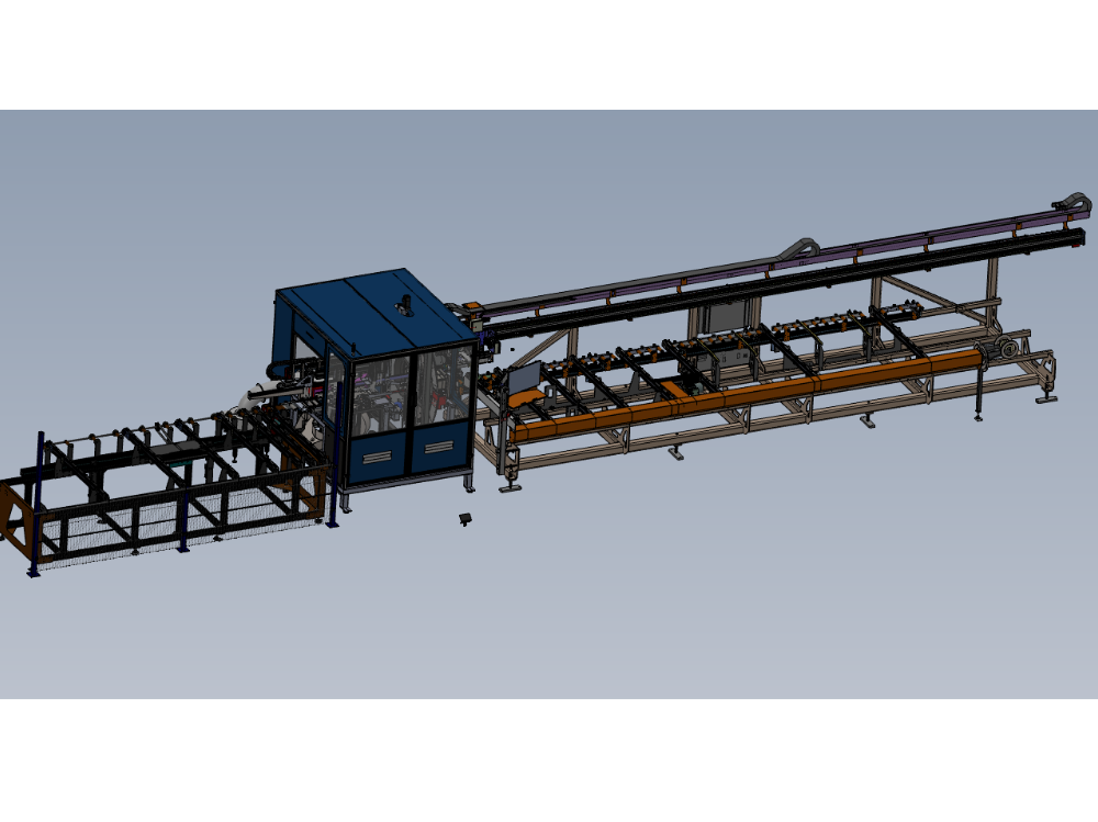
Étape 1 - Machine Location/Position
Use footprint drawing to determine machine location for installation

Étape 2 - Module A Infeed table
Identify correct position for installation of Infeed frame. Ensure consideration is given to walkways and installation of machine guarding at later part of installation

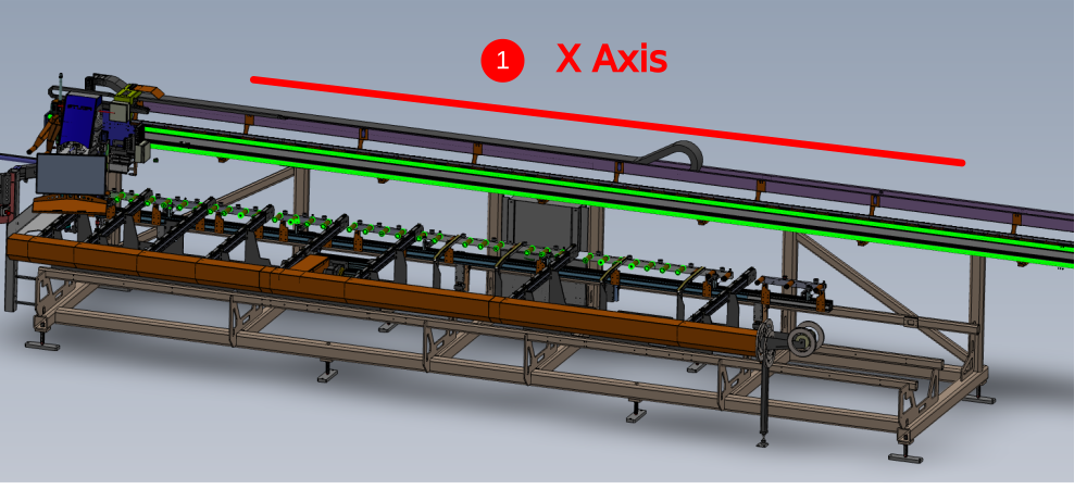
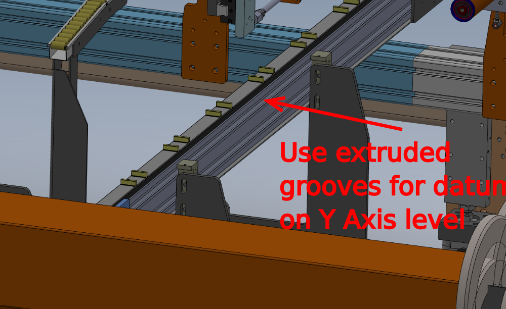
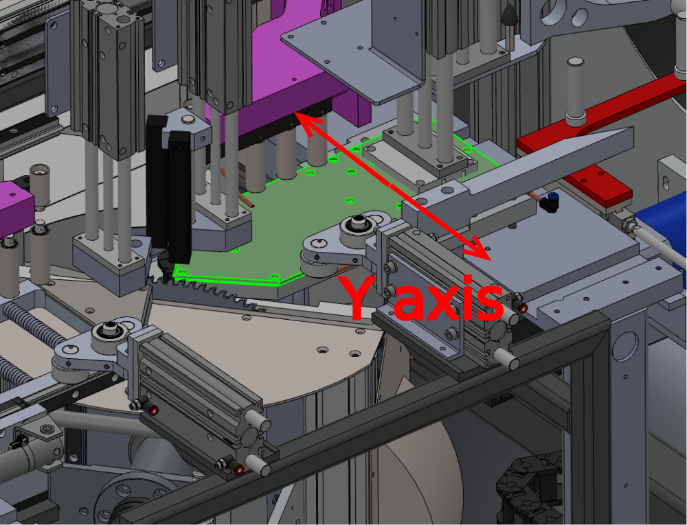
Étape 3 - Levelling Datums
Indicated are the leveling datums for the Infeed table
X Axis as indicated by 1
Y axis as indicated by 2
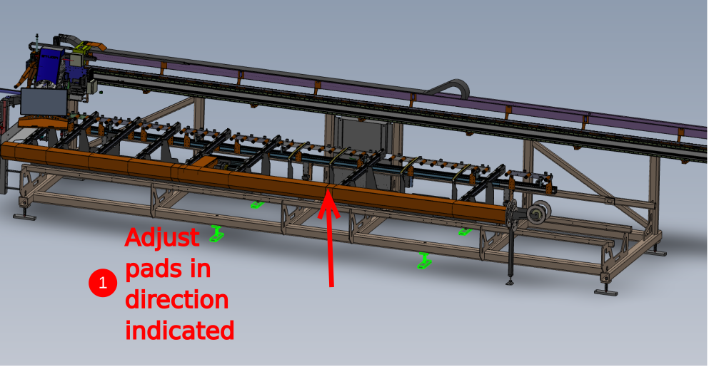
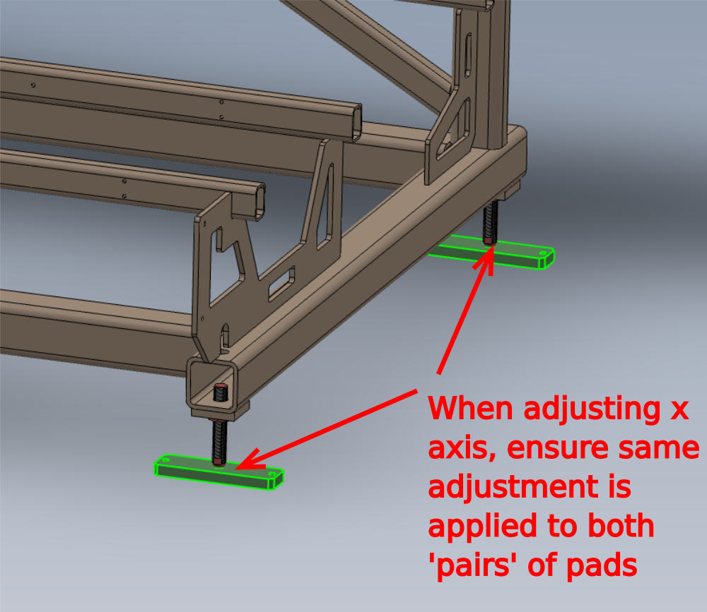
Étape 4 - Infeed Table Levelling Process
1 Ensure indicated central 4 adjusting bolts/ pads are lifted out of the way , so they do not impede the levelling process
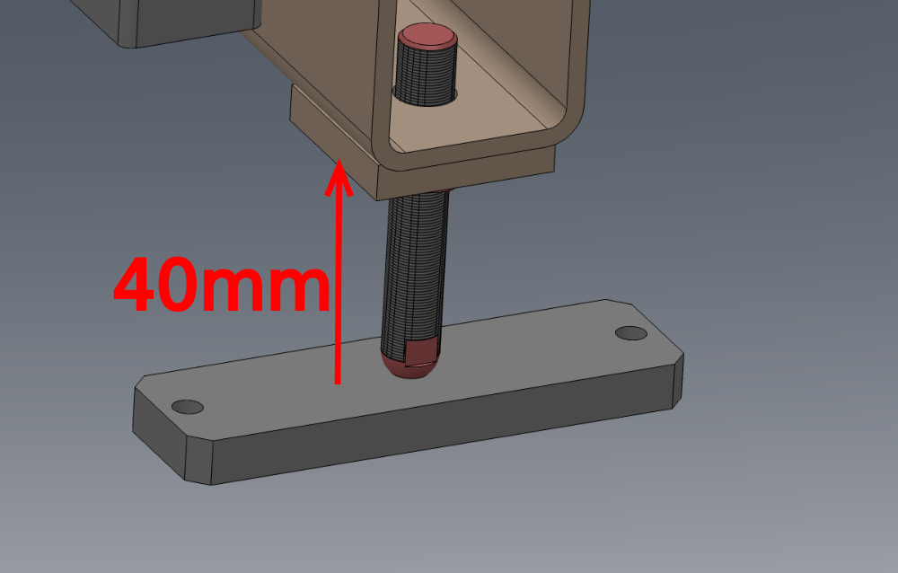
2 Set gap of indicated pads to the starting measurement shown of 40mm
3 Adjust Y axis position to read level at indicated points using pads indicated in number 2 only
4 Adjust X axis position using same pads as previous,and ensure Y axis level is not compromised by adjusting pads in pairs
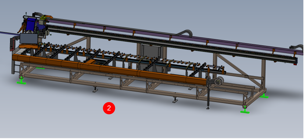
Étape 5 - Adjust remaining pads
Remaining pads should now be adjusted down to touch floor.
Ensure no additional pressure is applied to they which will cause levels to be affected

Étape 6 - Position Machining/Saw unit
Position Module B/F into the approximate area according to the floor plan

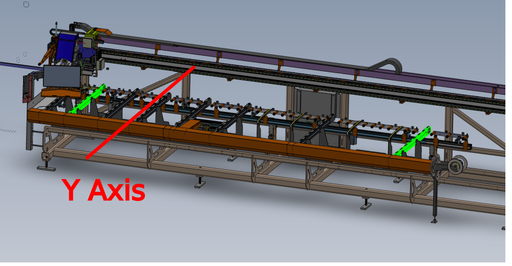
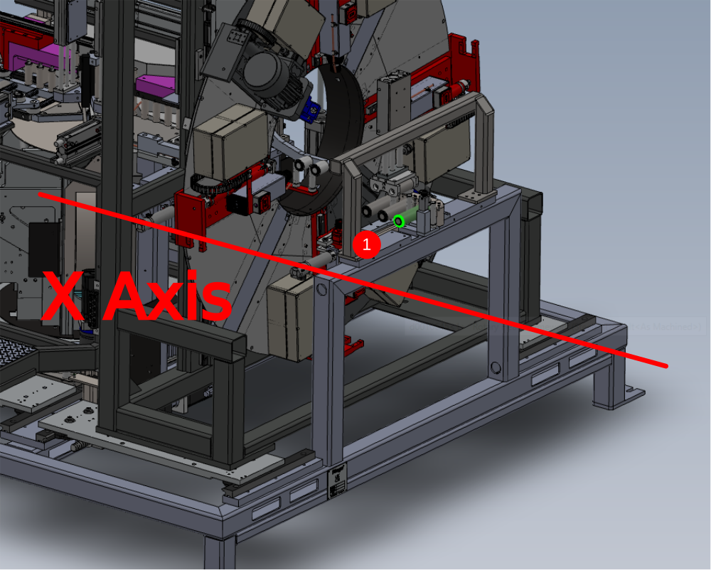
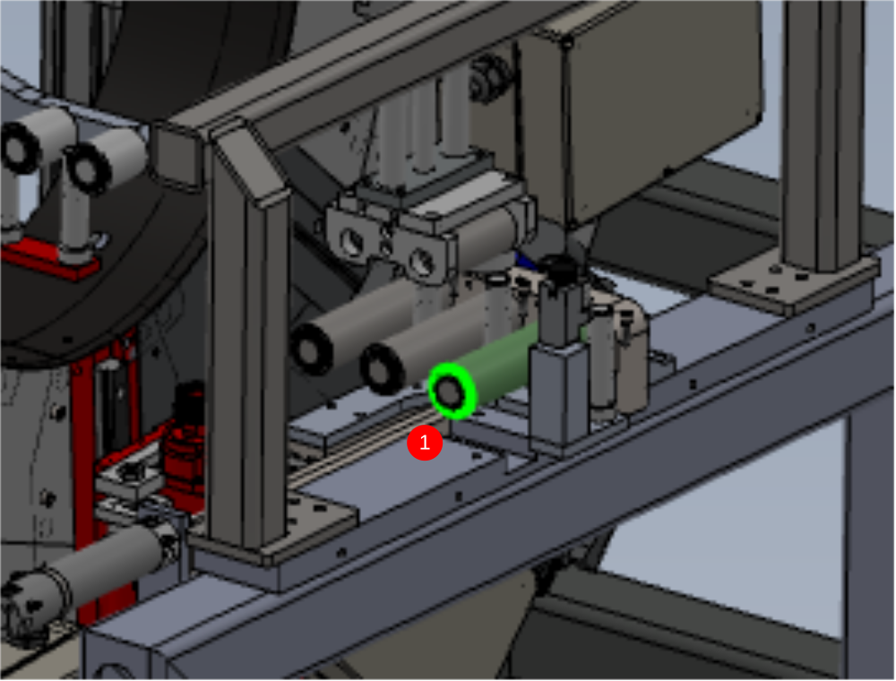
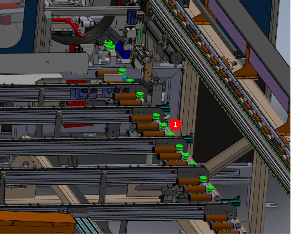
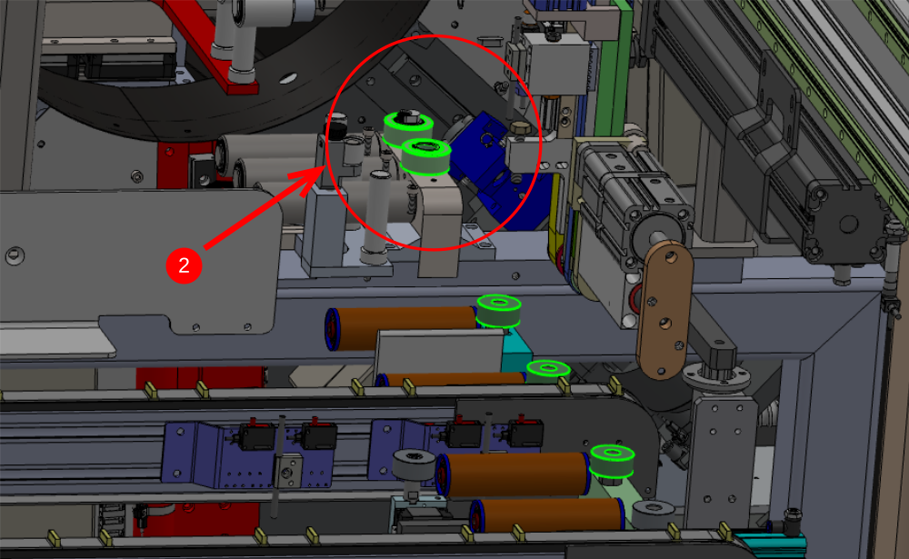
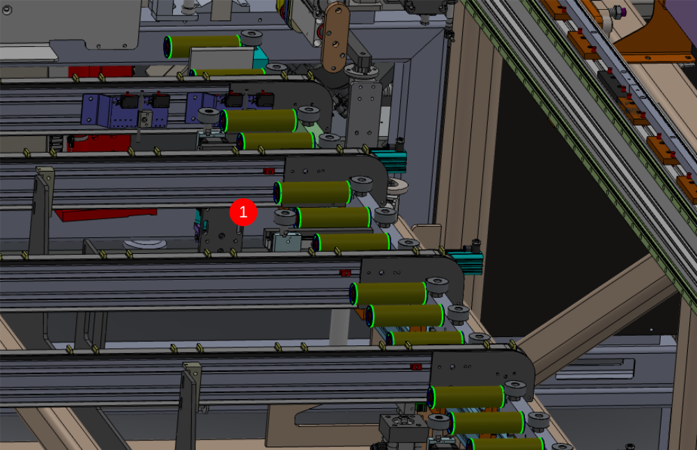
Étape 7 - level datums
Datums for levels are as shown
1 X Axis . Only first and last datum rollers should be used initially for levelling
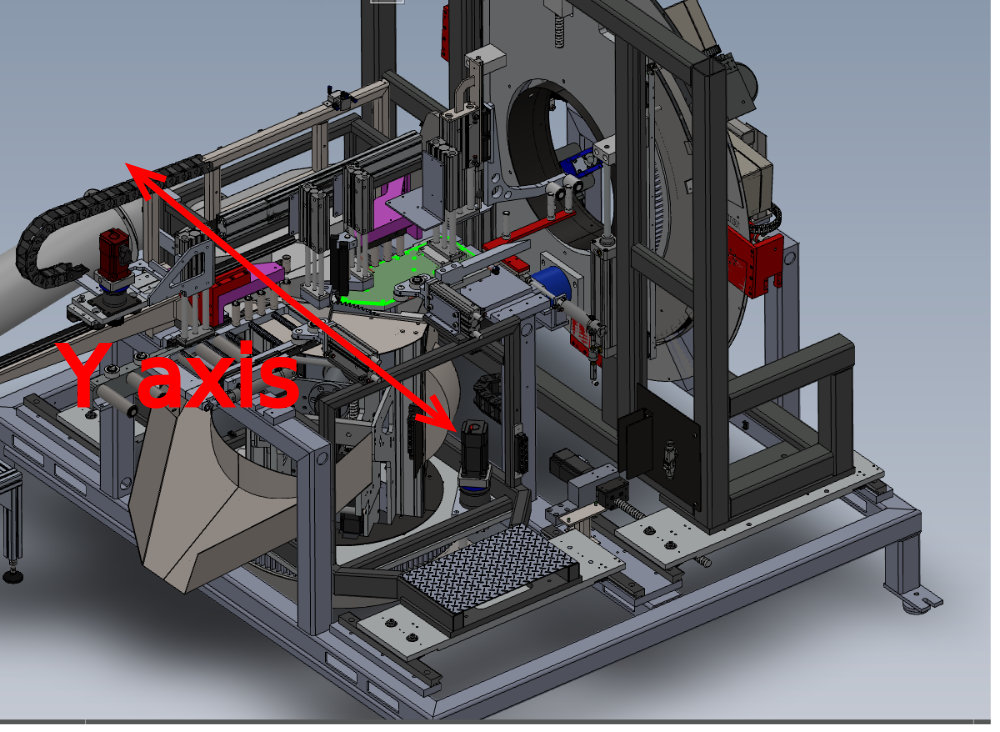
2 Y Axis should be set from fixed cut table
Étape 8 - Set levels
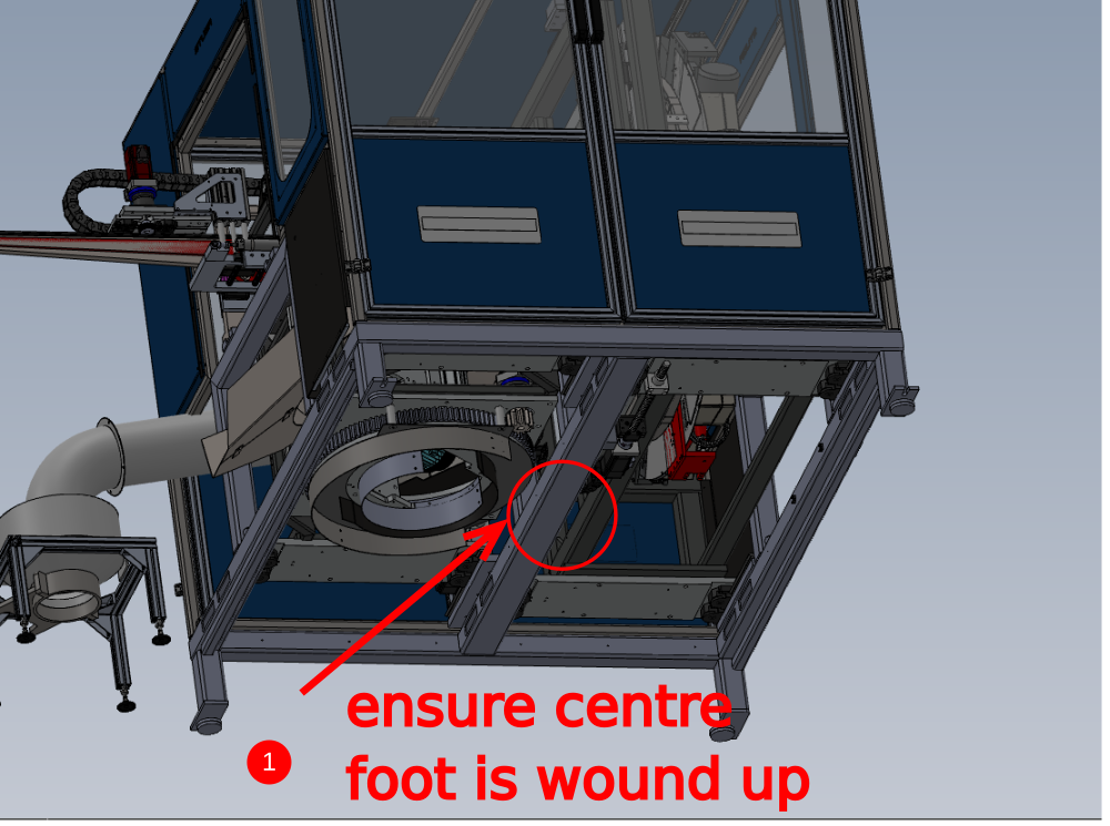
1 Ensure centre support foot is wound up away from floor to not impede initial level setting
2 Use a 2 meter straight edge and engineers level to bridge between 2 indicated datum points for X axis datum . Adjust perimeter pads only to bring this level (centre rollers tables may appear low when straight edge is used. This is normal and will be adjusted out later)
3 Use engineers level on the indicated face to adjust Y axis level. Ensure floor pads are adjusted in pairs to maintain X axis level that has been set
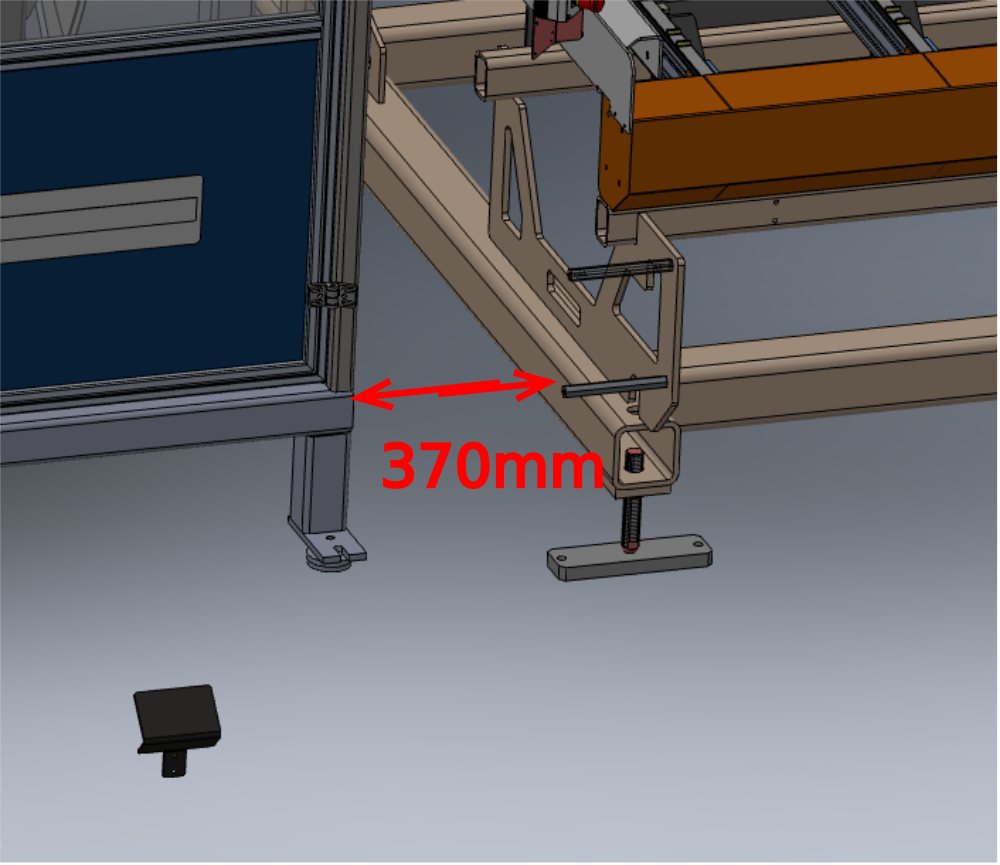
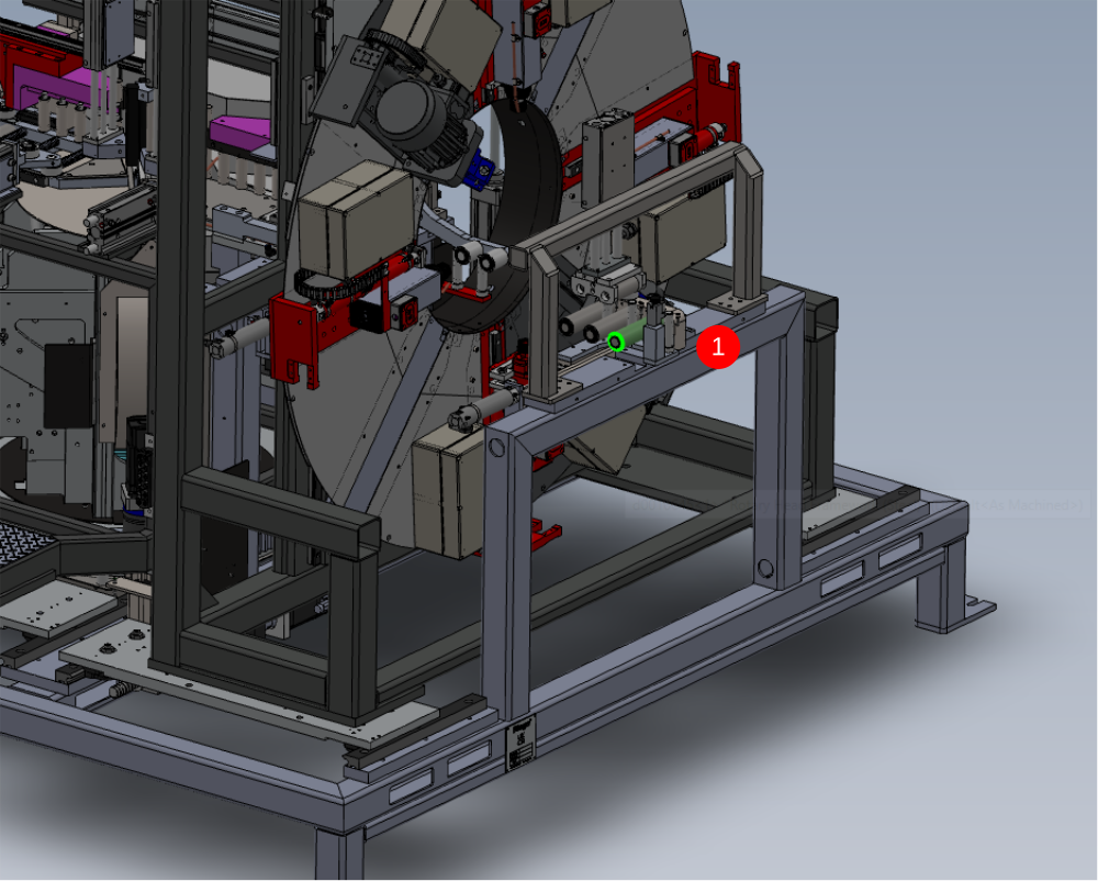
Étape 9 - Finalise Position Machining centre X axis
Spacing between Infeed and Machining centre should be set to 370mm as indicated. This measurement is taken from internal faces of frame box section.
Étape 10 - Finalise Position Machining Centre Y axis
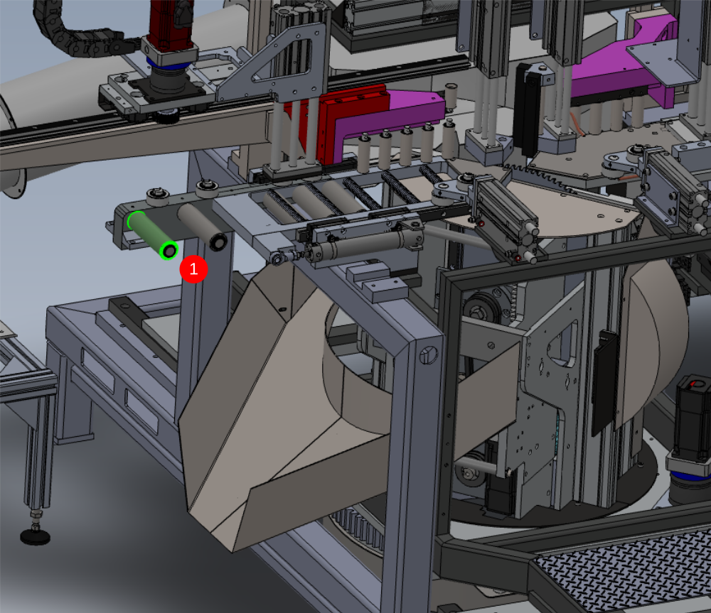
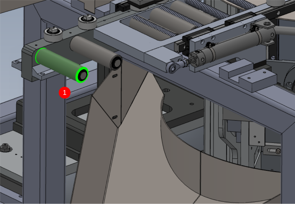
1 Use 2 meter straight edge against indicated rollers on infeed table .
2 Adjust position of Machining centre so indicated rollers align to straight edge set against infeed rollers
Étape 11 - Finalise Machining centre height
1 Use 2 meter straight edge on indicated rollers to project height to Machining centre
2 Use indicated rollers to accept projection from Infeed table
3 Adjust 4 corner pads of Machining centre equally to match height to straight edge .
4 Increase height of Machining centre by 0.5mm to allow slight bump up from Infeed rollers to Machining centre

Étape 12 - Adjust Centre support
1 Centre support foot can now be set on Machining centre. Insert 2 meter straight edge and bridge 2 datum points for x axis on the machining centre ( same as previous step)
2 If all rollers are contacting straight edge, adjust centre support to take weight of Machining centre but not adjust roller position
3 If discrepancy is visible, centre support can be adjusted to align centre rollers to straight edge

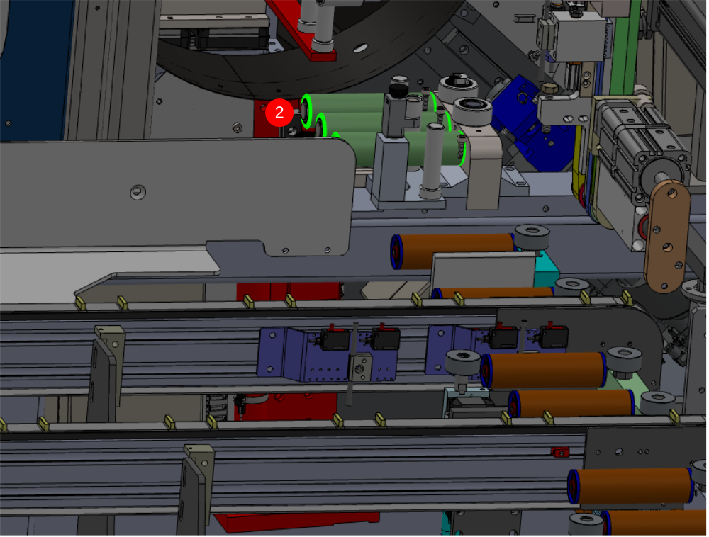
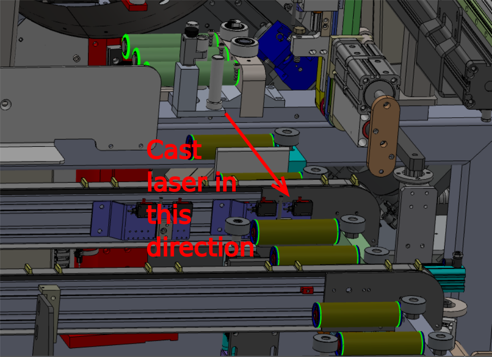
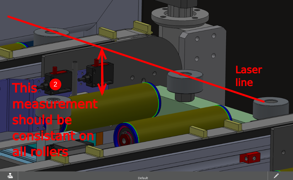
Étape 13 - laser Alignment Height
Laser alignment is now required to ensure all alignment is correct
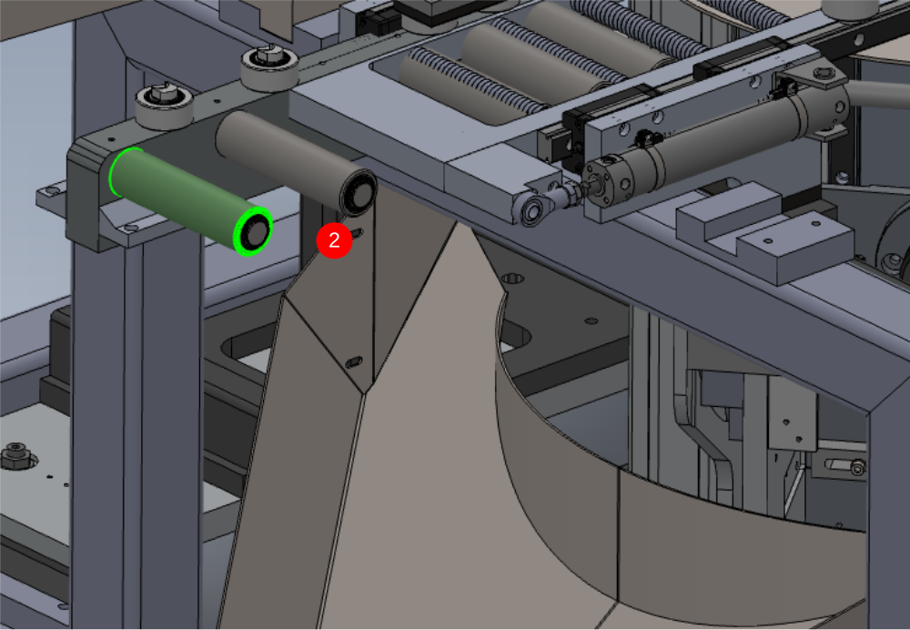
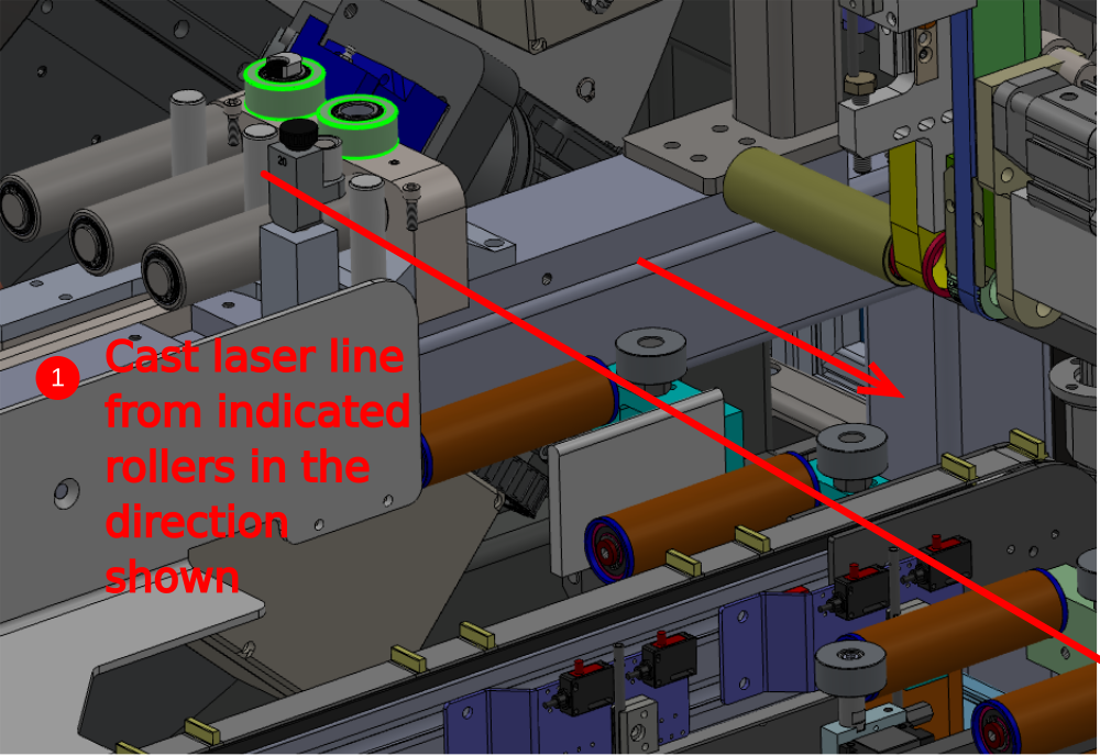
1 Use a laser to cast from indicated rollers in the direction shown
2 Ensure measurement indicated is constant on every roller on infeed table
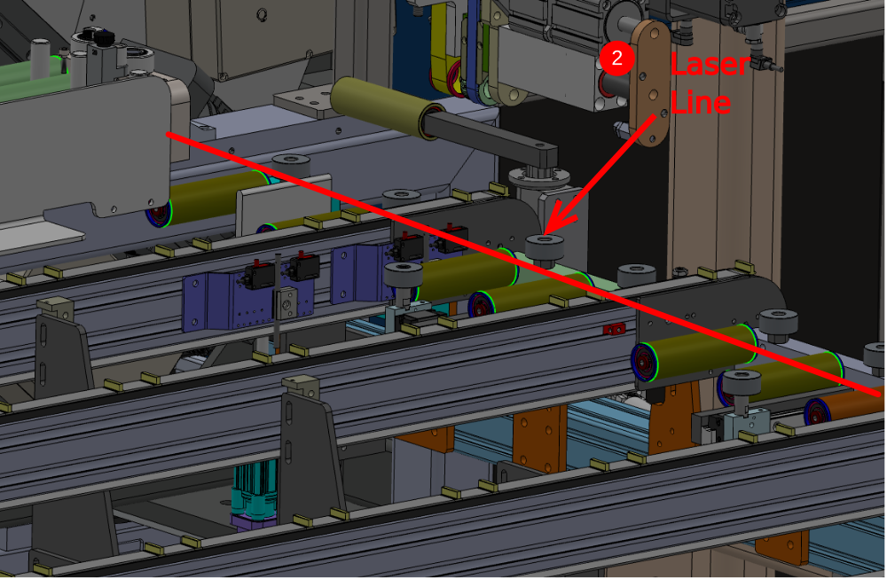
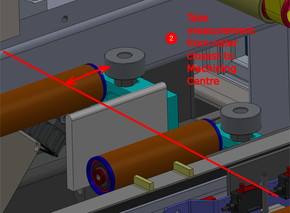
Étape 14 - Laser Alignment Backfences
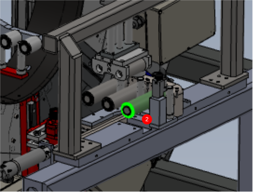
1 Use a laser to cast from the indicated point in the direction shown
2 Take indicated measurement From roller closest to Machining centre
3 Take the same measurement at the last roller on the Infeed. These measurements need to be the same to ensure correct alignment
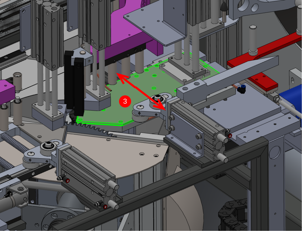
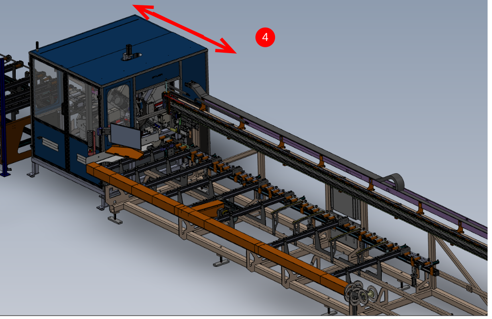
4 If the measurement is different, the Machining centre will require adjusting slightly to correct this pivot the Machining centre Rear in the indicated directions to correct laser error
5 Recheck Step 10 if adjustments are made
All Previous parameters for alignment must be rechecked (steps 7 to 13) once final adjustments have been done
Étape 15 - Finalise Front guard Support
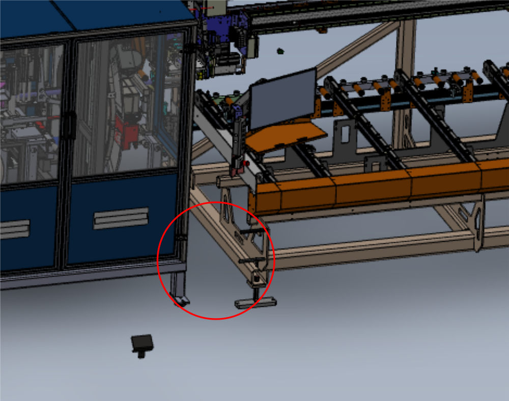
Now alignment between Infeed table and Machining centre is complete , the front tray support can set
Adjust support so front tray is held level to rest of assembly


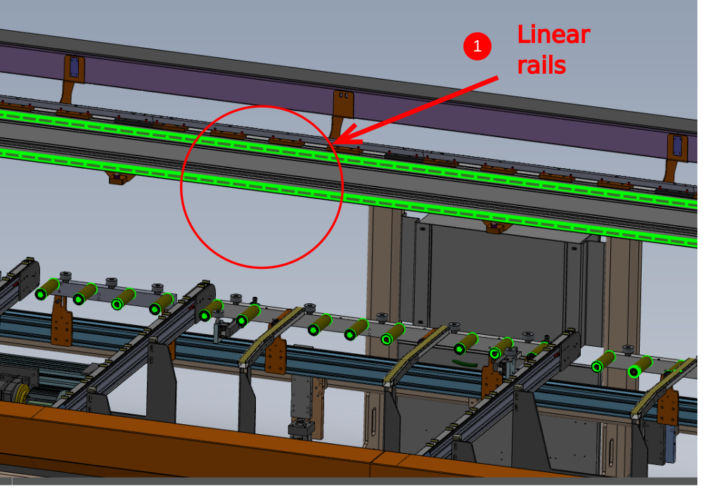
Étape 16 - Assemble JX Axis
The JX axis requires assembling to allow setting of the outfeed table
Draft
 Français
 English
 Deutsch
 Español
 Italiano
 Português