Installation and Alignment criteria for Autoflow Mk4

Difficulté
Difficile
Durée
2 jour(s)
Introduction
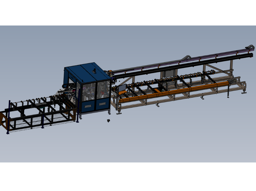
Information to clarify correct process for installation of J0001000H Autoflow Mk4
Étape 1 - Machine Location/Position
Use footprint drawing to determine machine location for installation

Étape 2 - Module A Infeed table
Identify correct position for installation of Infeed frame. Ensure consideration is given to walkways and installation of machine guarding at later part of installation

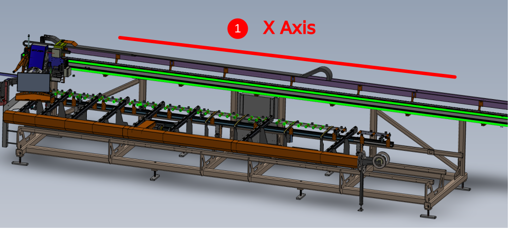
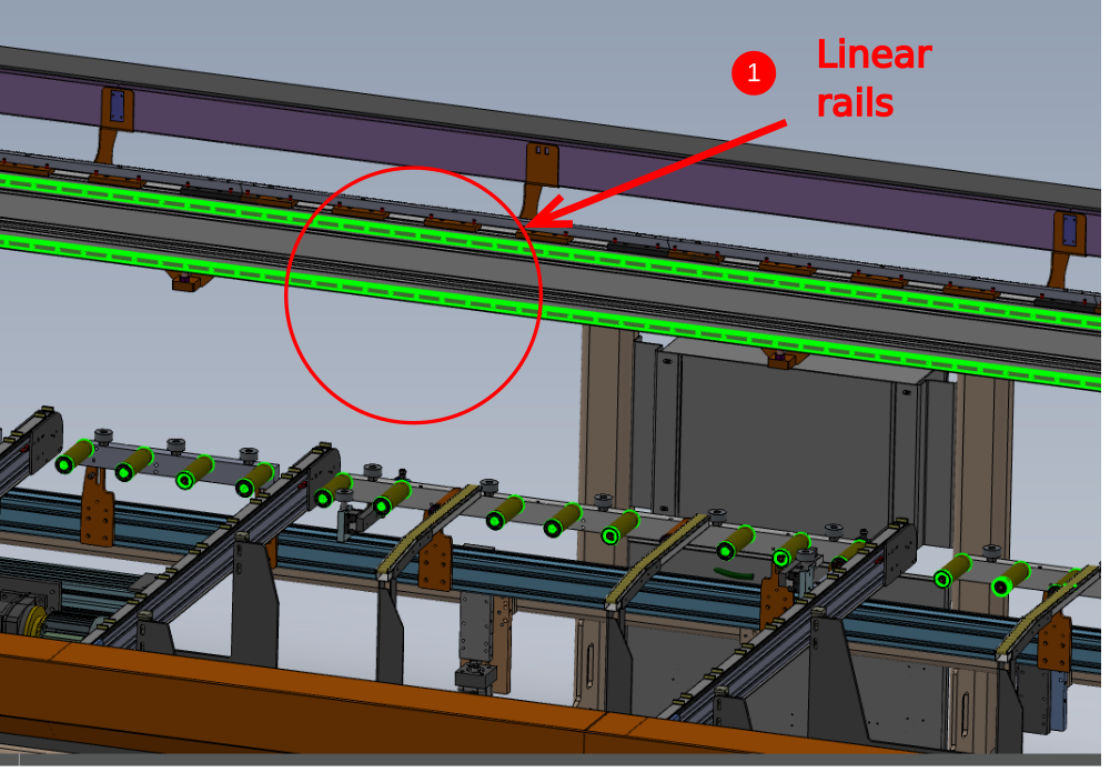
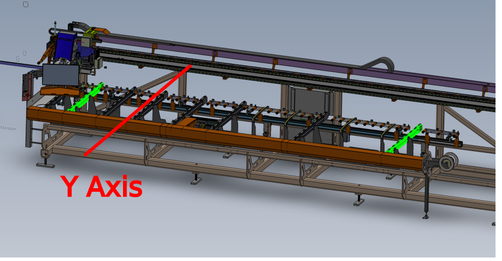
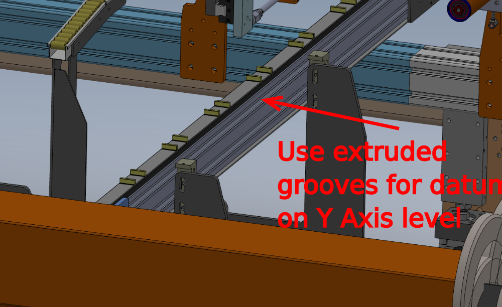
Étape 3 - Levelling Datums
Indicated are the leveling datums for the Infeed table
X Axis as indicated by 1
Y axis as indicated by 2
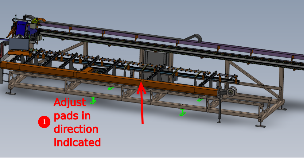
Étape 4 - Infeed Table Levelling Process
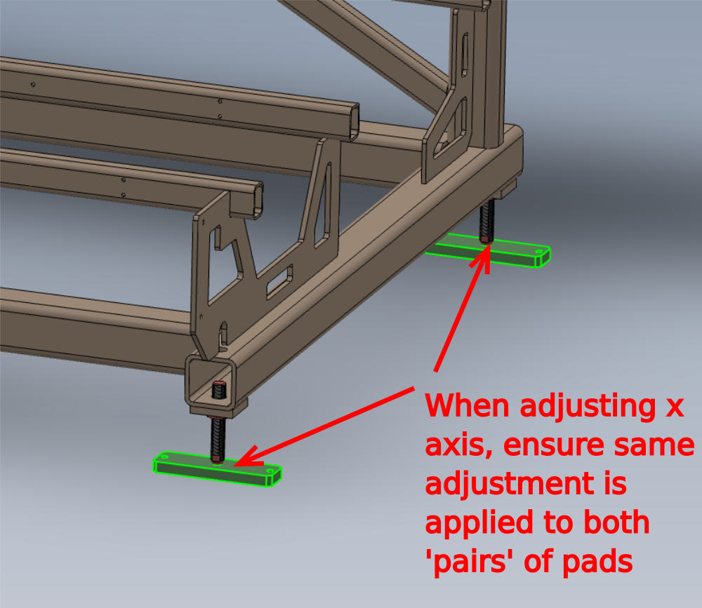
1 Ensure indicated central 4 adjusting bolts/ pads are lifted out of the way , so they do not impede the levelling process
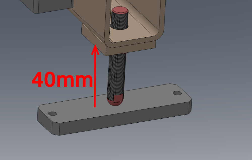
2 Set gap of indicated pads to measurement shown of 40mm
3 Adjust Y axis position to read level at indicated points using pads indicated in number 2 only
4 Adjust X axis position using same pads as previous,and ensure Y axis level is not compromised by adjusting pads in pairs
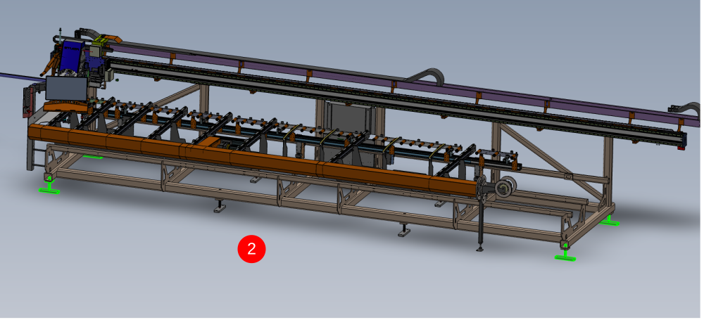
Étape 5 - Adjust remaining pads
Remaining pads should now be adjusted down to touch floor.
Ensure no additional pressure is applied to they which will cause levels to be affected

Étape 6 - Position Machining/Saw unit
Position Module B/F into the approximate area according to the floor plan

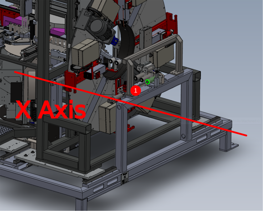
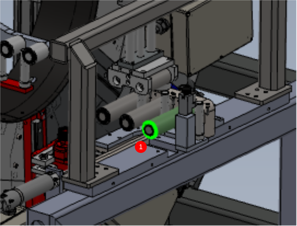
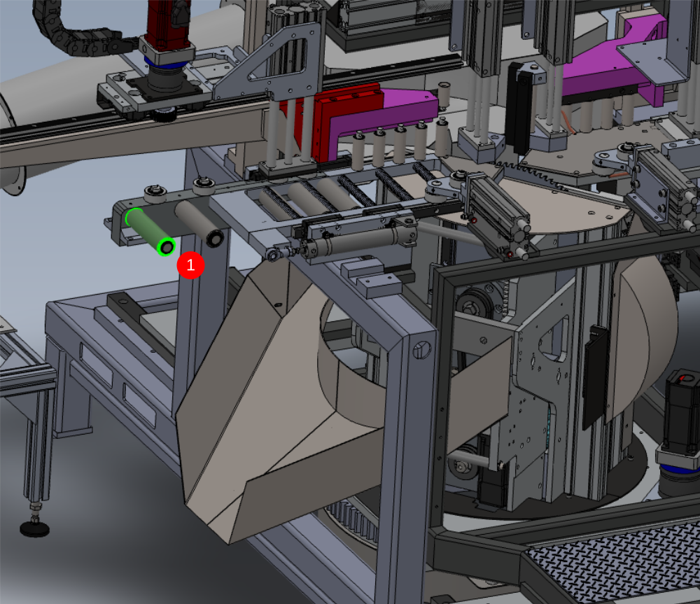
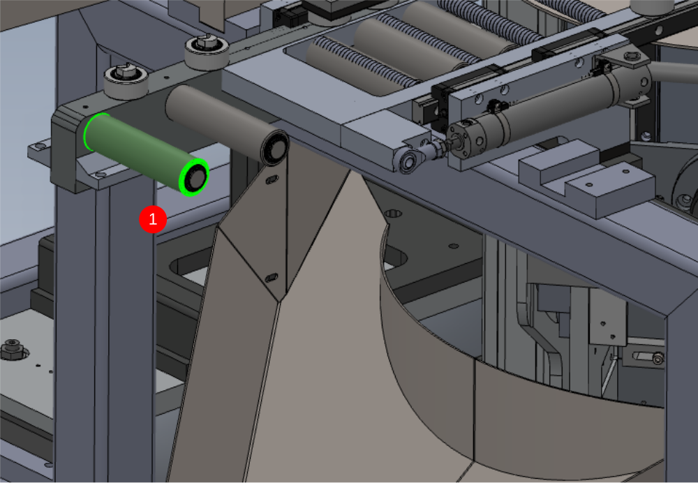
Étape 7 - 1st stage level datums
Datums for levels are as shown
1 X Axis . Only first and last datum rollers should be used initially for levelling
2 Y Axis
Draft
 Français
 English
 Deutsch
 Español
 Italiano
 Português