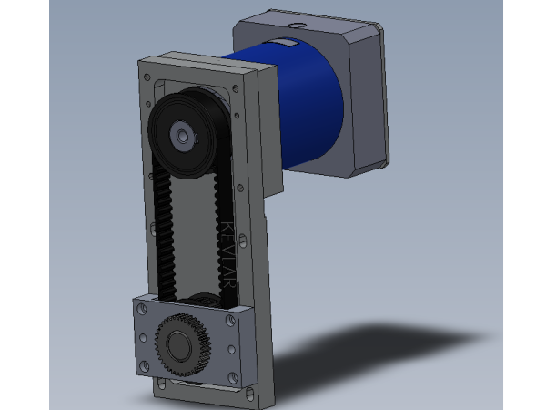
Assembly instructions for R axis gearbox
Sommaire
- 1 Introduction
- 2 Étape 1 - Unless otherwise stated
- 3 Étape 2 - Assemble drive spigot
- 4 Étape 3 - fit key and pulley
- 5 Étape 4 - Attach to gearbox plate
- 6 Étape 5 - Gear box bung supplied with gearbox C0001211
- 7 Étape 6 - Check pulley fitment
- 8 Étape 7 - Fit Servo gearbox cap
- 9 Étape 8 - Couple and align gearbox and pinion assembly
- 10 Étape 9 - Align pulleys
- 11 Étape 10 - Remove pulley assembly
- 12 Étape 11 - Tension belt
- 13 Étape 12 - finalise position
- 14 Étape 13 - Quality check
- 15 Commentaires
Introduction
Tools Required
Standard hex key set
Standard spanner set
Tensioning jig
Standard HSS drill set
300mm rule
Parts Required
B0000062 Circlip 20mm External x 2
B0000092 Belt: Toothed 640-8MGT 20 (R Axis) (KEVLAR) x 1
B0000095 Bearing NR6004 2RS with snap ring (NSK) x 2
C0001211 Gearbox NP035s 5:1 x 1
D0000268 Rotary Drive Tooth Pulley x 1
D0001286B-2MOD Welded Ring Pinion Gear 2MOD (for 8mm key) x 1
D0006058 Gearbox Plate x 1
D0006060 Spigot Cap x 1
D0007849 Servo gearbox cap x 1
D0008585B Rotary Ring Drive Pulley (for 8mm key) x 1
D0015801 Feather Key 8mm x 8mm x 22mm x 1
Étape 1 - Unless otherwise stated
Use Loctite 243 on all fasteners
Use Loctite 572 on all threaded pneumatic connection
Pen mark all fasteners to show finalised
Étape 2 - Assemble drive spigot
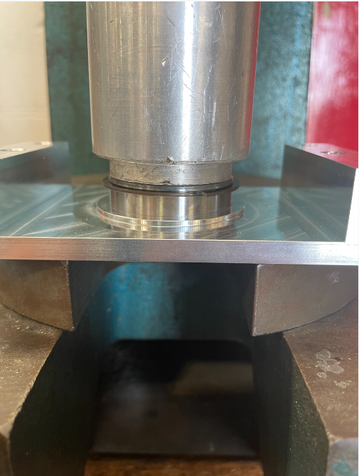
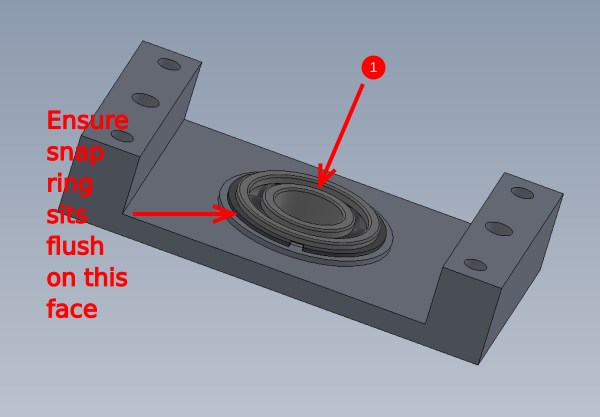
1 Press B0000095 Bearing into D0006060 Spigot Cap so snap ring sits flush
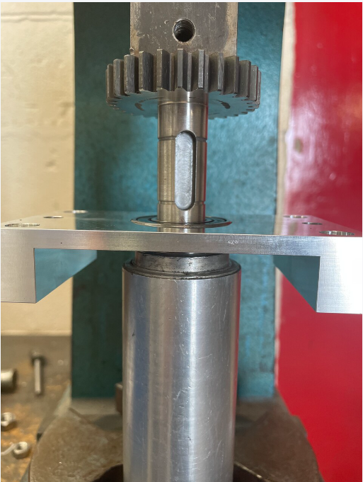
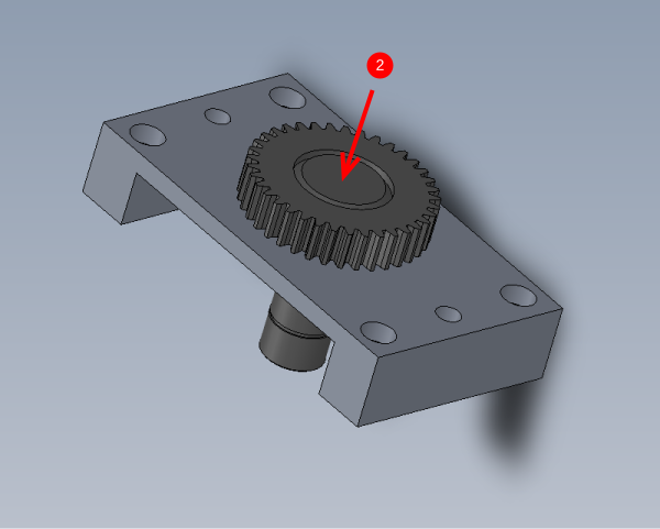
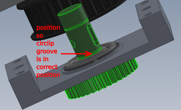
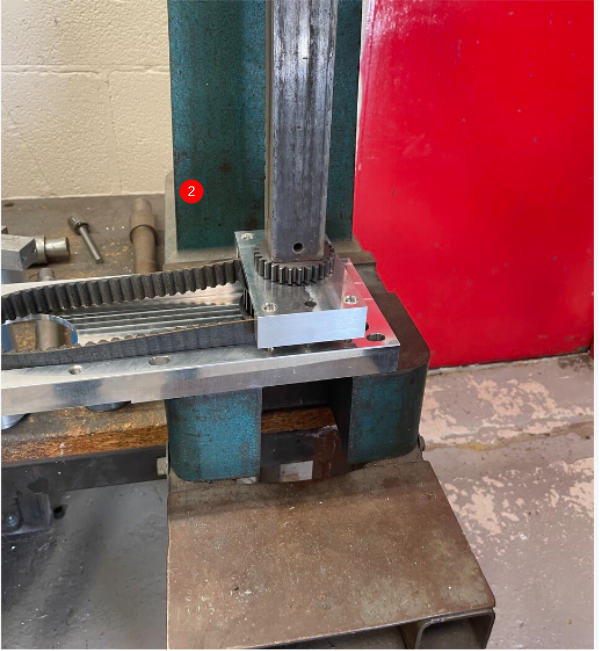
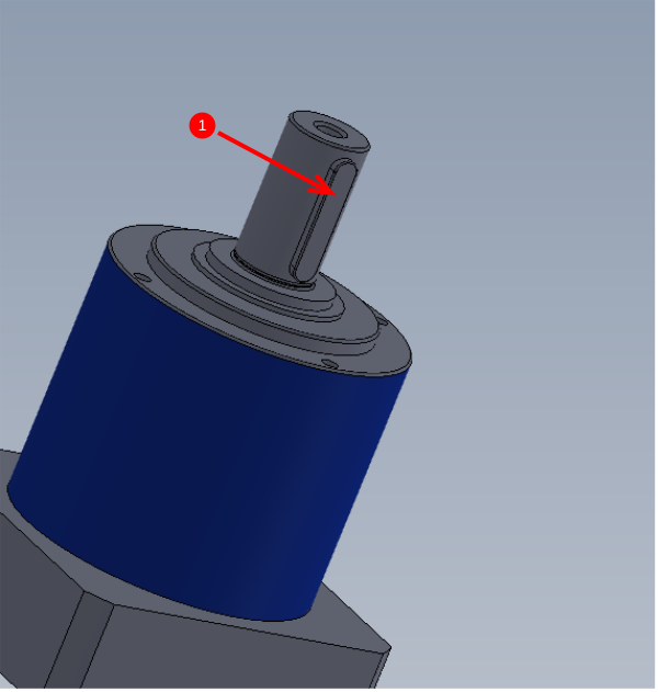
2 Fit D0001286B-2MOD Welded Ring Pinion Gear 2MOD as shown Use jig to ensure bearing is not moved from location. Push through until circlip groove is in correct place
Étape 3 - fit key and pulley
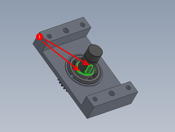
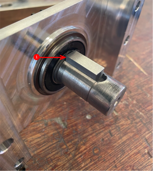
1 Fit Circlip 20mm and D0015801 Feather Key 8mm x 8mm x 22mm as shown
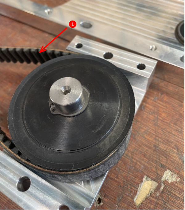
2 Fit D0008585B Rotary Ring Drive Pulley as shown . Only press down until circlip groove is present
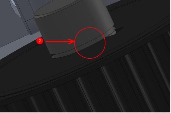
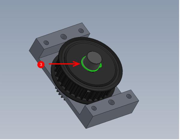
3 Fit 20mm external circlip
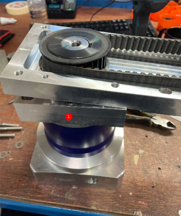
Étape 4 - Attach to gearbox plate
1 Attach B0000092 Belt: Toothed 640-8MGT 20 as shown
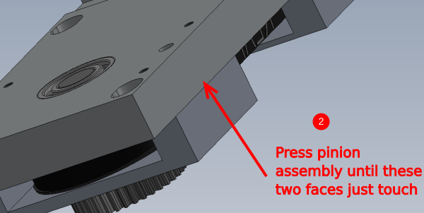
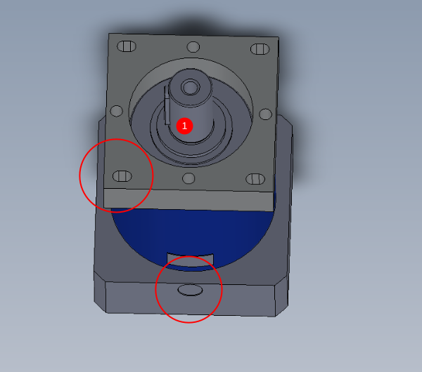
2 Press pinion assembly onto gearbox plate
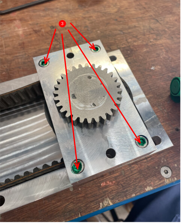
3 Secure lightly with 4 off M6 x 35 socket caps
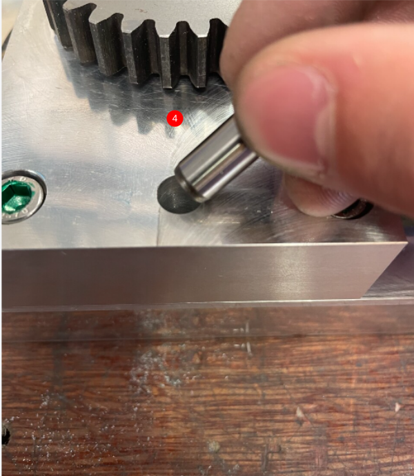
4 Add 2 off 8mm x 50mm dowels into indicated holes . Ream if holes are tight
5 Finalise 4 off M6 socket caps
Étape 5 - Gear box bung supplied with gearbox C0001211
Étape 6 - Check pulley fitment
Check D0000268 Rotary Drive Tooth Pulley fits onto C0001211 Gearbox
If pulley fits move to step 6, if it does not fit follow these steps
1 Remove key from gearbox shaft
2 Test pulley again for fitment.
- If the pulley still does not fit, polish inner face of pulley until fitment is achieved
- if the pulley does fit when the key is removed , move to next step
3 Refit key
4 Test pulley , if the pulley still doesn't fit correctly dress keyway slot gently until fit is achieved
Étape 7 - Fit Servo gearbox cap
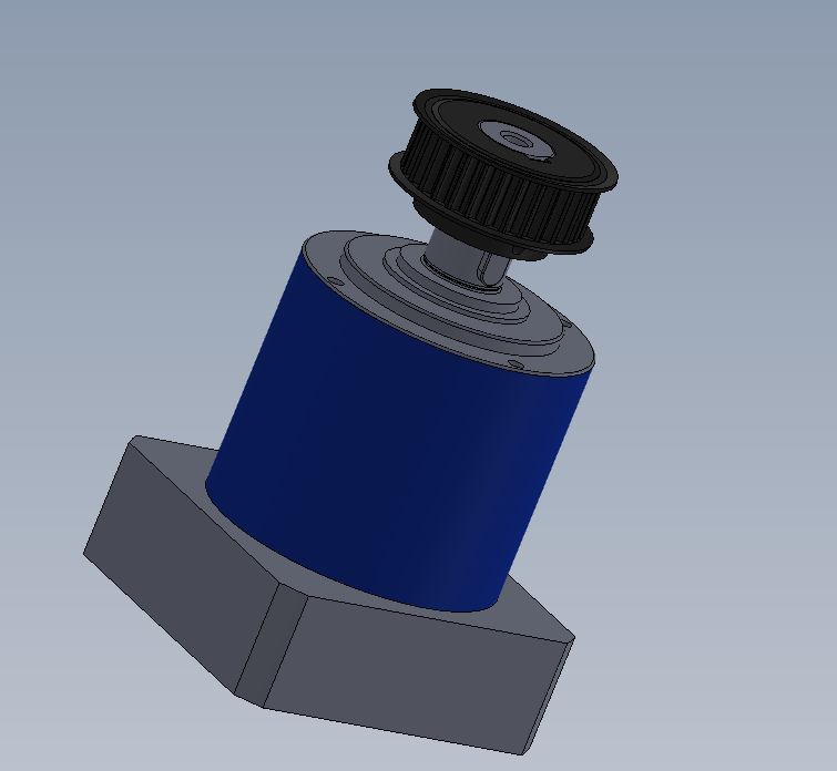
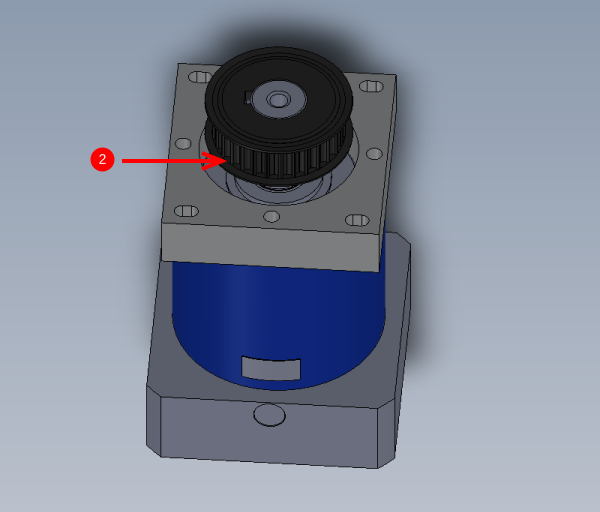
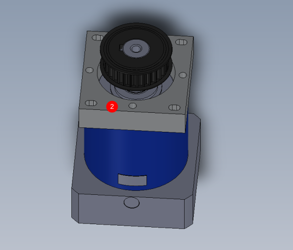
1 Fit D0007849 Servo gearbox cap as shown. No adhesive on the 4 off M8 x 35 socket caps
Orientate as shown
2 Fit D0000268 pulley
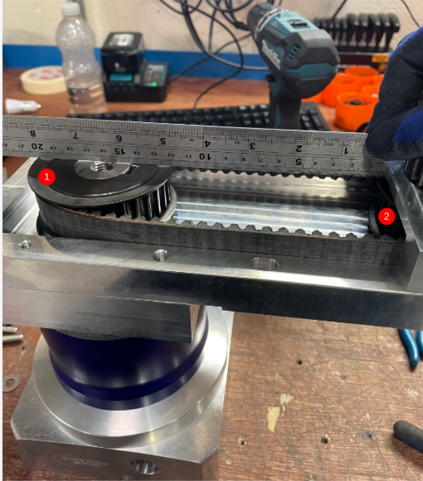
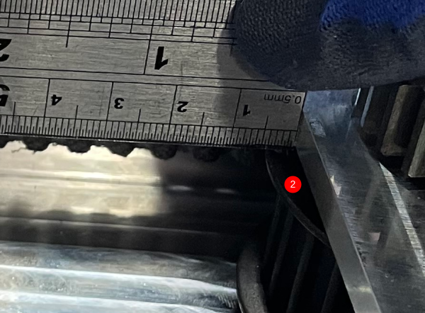
Étape 8 - Couple and align gearbox and pinion assembly
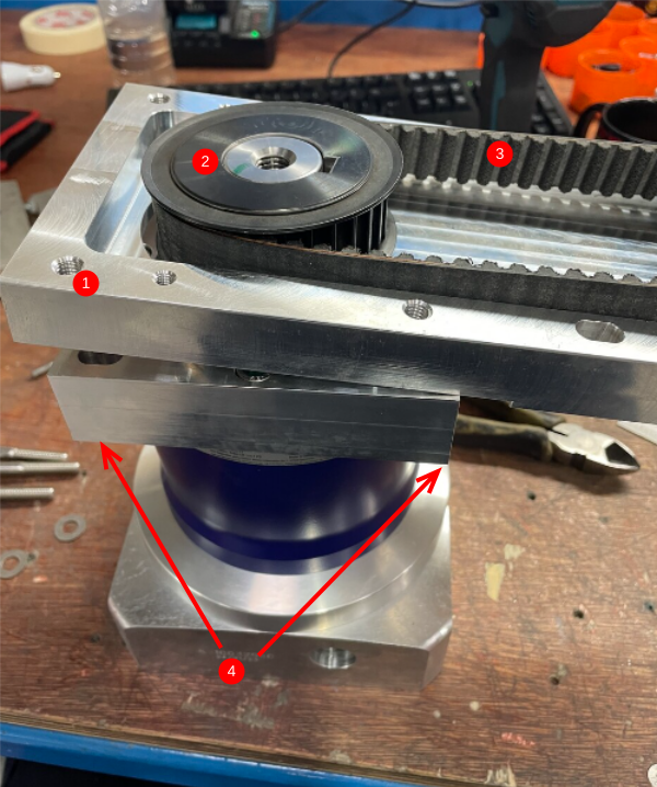
Insert part1 through part 2
Hook over belt (3)
insert 4 off m8 x 50 with a form washers a pull to face lightly
Étape 10 - Remove pulley assembly
Reverse steps to remove assembly 1
Remove part 2
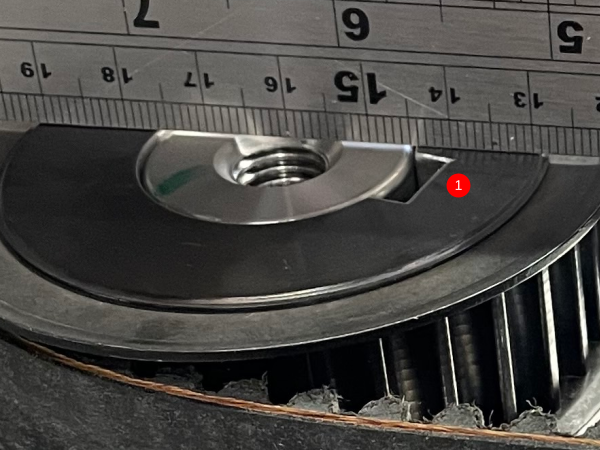
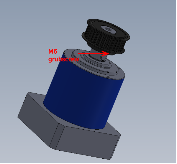
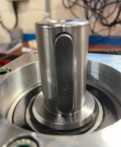
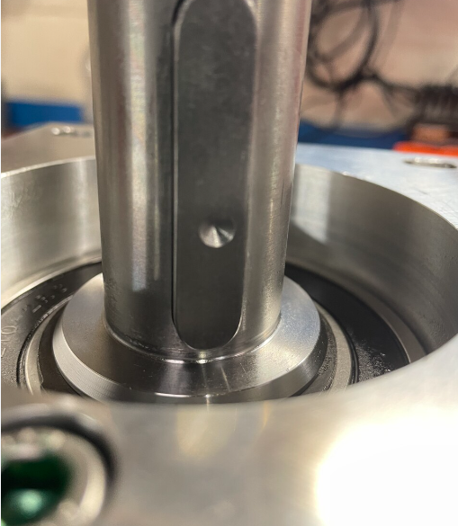
Tighten grubscrew to leave witness mark , Remove pulley and drill 5mm dimple at indicated point
Use M6 x 10 kcp grubscrew to lock pulley in final position
Rebuild parts to get to 3
Étape 11 - Tension belt
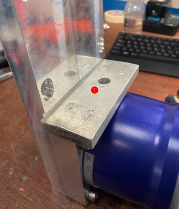
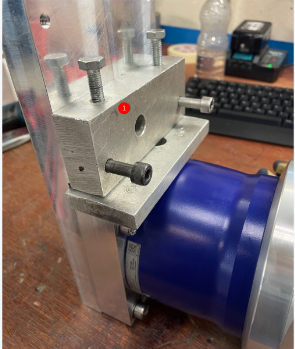
1 Attach tensioning jig as shown
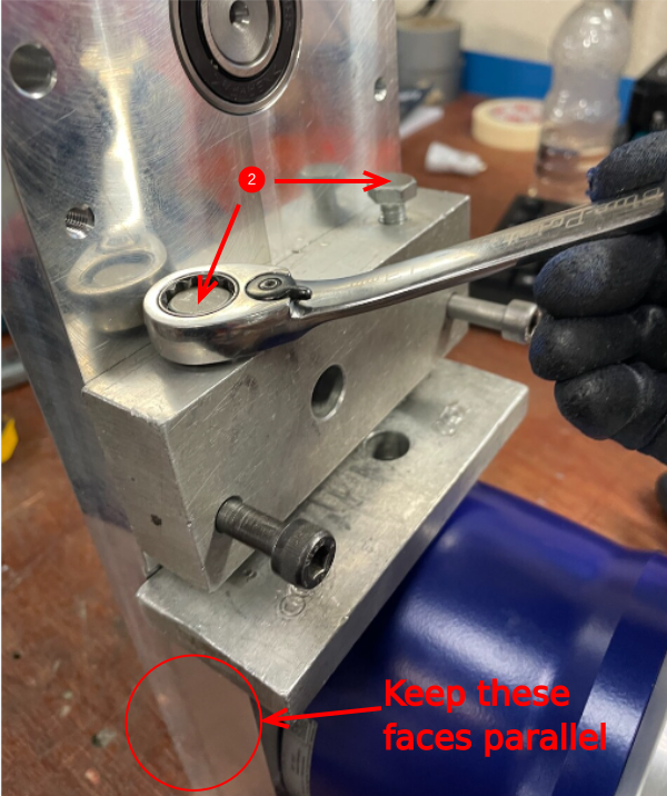
2 Apply tension to belt , spreading tension over two bolts indicated . Maintain parallel on these faces as adjusting
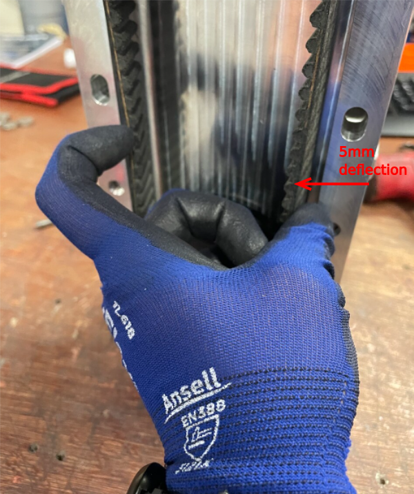
Set belt tension to 5mm deflection (Drum Tight )
Étape 12 - finalise position
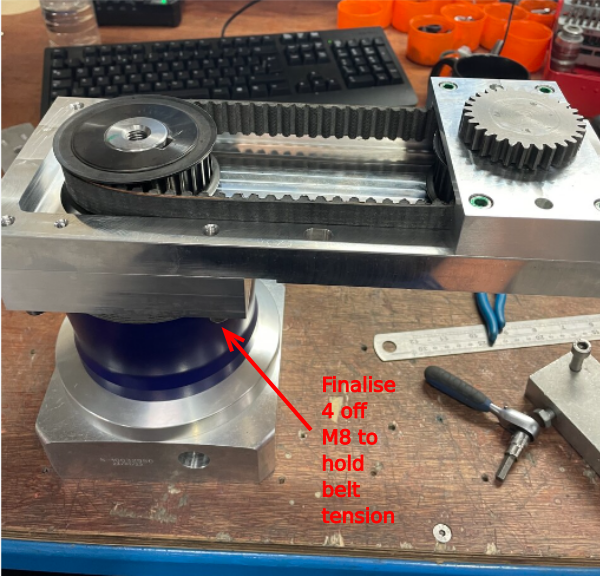
finalise 4 off m8 socket caps to hold tension
Remove setting jig plates
Draft



 Français
 English
 Deutsch
 Español
 Italiano
 Português