Instructions to instal Pneumatic connections onto module
Sommaire
- 1 Introduction
- 2 Étape 1 - Mount Pneumatic rail
- 3 Étape 2 - Install Y244 material load sensor blowers
- 4 Étape 3 - Install Y125 Pop up C pipework
- 5 Étape 4 - Install Y124 Roller beds
- 6 Étape 5 -
- 7 Étape 6 -
- 8 Étape 7 -
- 9 Étape 8 -
- 10 Étape 9 -
- 11 Étape 10 -
- 12 Étape 11 -
- 13 Étape 12 -
- 14 Commentaires
Introduction
Tools Required
Pipe cutters
Number identification
Flush cutters
Parts Required
P0000160 Flow regulator 6mm inline x 2P0000551 6mm inline Quick Exhaust Fitting x 3
P0001008 Regulator: ARG20 0 - 8.5 Bar c/w Gauge x 1
P0001023 Fitting: SMC 6mm mini Y x 4
P0001030 Fitting: SMC 6mm Equal Tee x 27
P0001108 12mm Tee connector x 2
R0015071 Pneumatics railÉtape 1 - Mount Pneumatic rail
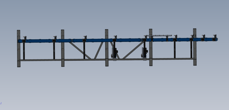
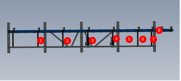
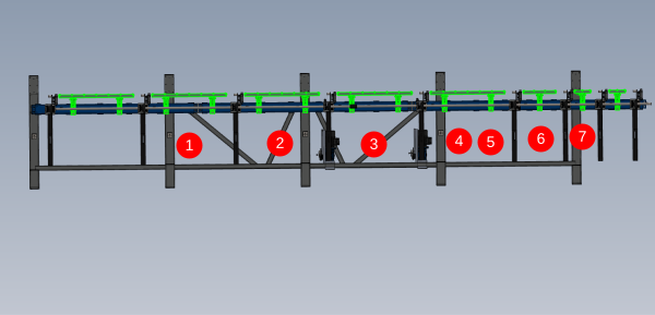
Mount pre assembled pneumatic rail R0015071 into the position shown . Fix with M6 fasteners (size of fasteners and height of rail on frame required)
Étape 2 - Install Y244 material load sensor blowers
6mm Black air pipe
Identify all pipes as 2449
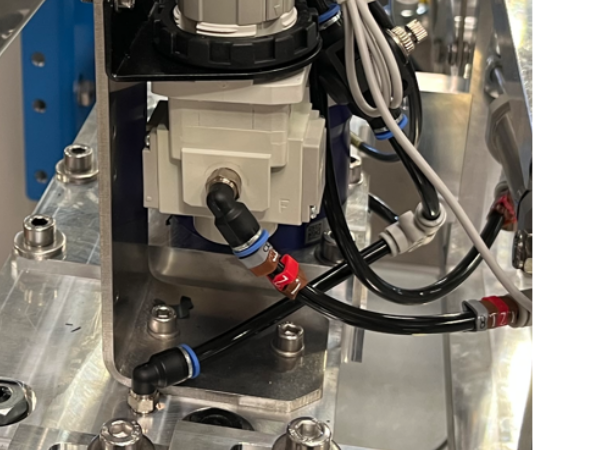
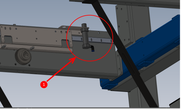
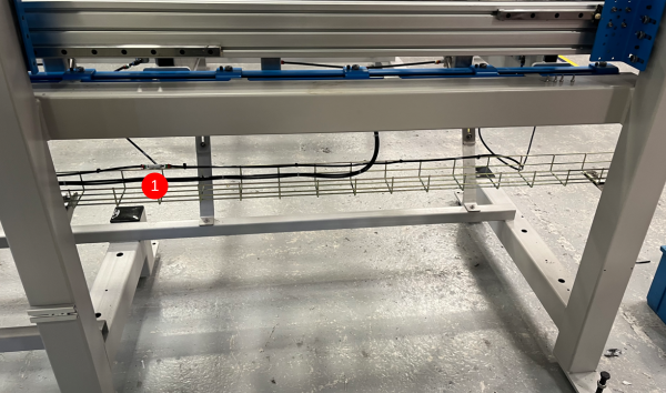
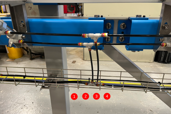
- Connect 2 off pipes to fitted P0000200 elbows (1) and add P0001023 mini y connector to pipes to convert to single feed pipe
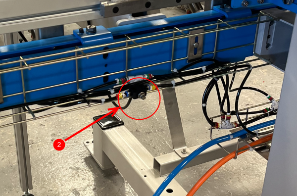
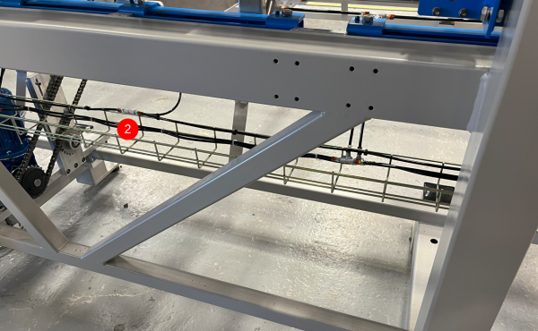
- attach long enough pipe to reach wire basket directly behind (2) . Ensure slack is left to allow for roller movement up
- Add P0000160 Flow regulator
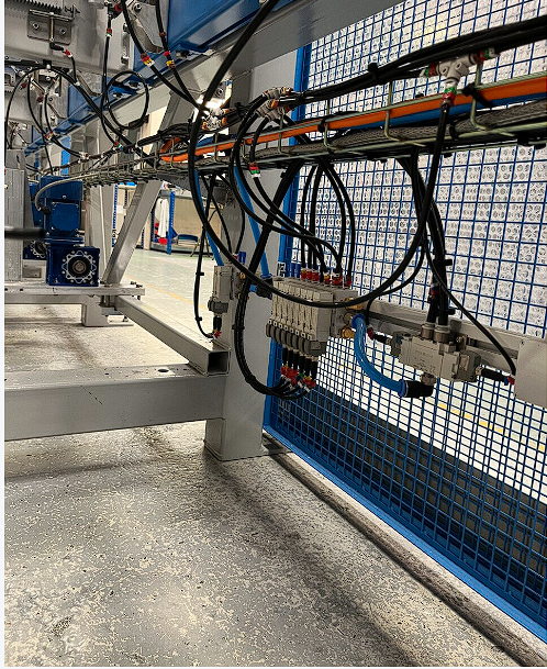
- Add pipe to flow regulator fitting to reach main valve bank
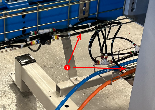
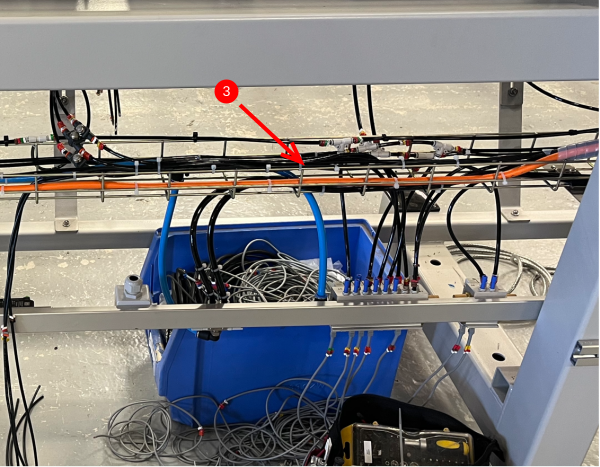
- Attach to indicated sections (3) of wire basket
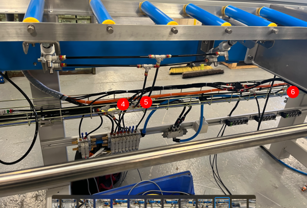
- Connect to (4 -active) port of valve slice
Étape 3 - Install Y125 Pop up C pipework
6mm black air pipe
Pipe identified as 1259
9 off pop up C cylinders to be connected (1)
Ensure enough slack is left on pipe between basket and cylinder to allow full range of movement
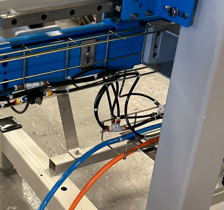
- (1) 6mm tee feeds cylinder above and to the left
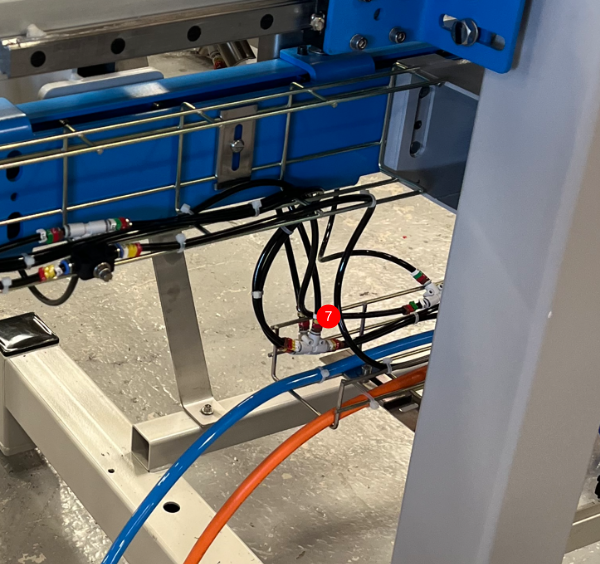
- (2) 6mm tee feeds cylinder above and ring main left and right
- (3) 6mm tee feeds cylinder above and ring main left and right
- (4) 6mm tee feeds cylinder above and ring main left and right
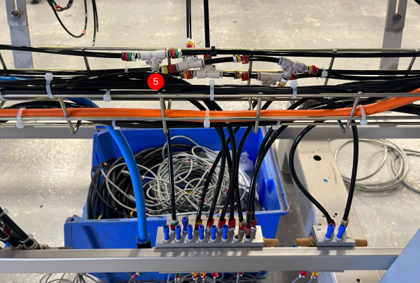
- (5) 6mm tee feeds valve below and ring main left and right
- (6) 6mm tee feeds cylinder above and ring main left and right
- (7) 6mm tee feeds cylinder above and ring main left and right
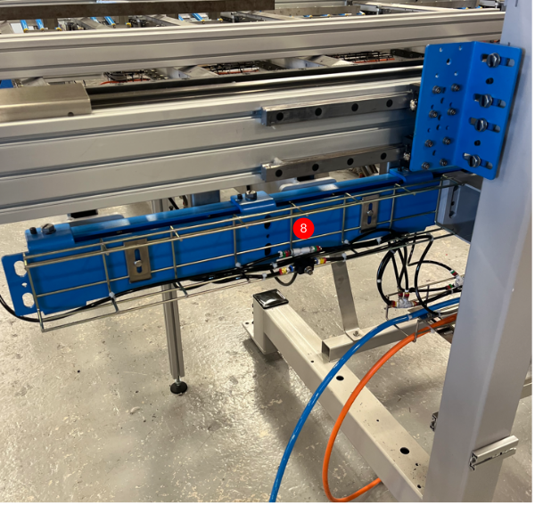
- (8) 6mm tee feeds cylinder above and cylinder to the right
Étape 4 - Install Y124 Roller beds
6mm black air pipe
Pipes identified as 1249 and 1241
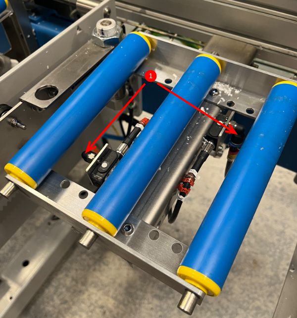
Cylinder nose 1249
Cylinder base 1241
(1) (2) (3) (4) connect all as shown using 6mm tee fittings position (1) feeds roller to the left as well as one above
(4) Feeds ring main to valve
(5) Feeds cylinder above and ring main to the right
(6) Feeds cylinder above and ring main to the right
(7) Feeds cylinder above and cylinder to the right
Étape 5 -
Étape 6 -
Étape 7 -
Étape 8 -
Étape 9 -
Étape 10 -
Étape 11 -
Étape 12 -
Draft
 Français
 English
 Deutsch
 Español
 Italiano
 Português