Instructions to pneumatically test build module

Difficulté
Moyen
Durée
2 heure(s)
Sommaire
- 1 Introduction
- 2 Étape 1 - Health and Safety
- 3 Étape 2 - Check all connections are made
- 4 Étape 3 - Connect air feed
- 5 Étape 4 - check for air leaks
- 6 Étape 5 - Check home positions
- 7 Étape 6 - Test valve bank outputs
- 8 Étape 7 -
- 9 Étape 8 -
- 10 Étape 9 -
- 11 Étape 10 -
- 12 Étape 11 -
- 13 Étape 12 -
- 14 Commentaires
Introduction
Tools required
Pcl air line -12mm connector
Parts Required
Étape 1 - Health and Safety
In this process pneumatic outputs will be tested in a non emergency stop environment
Ensure safe working practice is followed
- Ensure Machine test area is clear from personnel and all staff are aware of testing procedure commencing
- Ensure all Air connection lines are connected
- Ensure all walkways are not impeded by trailing pipes/leads
- Ensure all mechanical assemblies are at a sufficient stage for testing

Étape 2 - Check all connections are made
- Check all valve bank ports are either connected or blanked off
- Check all mains feed pipes are connected or isolated
- Check all regulators are regulated to minimum setting
- Check all air flow control valves on cylinders and blow lines are set to mid range adjustment
Étape 3 - Connect air feed
Connect air feed to mains 12mm feed pipe using pcl coupling and 12mmm push fit adapter
Étape 4 - check for air leaks
Investigate any air leaks and resolve
Étape 5 - Check home positions
With no valves active ( no over rides pressed ) the following home positions of pneumatic assemblies should be
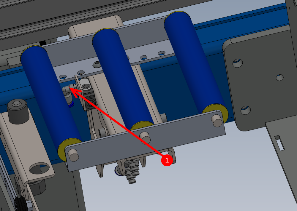
1 Y244 material load sensor blowers should be switched OFF
2 Y125 Pop up C should be retracted
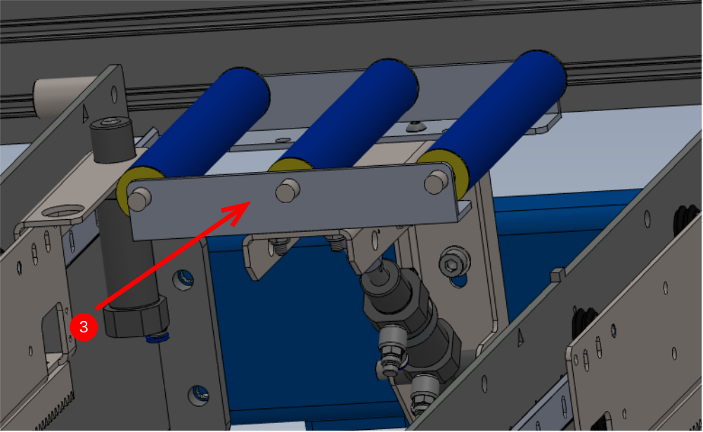
3 Y124 Roller beds should be lifted
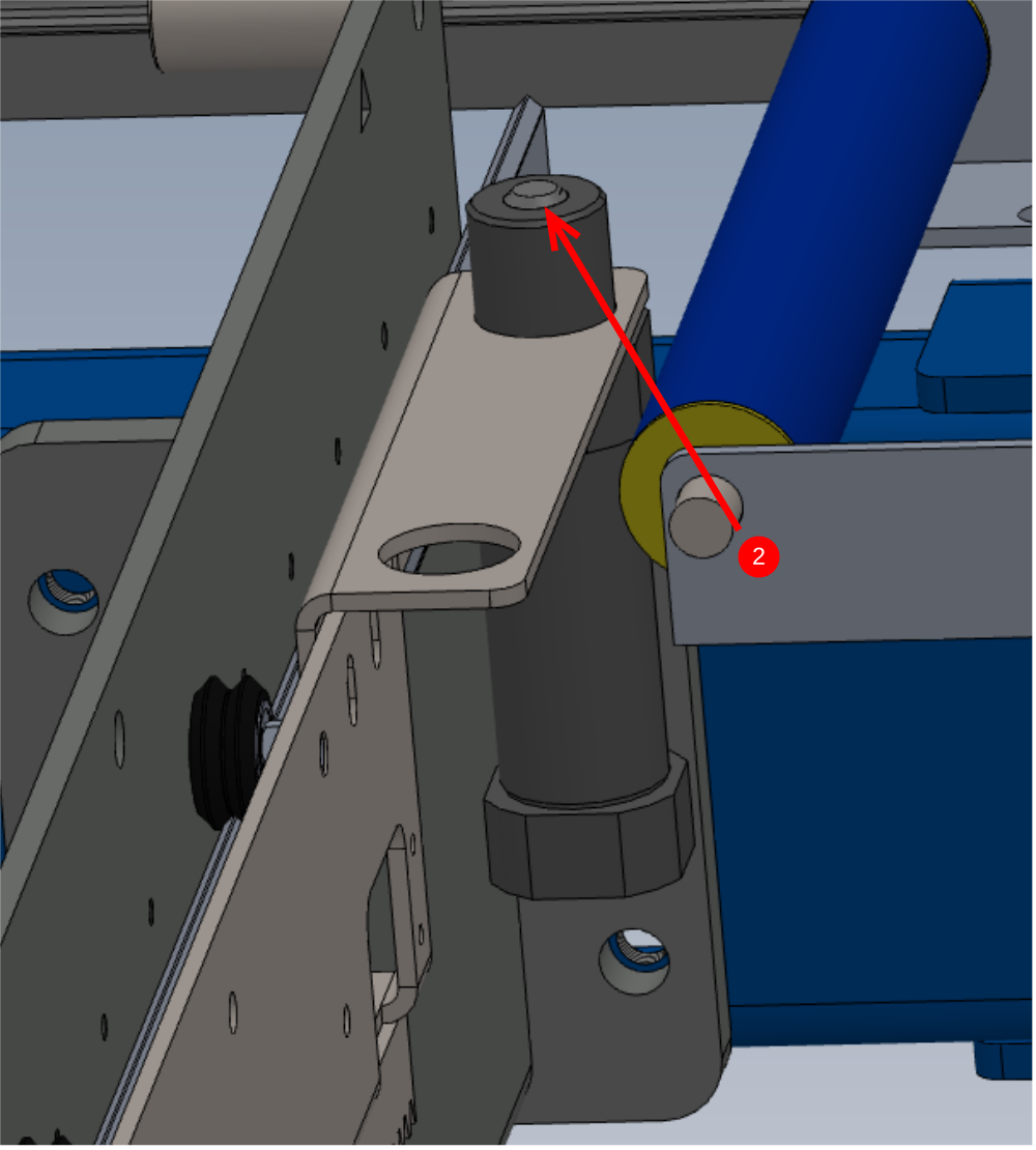
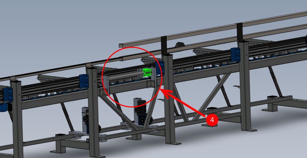
4 Y126/Y127 Beam position should be closest to extraction end
5 Y122 Rack blower ashould be switched OFF
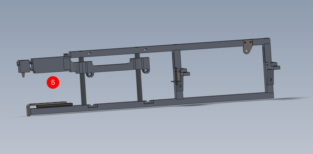
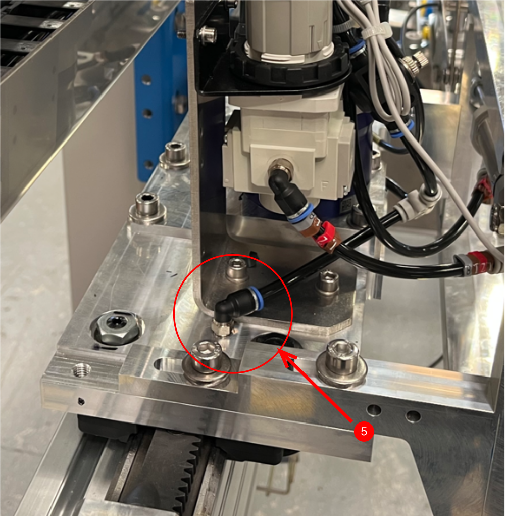
6 Y121 Gripper height should be raised up
Any discrepancies on these should be investigated to correct
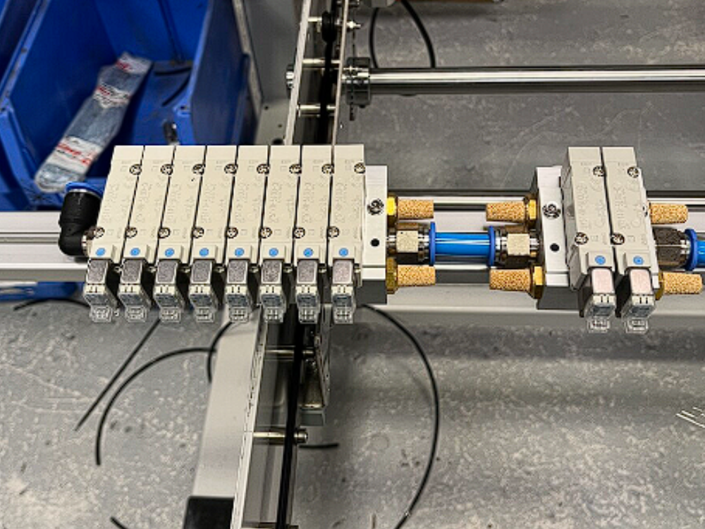
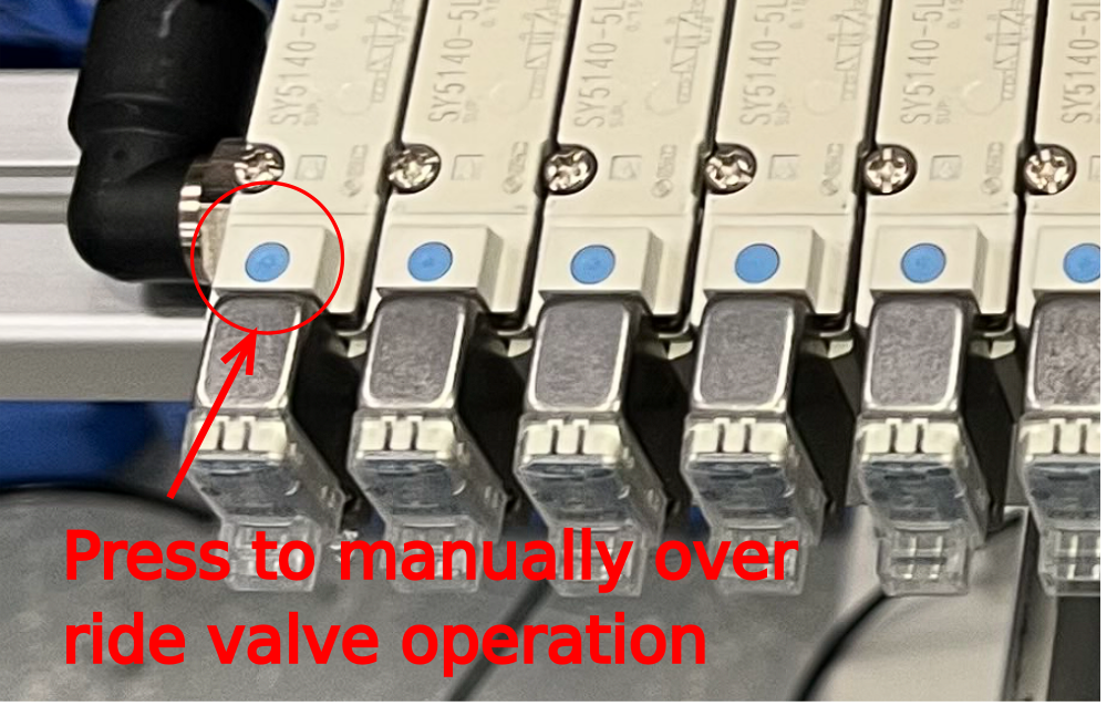
Étape 6 - Test valve bank outputs
Each valve on the Valve bank can be manually overridden to activate the output.
Étape 7 -
Étape 8 -
Étape 9 -
Étape 10 -
Étape 11 -
Étape 12 -
Draft
 Français
 English
 Deutsch
 Español
 Italiano
 Português