Instructions for bench assembling infeed arms

Difficulté
Moyen
Durée
6 heure(s)
Sommaire
- 1 Introduction
- 2 Étape 1 - Unless otherwise stated
- 3 Étape 2 - Prepare main arm for assembly
- 4 Étape 3 - Attach runner strips and chain guide
- 5 Étape 4 - Add Location Spiral pin
- 6 Étape 5 - Assemble chain tensioner pinion
- 7 Étape 6 - Assemble slide unit
- 8 Étape 7 - Attach tensioner pinion
- 9 Étape 8 - Mount to loading arm
- 10 Étape 9 - Assembly support bars
- 11 Commentaires
Introduction
Tools Required
Circlip pliers internal and external
Standard hex key set
Standard spanner set
Standard Tap set
Parts Required
D0015456B x 9
D0001256 x 9
D0002943 x 9
D0001254 x 9
D0001253 x 9
D0002717 x 18
D0001255 x 9
H0007576 x 9
B0000252 x 9
D0007577 x 9
D0002999 x 9
D0015619 x 9
D0015620 x 9
Étape 1 - Unless otherwise stated
Use loctite 243 on all fasteners
Pen mark all fasteners once finalised

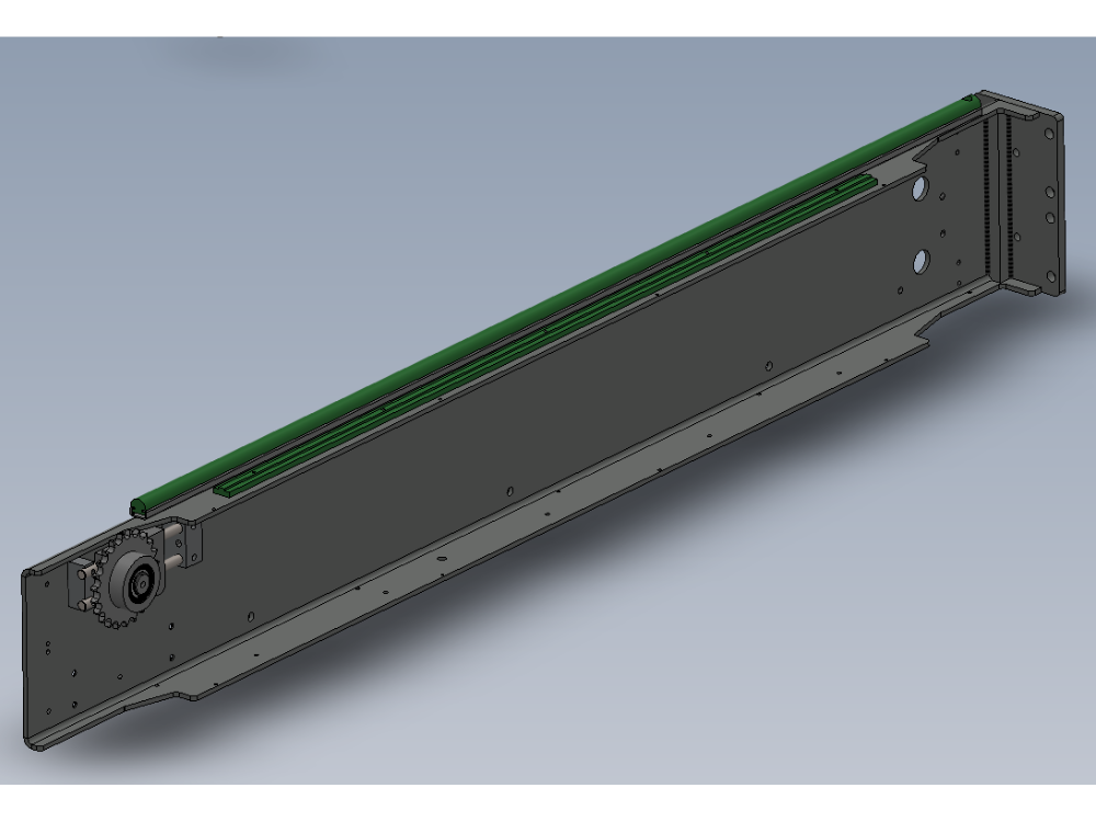
Étape 2 - Prepare main arm for assembly
9 off
D0015456B load arm needs preparing before assembly.
All tapped holes require contaminants removing before assembly. Use appropriate taps to clean all threads on load arms

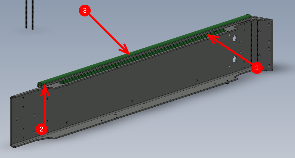
Étape 3 - Attach runner strips and chain guide
9 off
1 Attach chain guide D0001256 as shown using 5 off M4 x 12 socket caps
2 Attach lower channel D0002943 as shown using M5 x 10 button heads
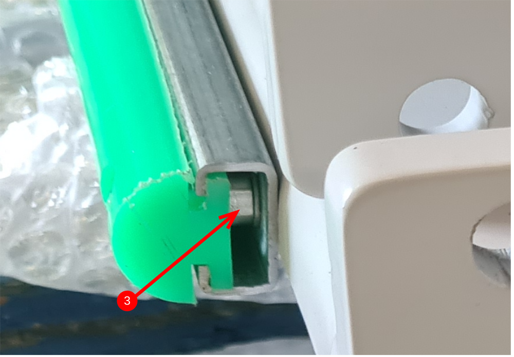
3 Slide plastic guide into channel and fix with M5 x 12 socket cap and A form washer
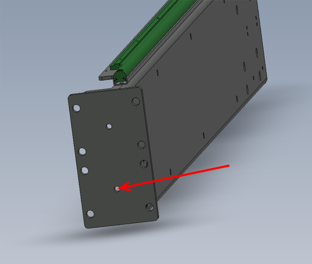
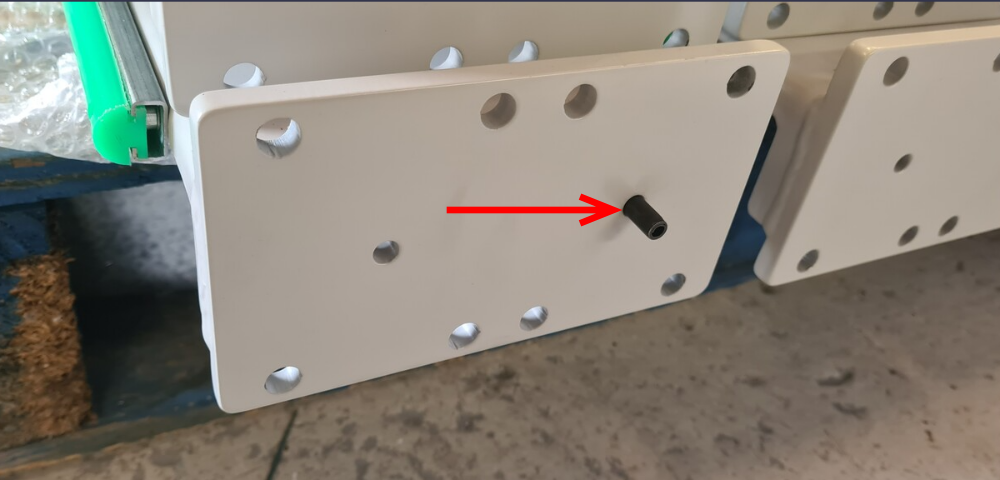
Étape 4 - Add Location Spiral pin
9 off
Add 8mm x 24mm spirol pin to indicated hole
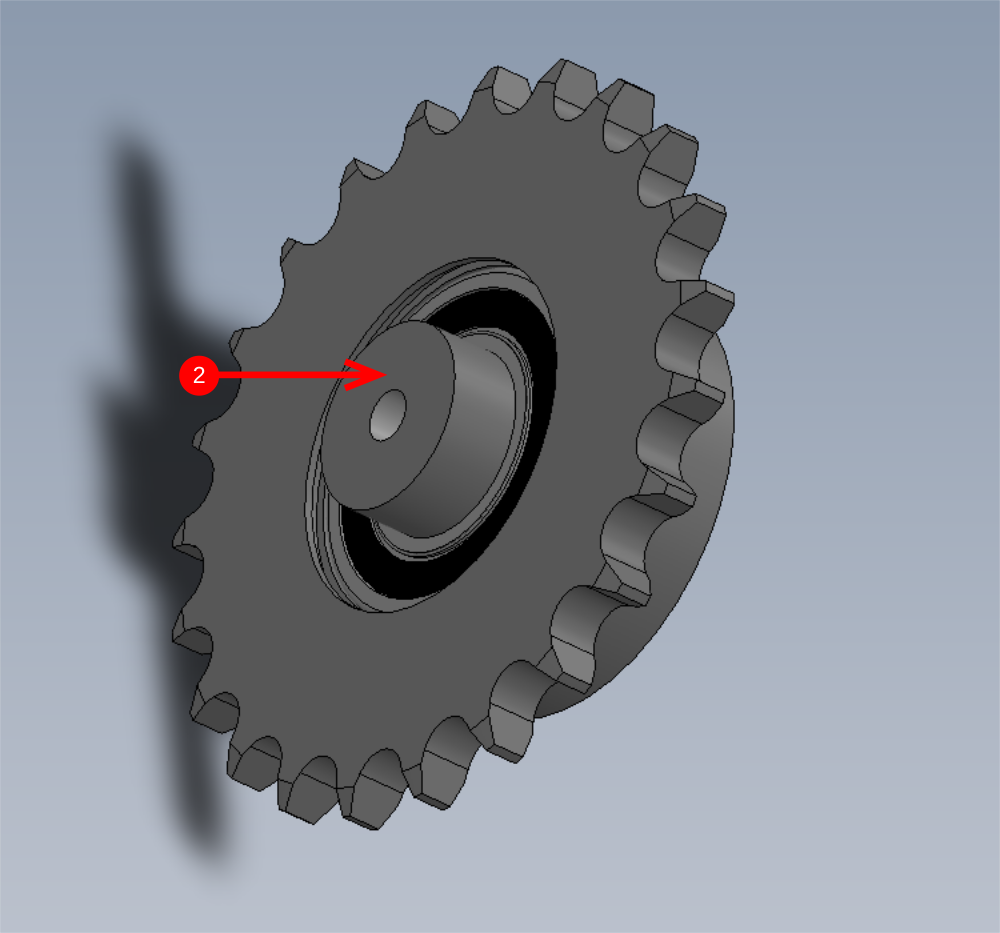
Étape 5 - Assemble chain tensioner pinion
9 off
1 Use press to fit bearing B0000252 to idler pinion D0007576. Ensure bearing fit is correct. If bearing is loose, degrease with FE10 solvent and use bearing fit to secure bearing . If bearing is tight, measure bore and report via NCR system if out of tolerance . Retain bearing with 47mm internal circlip
2 use press to insert D0007577 into bearing as shown. Ensure fit is correct. Use FE10 solvent and bearing fit if loose, if tight measure and inspect and report through NCR system. Fix in place with a 20mm external circlip

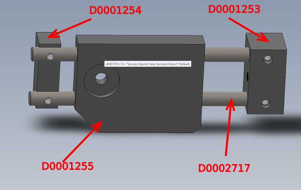
Étape 6 - Assemble slide unit
9 off
Assemble as shown the following with no fixings
D0001255
D0002717
D0001253
D0001254
Ensure D0001255 slides along shafts once assembled
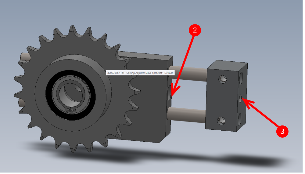
Étape 7 - Attach tensioner pinion
9 off
1 Attach tensioner pinion to assembly using M8 x 35 socket cap and M8 motorplate washer
2 Add D0002999 jacking insert into block
3 Add M8 x 100 set bolt and M8 nut to the indicated face

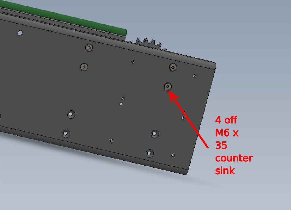
Étape 8 - Mount to loading arm
9 off
Use 4 off M6 x 35 countersink bolts to attach tensioner assembly to loading arm

Étape 9 - Assembly support bars
9 off
Combine as shown D0015619 and D0015620 using M8 x 30 socket caps, M8 heavy washers and M8 nyloc nuts
Orientate as shown in picture

Draft
 Français
 English
 Deutsch
 Español
 Italiano
 Português