Instructions to mount and set X axis gearbox and motor drive parts

Difficulté
Moyen
Durée
1.5 heure(s)
Sommaire
- 1 Introduction
- 2 Étape 1 - Unless otherwise stated
- 3 Étape 2 - Check drive
- 4 Étape 3 - Attach Gearbox mount plate
- 5 Étape 4 - Fit pinion
- 6 Étape 5 - Mount to carriage plate
- 7 Étape 6 - Set drive pinion height
- 8 Étape 7 - Set Gear meshing
- 9 Étape 8 - Check back lash between gears
- 10 Étape 9 - Identify torque setting
- 11 Étape 10 - Fit servo motor
- 12 Étape 11 - Apply torque
- 13 Étape 12 - Add end stops to main drivebeam
- 14 Commentaires
Introduction
Tools Required
Feeler gauge set
Standard hex key set
Standard Tap set
Torque wrench (0-50nm)
Extended 4mm hex bit 1/8 drive
Parts Require
D0015073B x 1
C0001212 x 1
H0008301 x 1
C0001122K x 1
D0015290 x 2
M0001087 x 2Étape 1 - Unless otherwise stated
Use loctite 243 on all fasteners
Use Loctite 572 on all threaded pneumatic connections
Pen mark all fasteners to show finalised

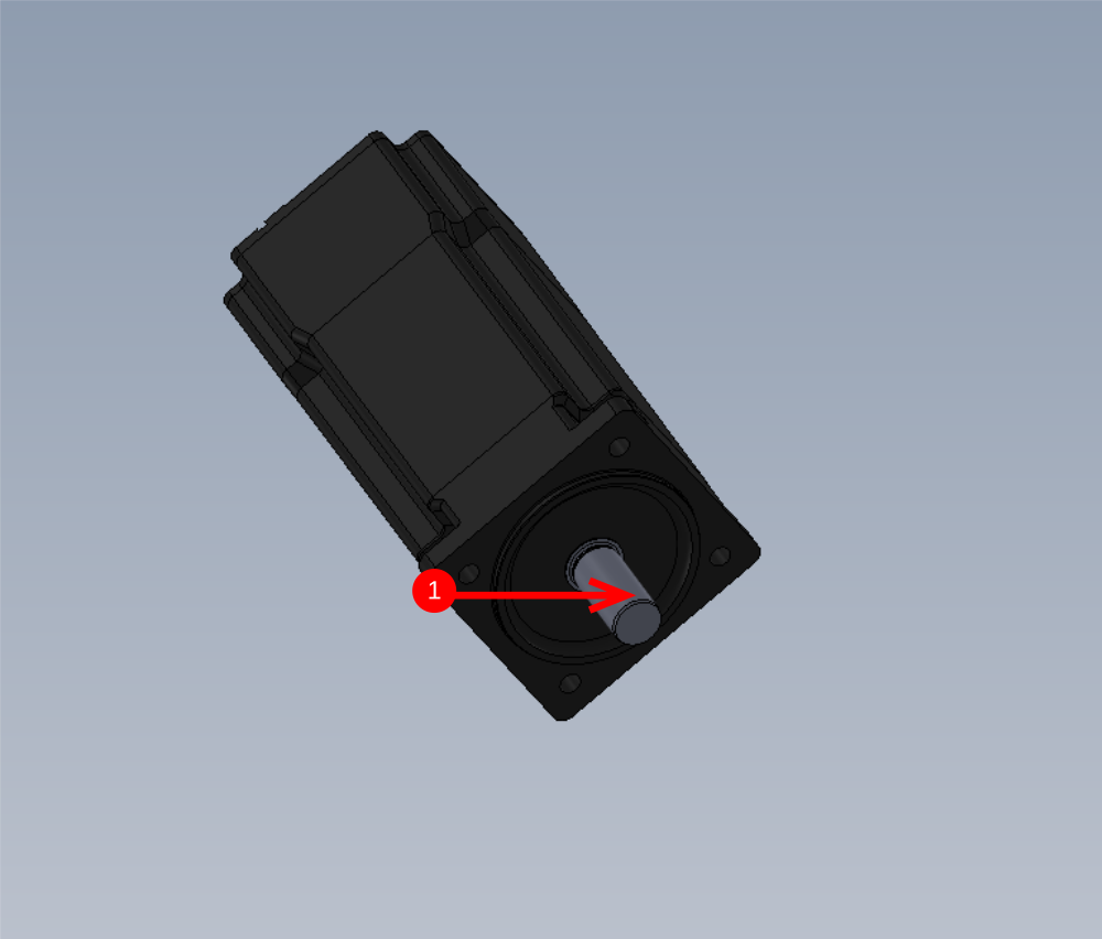
Étape 2 - Check drive
Check fit of drive pinion H0008301 onto gearbox C0001212 . Pinion should be able to move over shaft and key, as adjustment will be required later

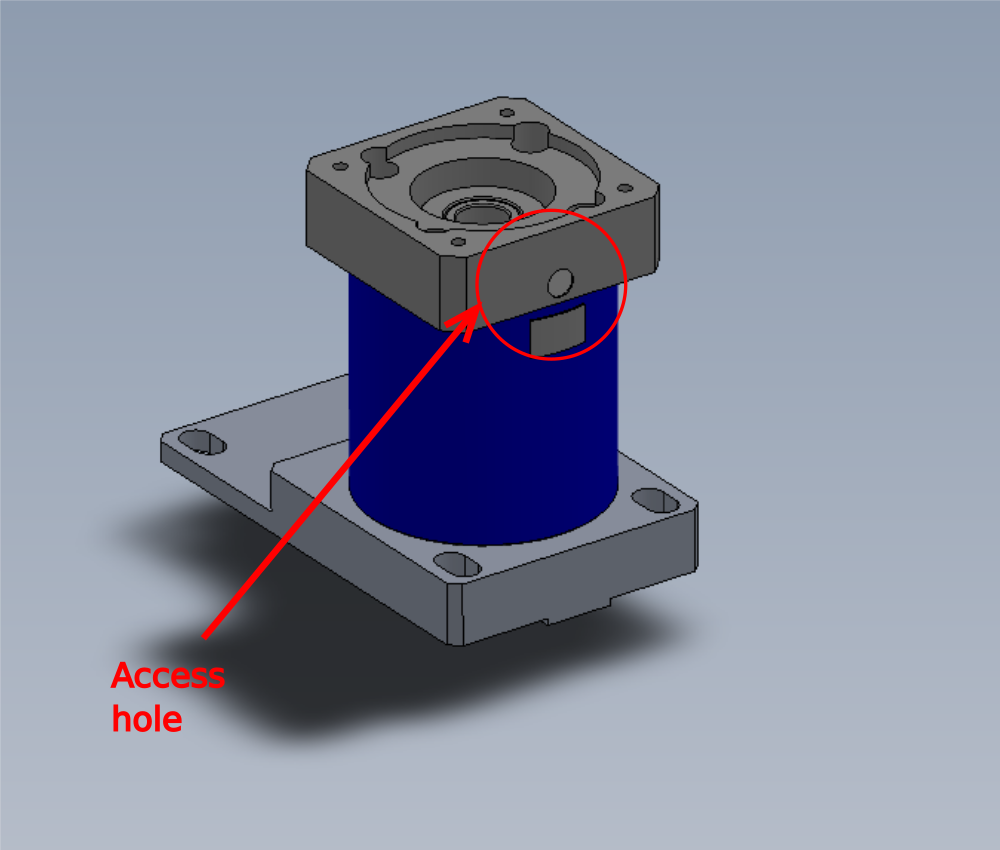
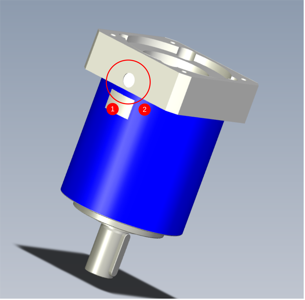
Étape 3 - Attach Gearbox mount plate
Attach gearbox mount plate D0015073B as shown to gearbox C0001212
Use 4 off M5 x 25? socket cap to fix
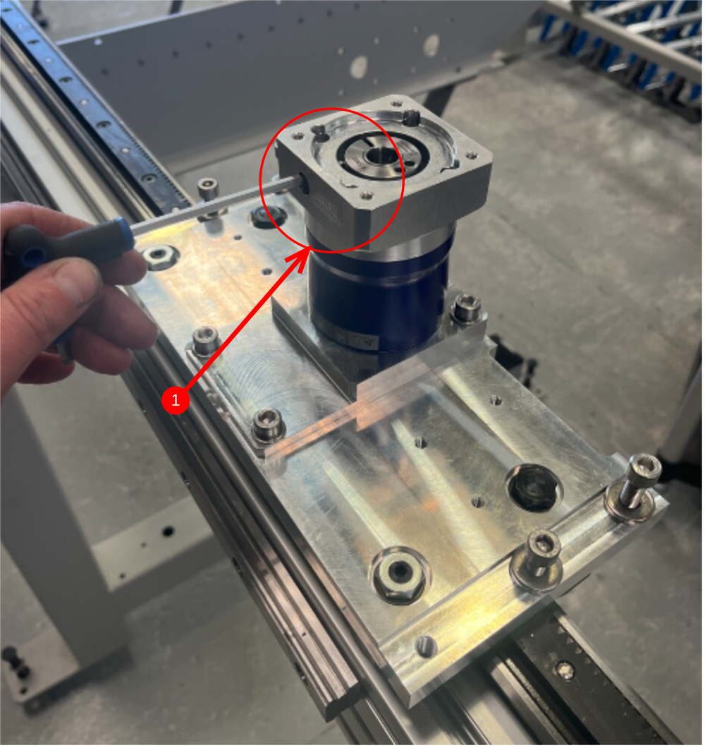
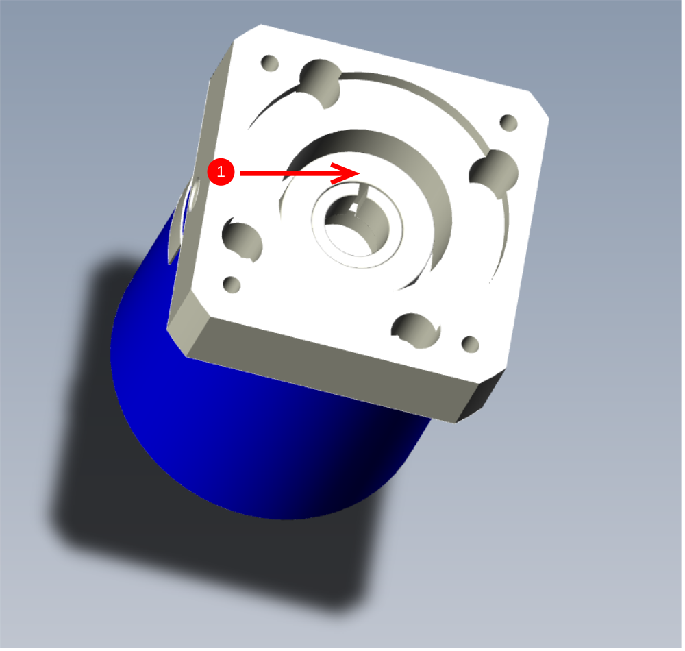
Ensure orientation is as shown and gearbox access hole is in the correct position

Étape 4 - Fit pinion
Attach pinion to gearbox but do not secure

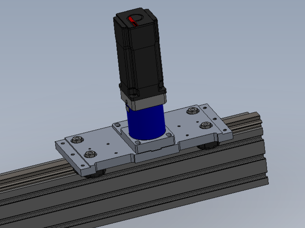
Étape 5 - Mount to carriage plate
Mount to carriage plate as shown using 2 off M8 x 35 socket cap and heavy M8 washer and 2 off M8 x 25 socket cap with heavy M8 washer. Do not apply adhesive at this point and lightly tension fasteners

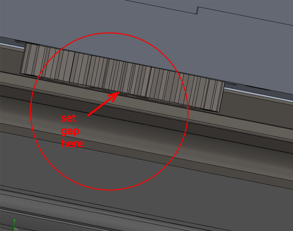
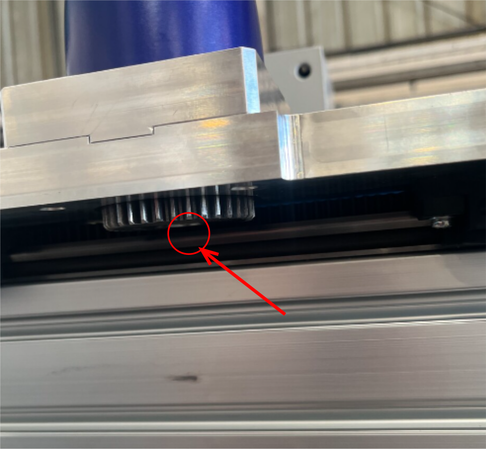
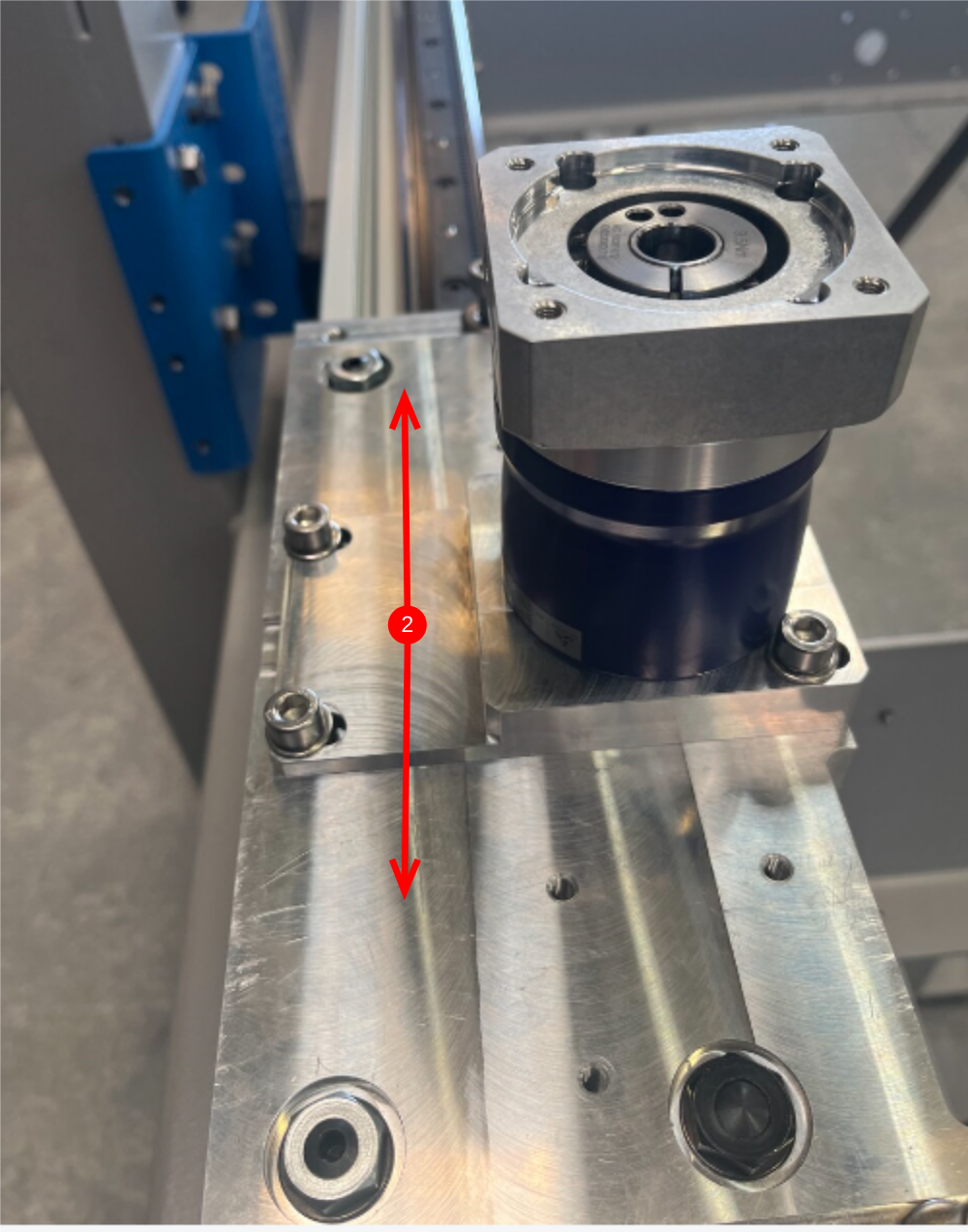
Étape 6 - Set drive pinion height
Set height of drive pinion in relation to hepco rail V edge .
Gap between these parts should be 0.25mm (0.010")
To set this use feeler gauge
Fix pinion in position with M6 x 10 KCP grubscrew
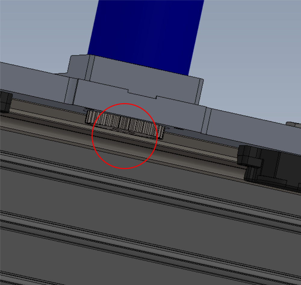
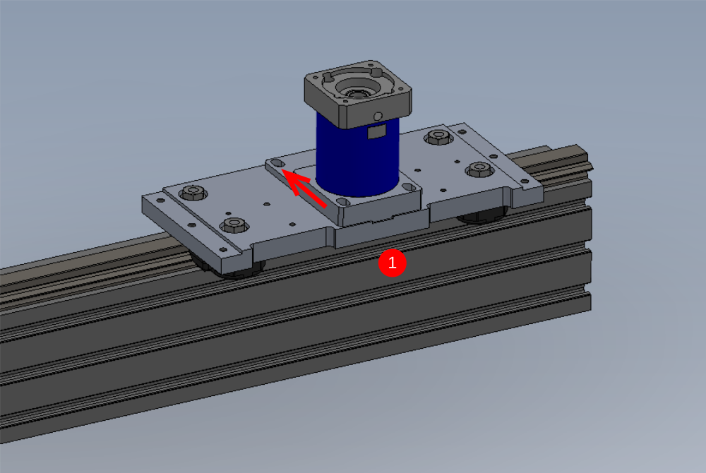
Étape 7 - Set Gear meshing
The gear meshing will need to be set to the least possible backlash that the v rail will allow , with no over over meshing . To set this the following needs to be done
Start at end of main hepco rail
1 Release tension on gearbox mounting plate fasteners and push in direction shown to put gearbox drive pinion and toothed rail into full mesh . This should only require light finger pressure. Lightly tension 2 off bolts
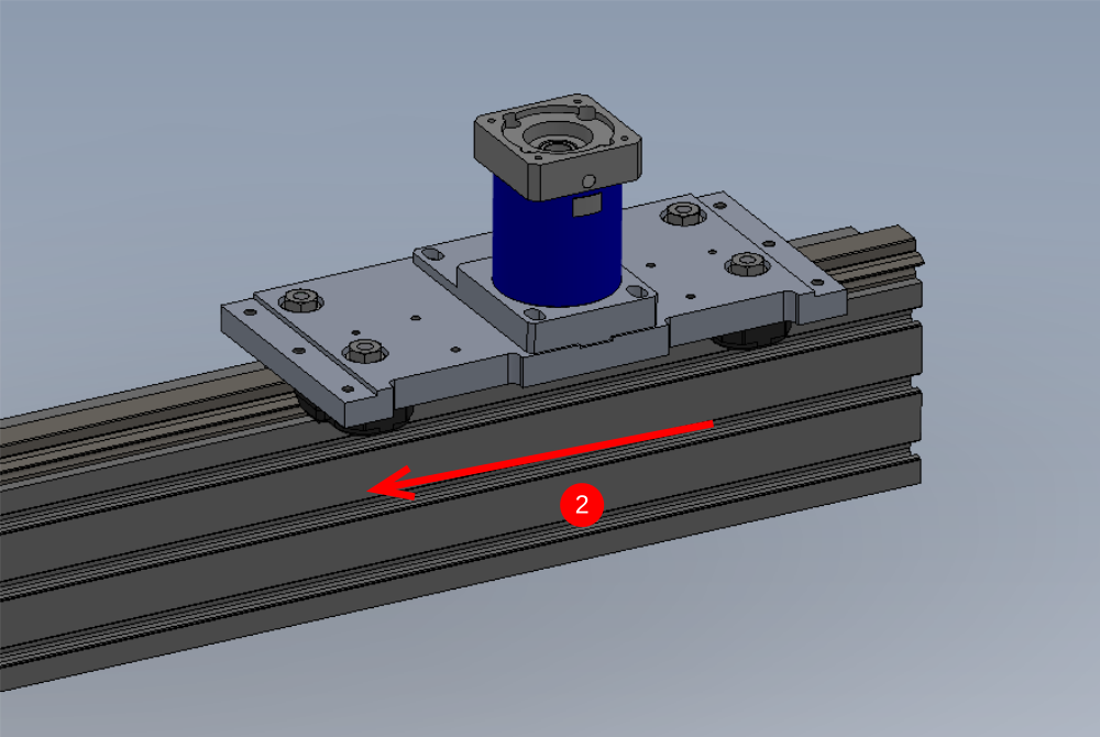
2 Start to push by hand the complete assembly slowly along the hepco rail in the direction shown . Movement should be smooth and consistent.
High spots on the toothed rail need to be identified , and these will be felt when moving the carriage along the rail , as the pressure required to move will increase. . When the high spot is felt, stop the carriage at the exact position and reset to the gearbox assembly as in step 1, to set the back lash to zero at the newly identified high spot
3 Continue these steps until the end of the rail is reached
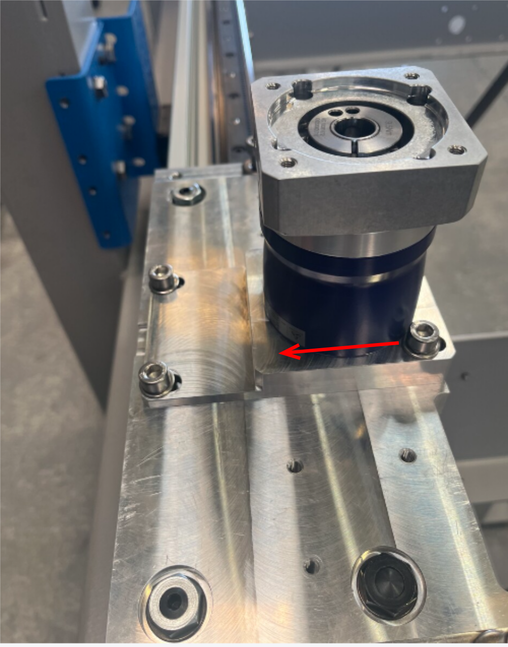
Étape 8 - Check back lash between gears
This can be checked by the following
1 Insert hex key into locking fastener as shown and apply sideways pressure to stop the collar rotating
2 Rock the carriage in the directions shown to see how much movement is present with the gearbox 'locked' Movement in this direction should be minimal to none .
3 Repeat this check at several points along the rail to quantify maximum backlash present. Any excessive backlash should be reported to supervisor
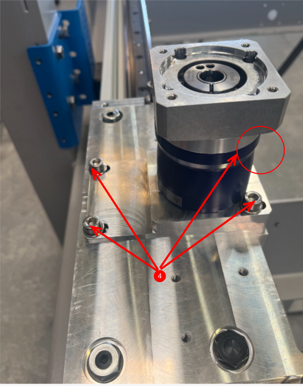
4 Add Loctite 243 to 4 off M8 bolts 1 at a time now positioning is complete
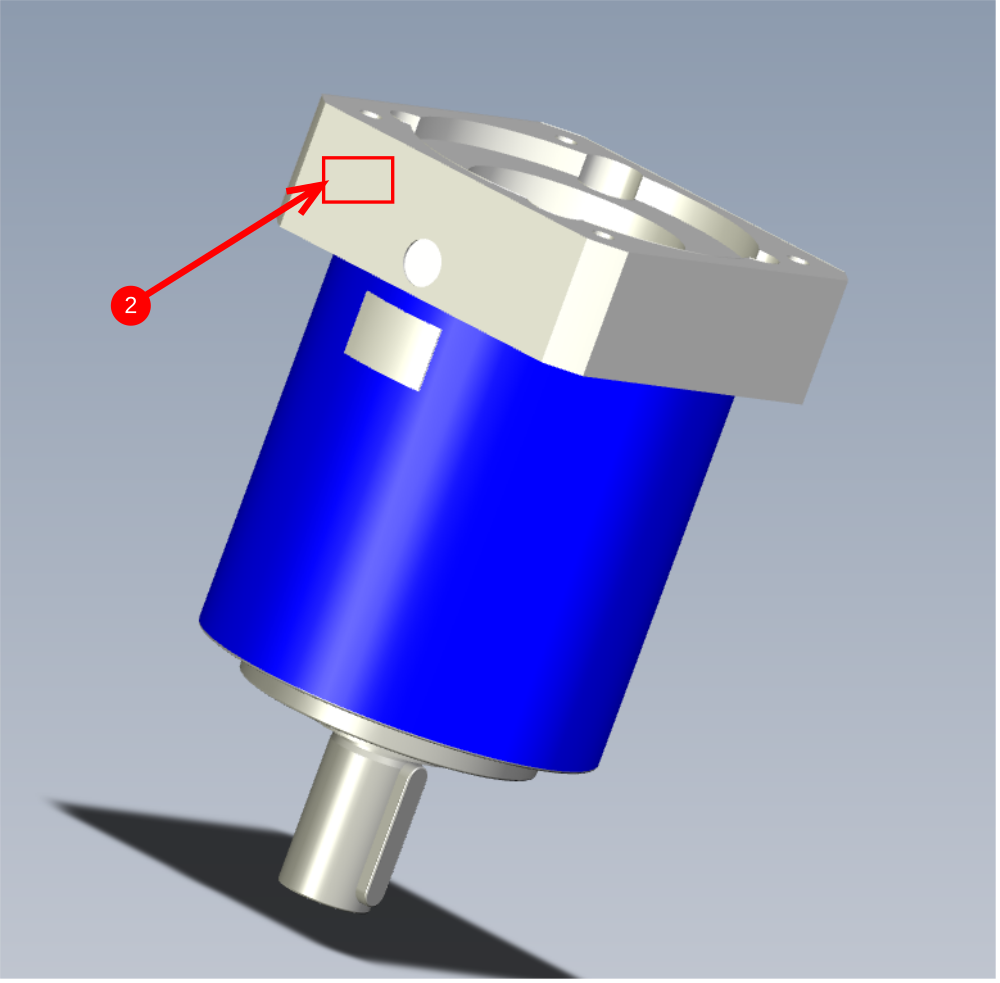
Étape 9 - Identify torque setting
1 Inspect indicated face of gearbox and identify Torque setting for gearbox coupling
2 Transfer this data to beside the access hole to allow setting to be known after servo motor has been fitted
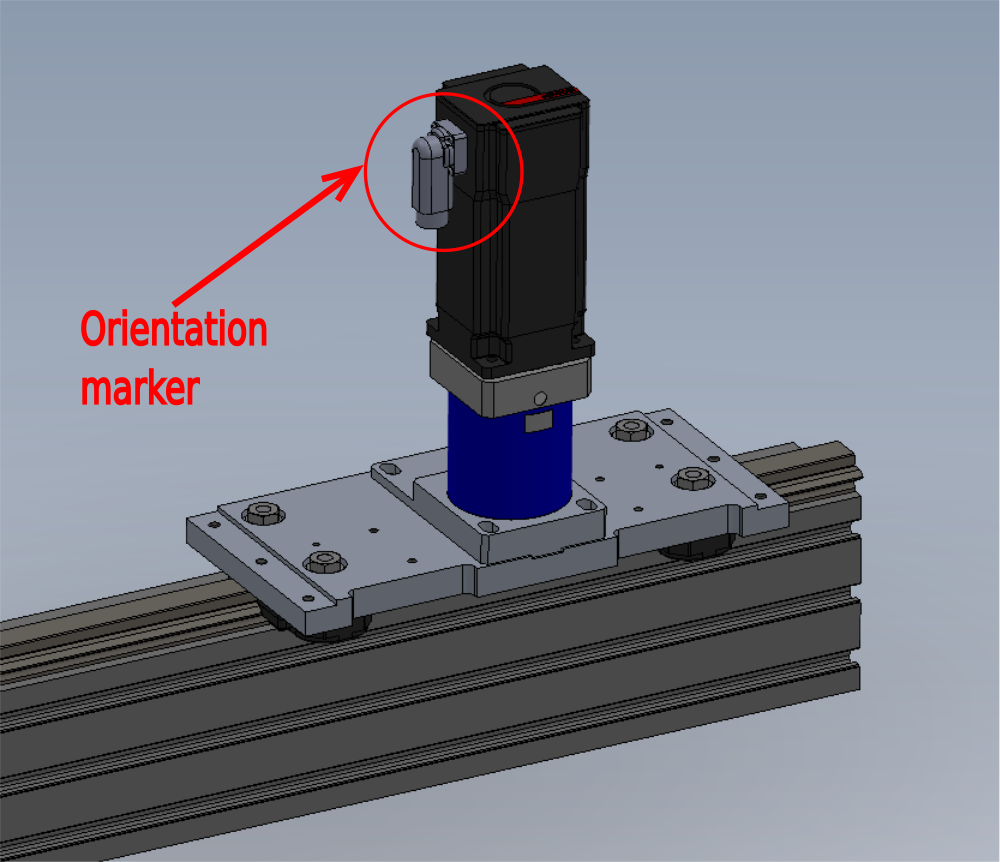
Étape 10 - Fit servo motor
1 Servo motor c0001122k will need degreasing before fitting . The spindle of the motor needs ALL grease removing with FE10 solvent before fitting to the gearbox. This is due to the coupling requiring friction to maintain a mechanical coupling
2 Fit servo motor to carriage assembly and orientate as shown . Use 4 off M5 x 16 socket caps to fasten.
Étape 11 - Apply torque
1 Use torque wrench and set at gearbox nominated setting, then set tightness of coupling
2 Fit access hole bung supplied with gearbox
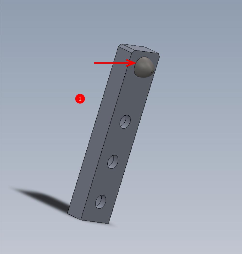
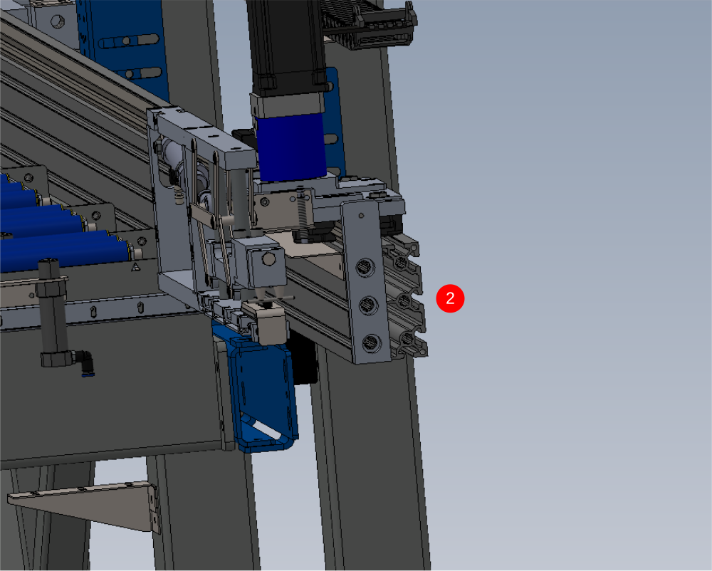
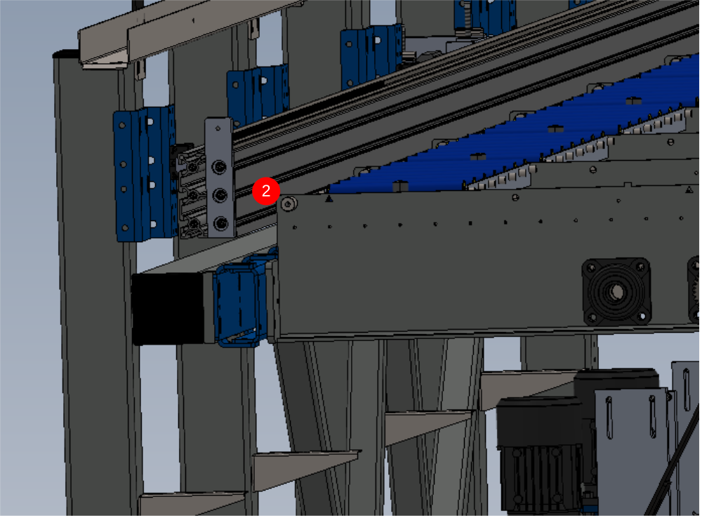
Étape 12 - Add end stops to main drivebeam
1 Attach M0001077 to D0015290 ( 2 off )
2 Use image to identify mounting points on main drive rail and tap relevant holes to M12 x 1.75 pitch (6 off in total)
3 Fix stop brackets as shown with 3 off per stop M12 x 25 socket caps
Draft
 Français
 English
 Deutsch
 Español
 Italiano
 Português