Instructions to assemble loader wheel
Sommaire
- 1 Introduction
- 2 Étape 1 - Unless otherwise stated
- 3 Étape 2 - assemble main base
- 4 Étape 3 - Attach cylinder mount
- 5 Étape 4 - Attach stop block and damper
- 6 Étape 5 - Fit linear bearings and set
- 7 Étape 6 - Grease bearings
- 8 Étape 7 - Fit slide plate
- 9 Étape 8 - Fit motor plate
- 10 Étape 9 - Mount cylinder
- 11 Étape 10 - Add Air fittings
- 12 Étape 11 -
- 13 Étape 12 -
- 14 Étape 13 -
- 15 Commentaires
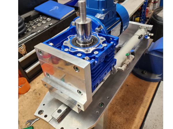
Introduction
Tools Required
Étape 1 - Unless otherwise stated
Use loctite 243 on all fasteners
Pen mark all bolts to show finalised
Étape 2 - assemble main base
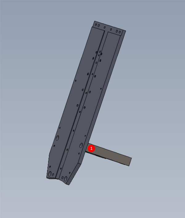
1 Attach D0015438 to D0010431 Using M8 socket caps (size Required )
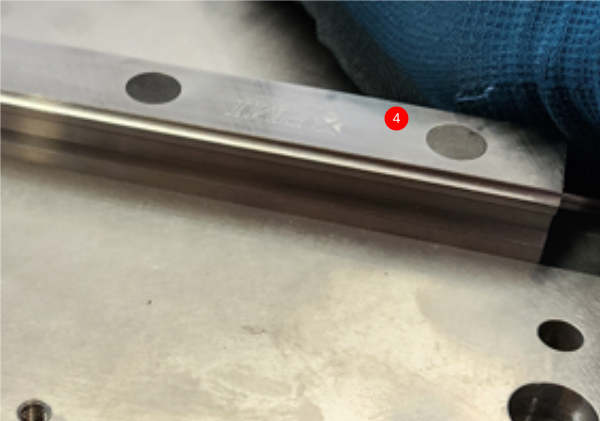
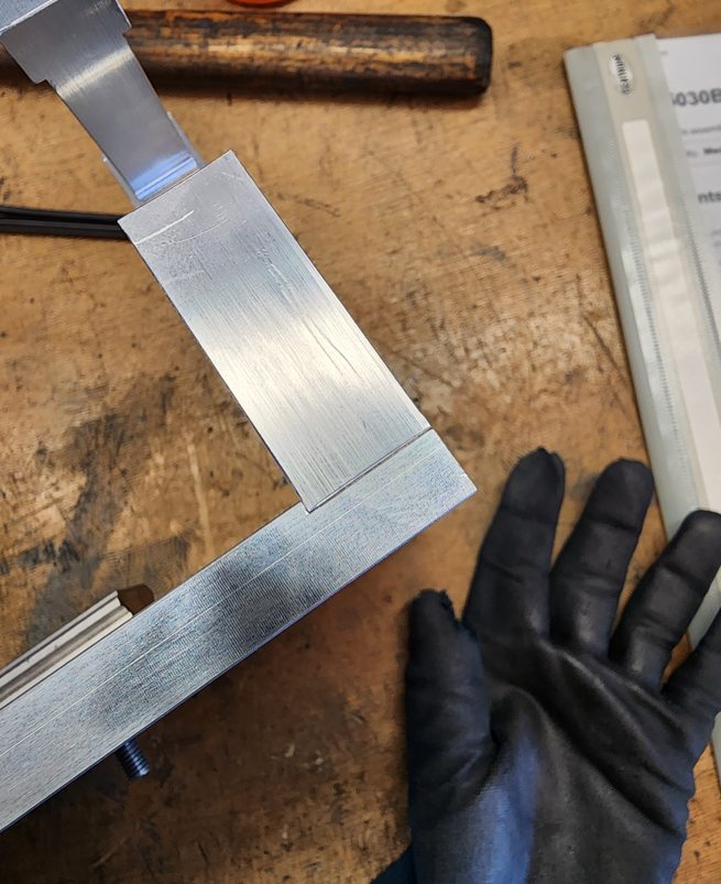
2 Attach linear rail B0000426 using 2 off m6 x 20 socket caps and 5 off M6 x 30 socket caps. Make sure linear rail is pushed hard against one register side of machined slot.
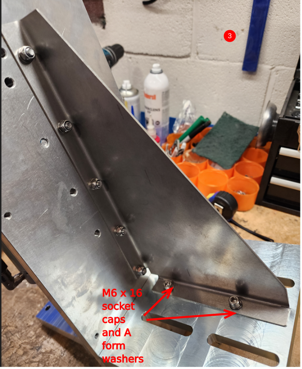
3 Attach D0015741 support web using 5 off M6 nyloc nuts and M6 A form washers and 2 off M6 x 16 socket caps with A form washers
4 Insert rail caps 7 off B0000173 ensuring they sit flush to rail face
Étape 3 - Attach cylinder mount
Attach cylinder mount block D0010238 to assembly with 4 off M6 x 20 socket caps
Étape 4 - Attach stop block and damper
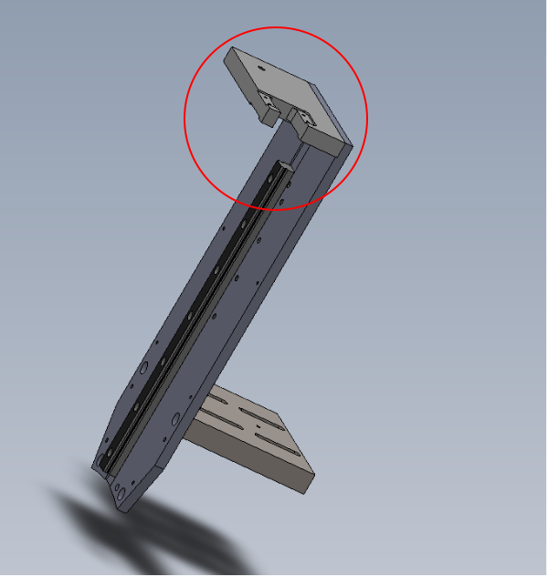
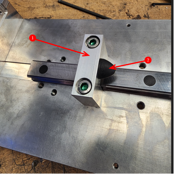
1 Attach damper block D0015439 to main plate in position shown using 2 off M8 x 50 socket caps
2 Attach M0001077 damper to block
Étape 5 - Fit linear bearings and set
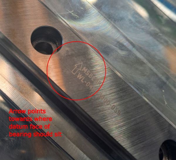
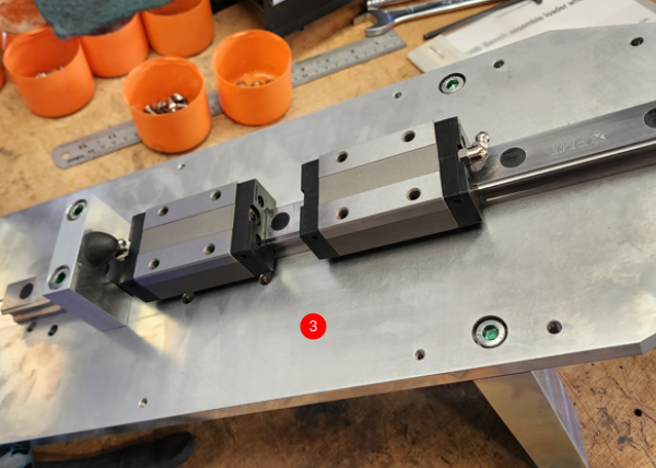
1 Slide B0000046 bearings onto linear rail and ensure datum face of both bearings is facing the same way as the datum arrow on the linear rail. Release m3 button heads (4 off per bearing) the allow seals to centralise to the rail. Retension m3 buttons and then remove bearings from rail.
2 Use Fe 10 solvent cleaner to degrease M6 holes in bearings for correct adhesive function, and then clean with compressed air .
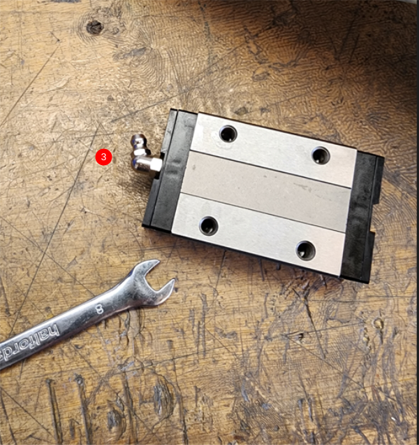
3 fit grease nipples in the orientation shown and then refit bearings to linear rail
Étape 6 - Grease bearings
Use grease gun to grease 2 off B0000046 bearings
Étape 7 - Fit slide plate
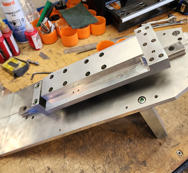
Use 8 off M6 x 12 socket caps to mount D0010509 slide block to bearings , ensuring datum face of bearing pushes up against register on slide block
Étape 8 - Fit motor plate
1 Insert 2 off 6mm x 20mm dowels into motor plate
2 Use 6 off M8 x 30 socket cap and fix D0015436 in position
Étape 9 - Mount cylinder
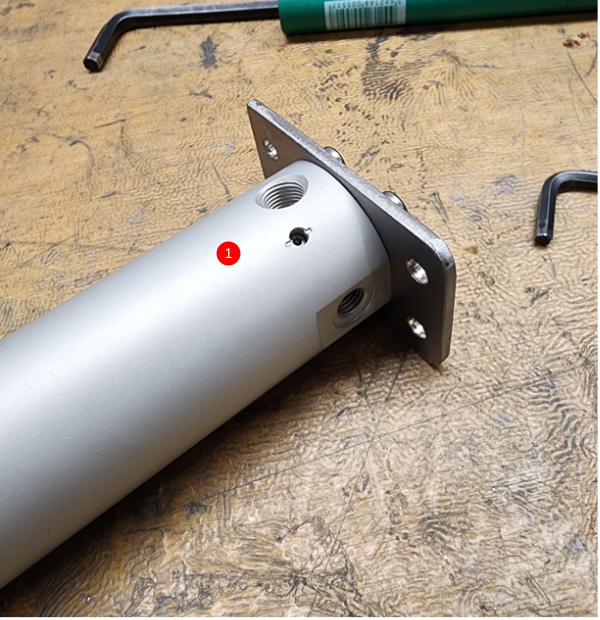
1 Use 4 off M5 x 12 socket caps and A Form washers to mount cylinder P0001044 to bracket D0010611
2 Use 4 off M5 x 16 socket caps and A Form washers to mount cylinder bracket to assembly. Leave these bolts loose until next steps are complete
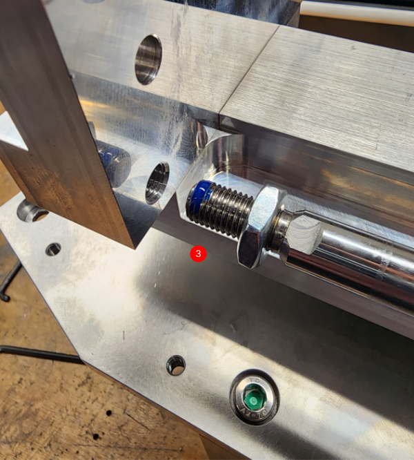
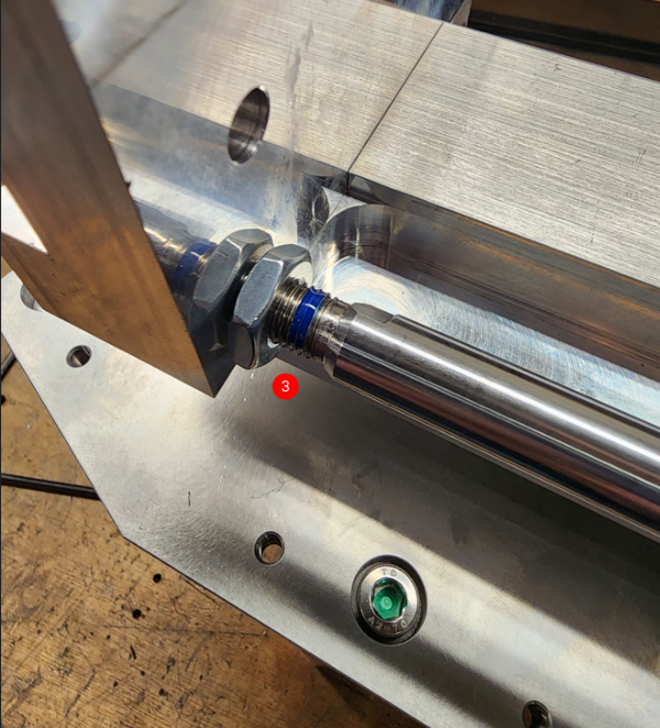
3 Attach cylinder piston. Set to position shown and finalise m10 locking nut
4 Contract assembly to closed position and finalise M5 x 16 socket caps holding top of cylinder. This will centralise cylinder into correct position for alignment .
5 Check cylinder stroke is smooth and consistent
Étape 11 -
Étape 12 -
Étape 13 -
Draft









 Français
 English
 Deutsch
 Español
 Italiano
 Português