Installation of rotary energy chain and back plates

Difficulté
Moyen
Durée
2 heure(s)
Sommaire
- 1 Introduction
- 2 Étape 1 - Adhesive
- 3 Étape 2 - Prepare 1st guide Section
- 4 Étape 3 - Fit Energy chain mounting bracket
- 5 Étape 4 - Prepare second section
- 6 Étape 5 - Prepare 3rd section
- 7 Étape 6 - Fit D0007817
- 8 Étape 7 - Fit D0003930
- 9 Étape 8 - Fit D0003985
- 10 Étape 9 - Fit locking screw to energy chain
- 11 Étape 10 - Modify plug and mount echain bracket
- 12 Étape 11 - Mount bracket
- 13 Étape 12 - Finalise energy chain cables
- 14 Étape 13 - Fit Access panel
- 15 Étape 14 - Add air ring main
- 16 Commentaires
Introduction
Tools Required
Étape 1 - Adhesive
All bolts must have Loctite 243 adhesive applied unless otherwise stated.
All bolts must be marked with pen once completed to indicate adhesive and correct tension has been applied

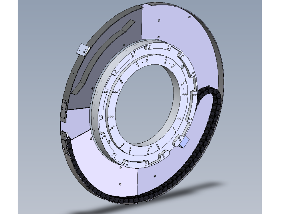
Étape 2 - Prepare 1st guide Section
D0003985 needs preparing before fitting
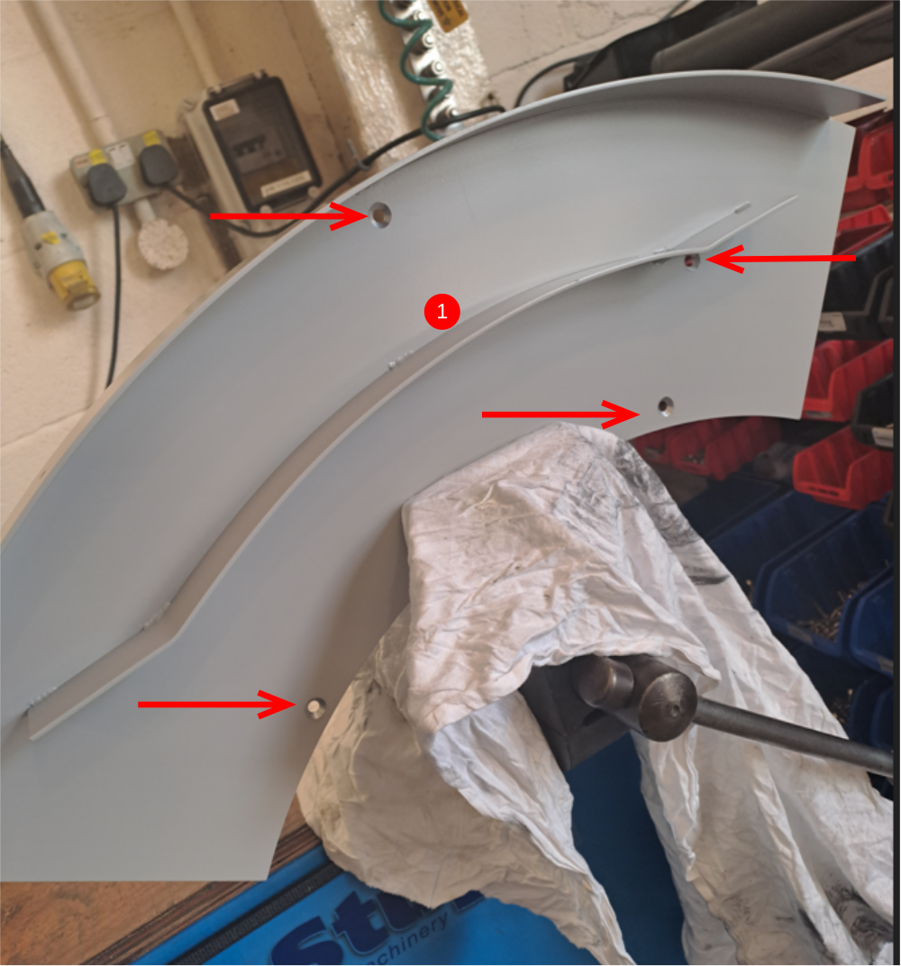
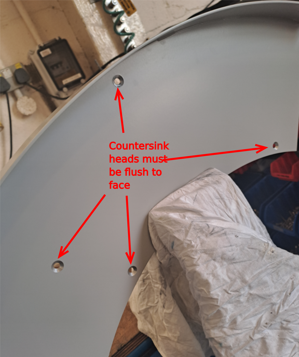
1 All back plates for the rotary trunking need to be checked for correct countersink depth. Any protrusion from main face will case energy chain failure
Check and if proud, use a countersink to increase depth

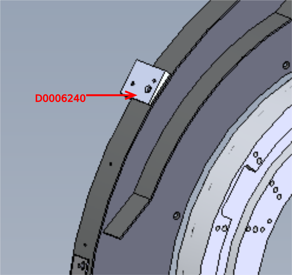
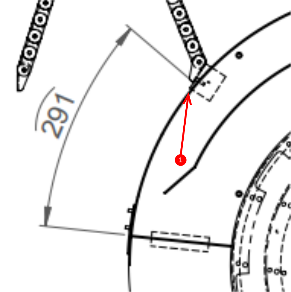
Étape 3 - Fit Energy chain mounting bracket
Mounting bracket D0006240 needs fitting to D0003985
1 Measure position of bracket onto circular guard (291mm)
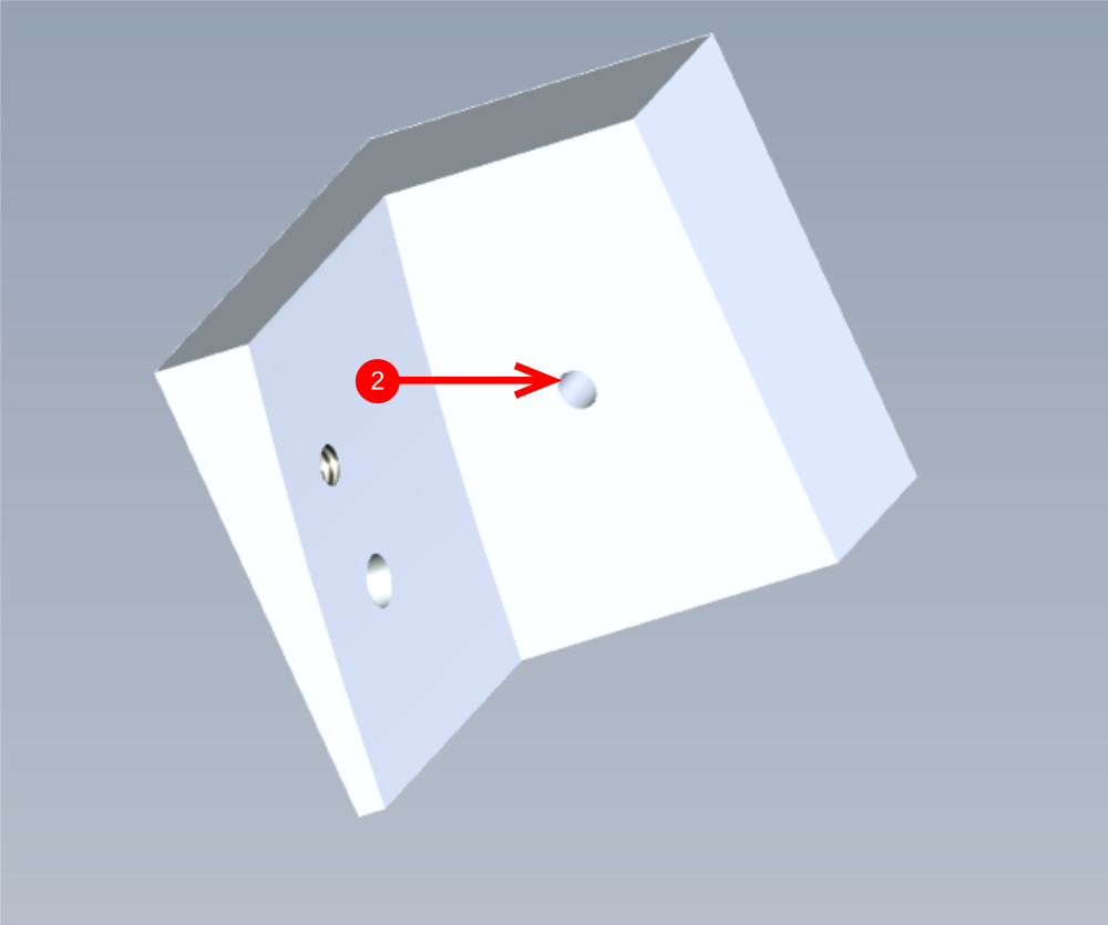
2 Use a pointed m5 grubscrew screwed into bracket hole indicated, hold in position on guard, and use hide hammer to transfer position mark
3 Drill to 6mm and fix bracket with m5x 16 cap head and large m5 washer
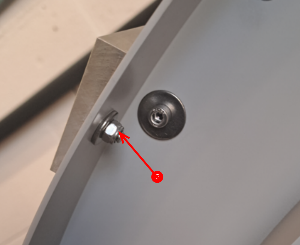
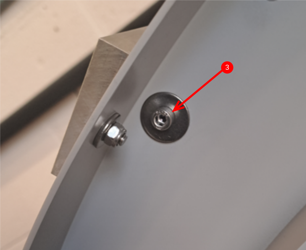
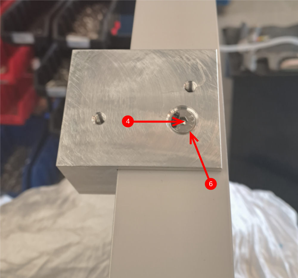
4 Drill 6mm through indicated hole
5 Fix with M5 x 16 countersink, large m5 washer and nyloc nut
6 This countersink bolt head must be flush to block. If proud, use a countersink bit to increase depth
Étape 4 - Prepare second section
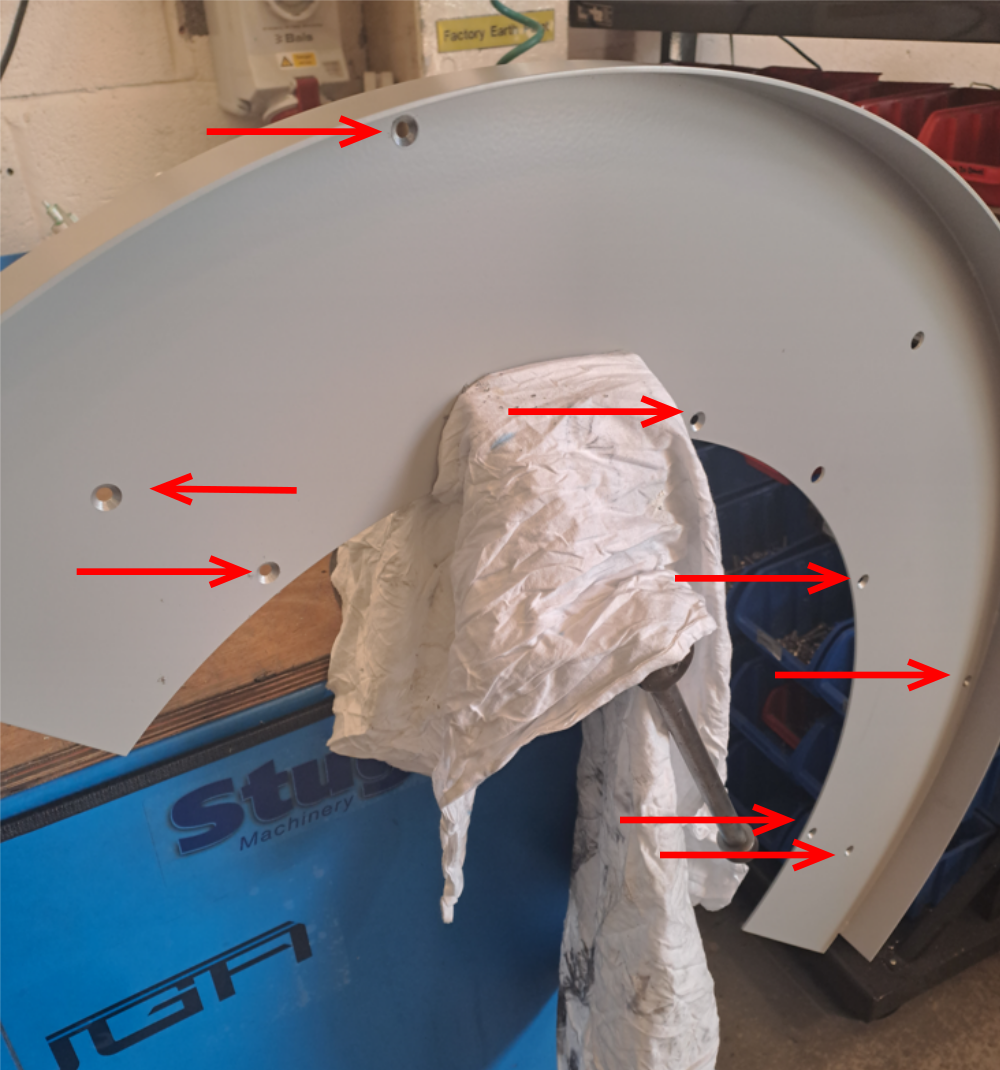
Check countersink holes in D0003930 are to the correct depth . Rework with countersink if fasteners sit proud.
Étape 5 - Prepare 3rd section
Check countersink holes in D0007817 are to the correct depth . Rework with countersink if fasteners sit proud.
Étape 6 - Fit D0007817
Mount D0007817 to main rotary base and fix with m5 x 10 countersink bolts

Étape 7 - Fit D0003930
Mount D0003930 to main rotary base and fix with m5 x 10 countersink bolts

Étape 8 - Fit D0003985
Mount D0003985 to main rotary base and fix with m5 x 10 countersink bolts

Étape 9 - Fit locking screw to energy chain
Drill and tap m3 to plugged end of energy chain assembly
Use m3 x 6 pan head bolt to secure
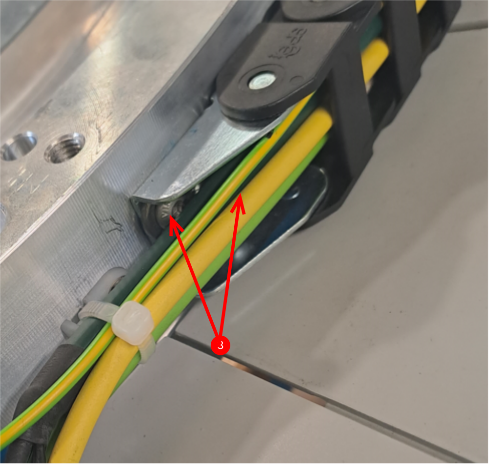
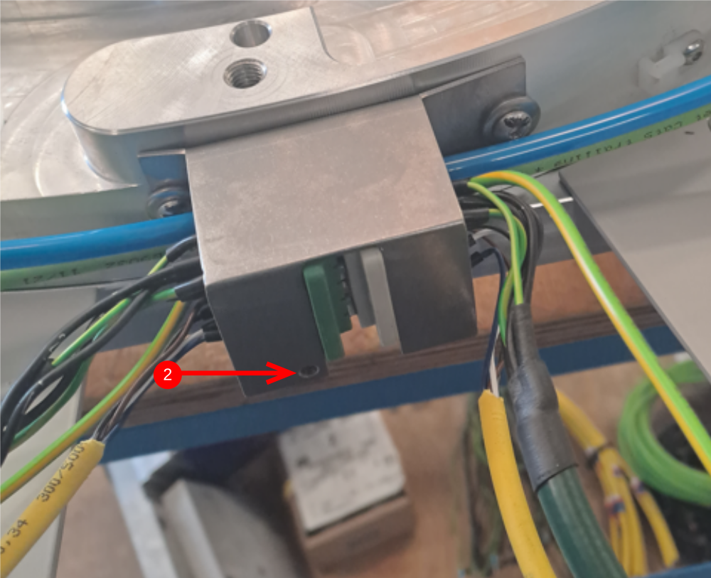
Étape 10 - Modify plug and mount echain bracket
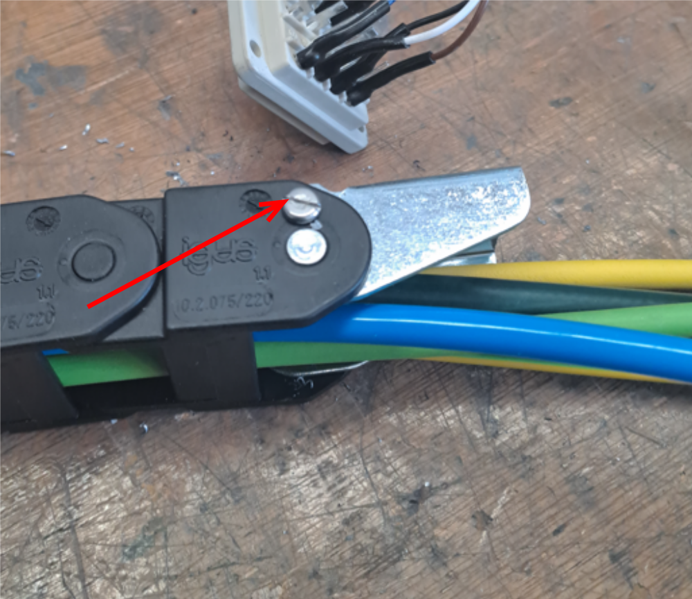
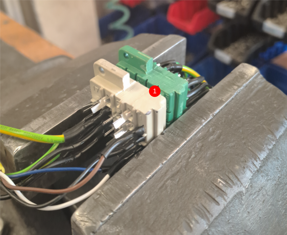
1 Modify plug to allow cable and pipe clearance as shown
2 Modification is required to give access as indicated
3 Attach chain bracket with 2 off m5 x 10 button head and washers
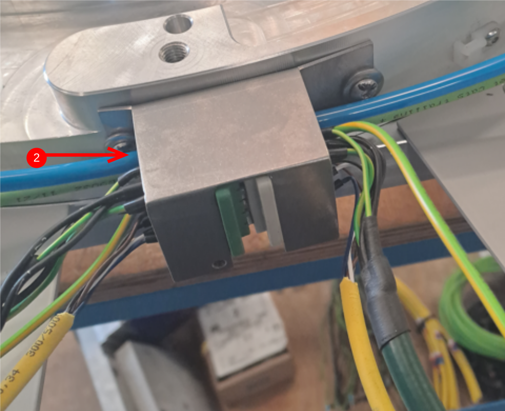
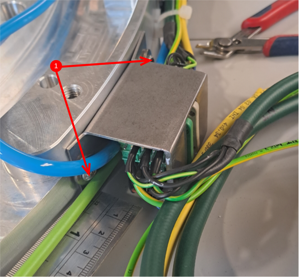
Étape 11 - Mount bracket
1 Mount bracket D0001171 using 2 off m5 x 16 button heads and heavy washers
2 Captivate plug with m4 x 12 socket cap
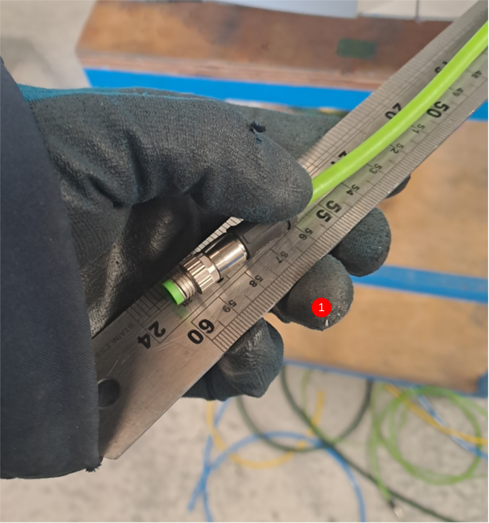
Étape 12 - Finalise energy chain cables
1 ensure 600mm of green ethercat cable is set
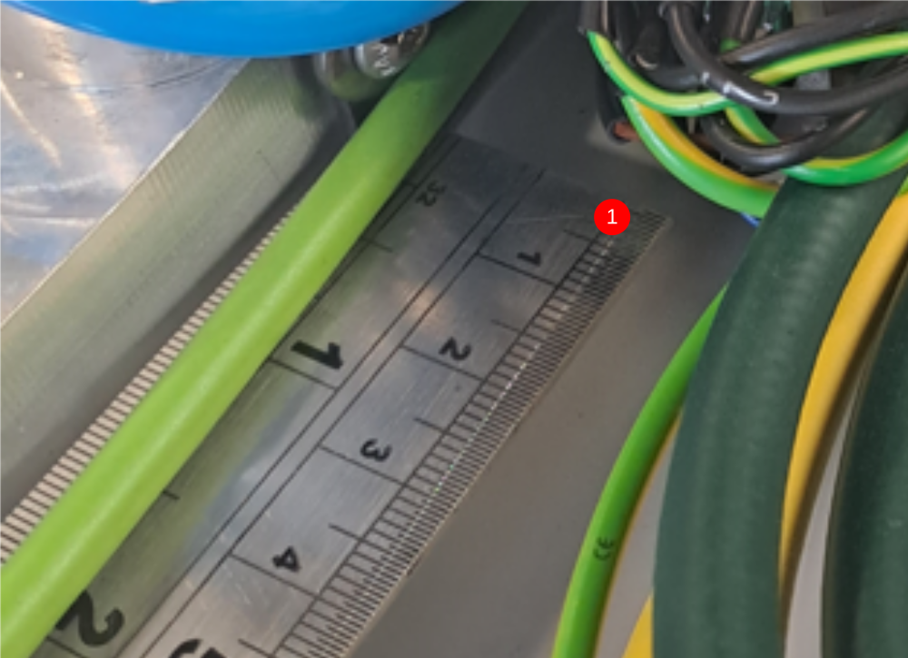
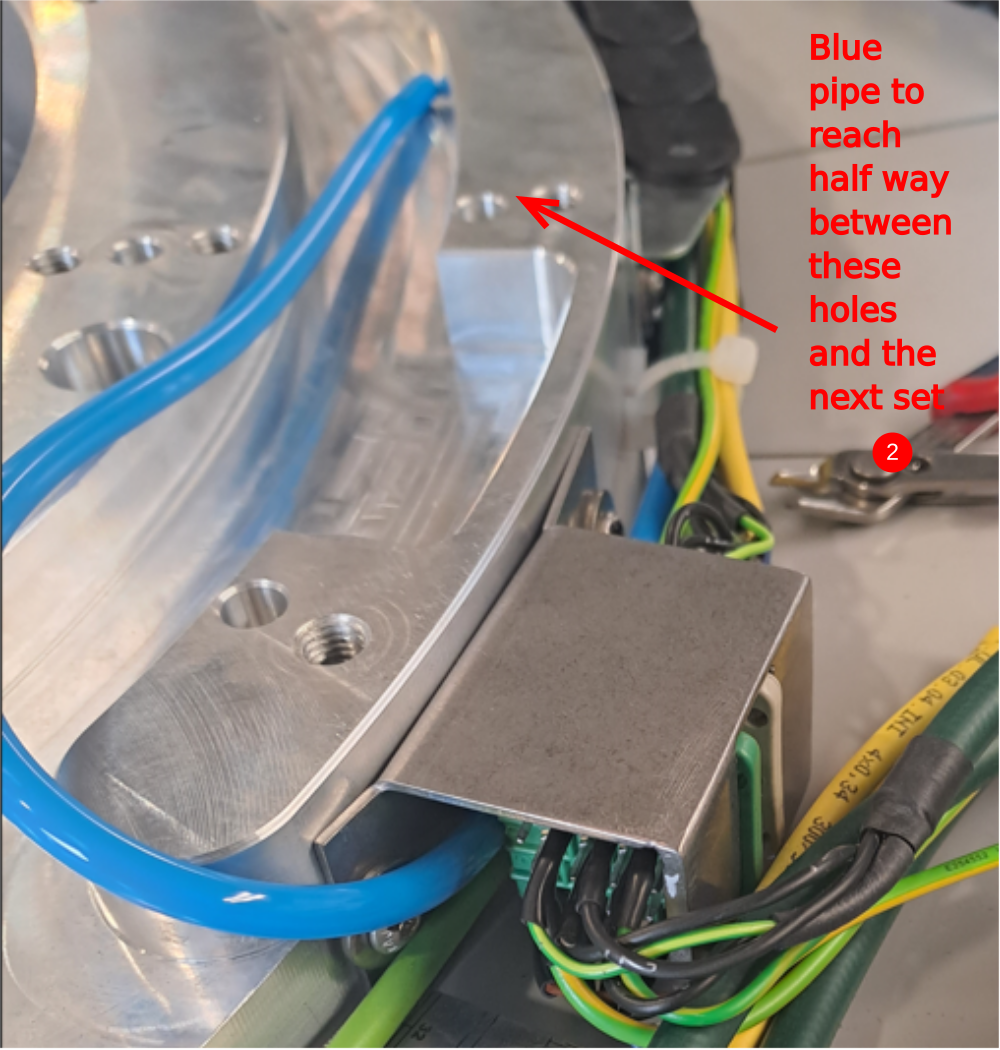
2 ensure 6mm blue pipe is set to position
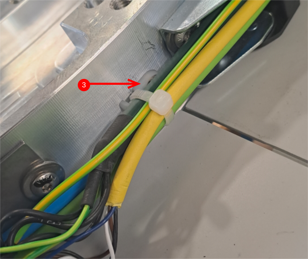
3 Ensure cable restraint is used once cable and pipe length are set ( M4 may need drilling )
Étape 13 - Fit Access panel
1 slide access panel into position
2 Fix energy chain to panel with m5 x 16 button heads, washers and nyloc nuts
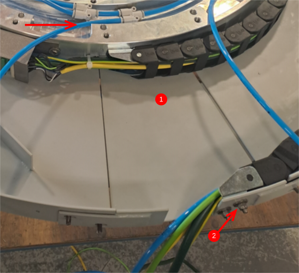
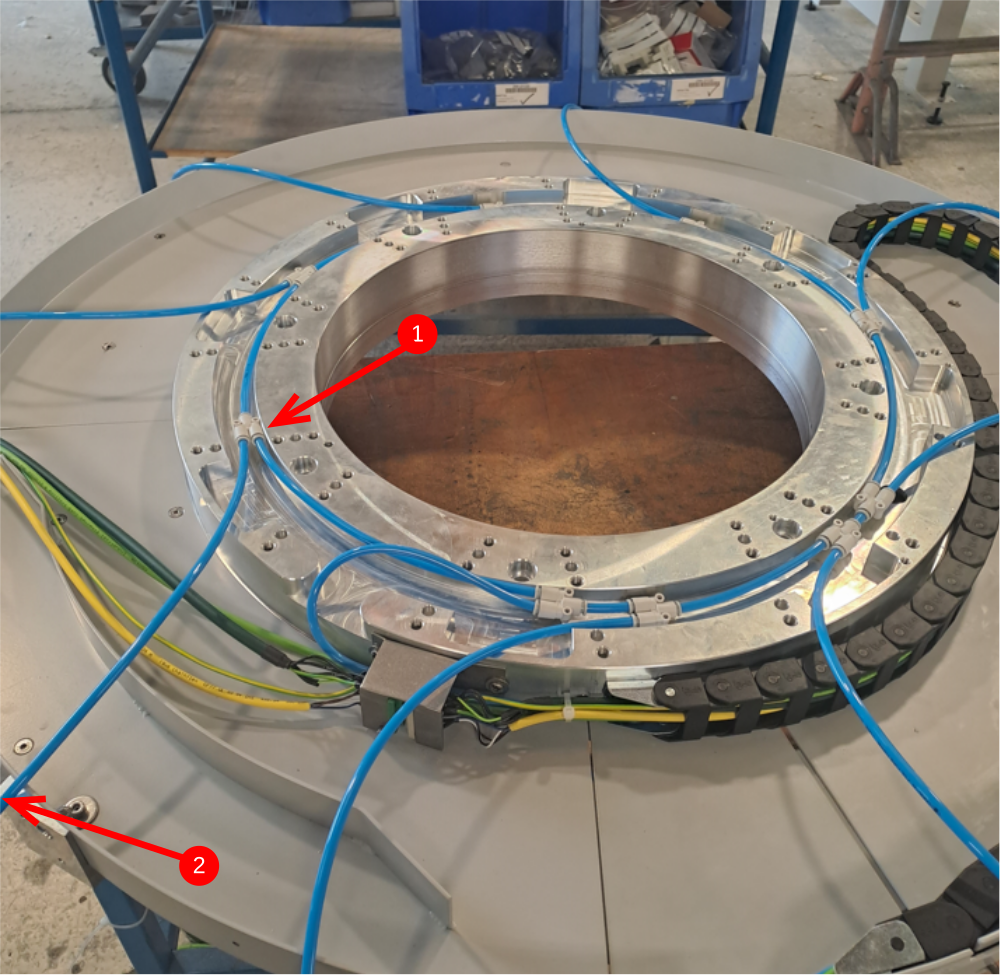
Étape 14 - Add air ring main
1 Connect ring main as shown. Ensure fittings P0001023 are placed in the same locations as shown in picture
2 Cap off 8 off ends of air pipe as shown
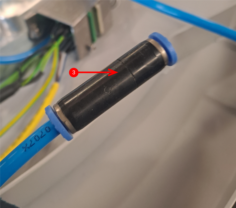
3 Add P0000401 to end of trailing 6mm blue pipe. Note orientation of non return valve
4 Purge system with air to perform pneumatic leak test. Once purged, system should hold pressure for minimum 1 hour
Draft
 Français
 English
 Deutsch
 Español
 Italiano
 Português