Key Steps for mechanical installation of ZX5

Difficulté
Très facile
Durée
4 jour(s)
Sommaire
- 1 Introduction
- 2 Étape 1 - Module Positioning
- 3 Étape 2 - Module order of positioning levelling
- 4 Étape 3 - Levelling of multi outfeed or saw infeed Y axis
- 5 Étape 4 - Levelling of multi outfeed or saw infeed X axis
- 6 Étape 5 - Position 2nd frame Saw infeed or Multi head outfeed
- 7 Étape 6 - Adjust height of 2nd levelled frame to match first
- 8 Étape 7 - Add 2 Transfer beams and Parallel set between hepco Rails
- 9 Étape 8 - Add remaining transfer beams
- 10 Étape 9 - Check and Set squareness of transfer table
- 11 Étape 10 - Multi head levelling points
- 12 Étape 11 - Alignment of Machining center to outfeed table
- 13 Étape 12 - Machining centre Infeed levelling
- 14 Étape 13 - Saw Machining centre Leveling
- 15 Étape 14 - Aligning Saw to saw infeed
- 16 Étape 15 - Saw outfeed table levelling points
- 17 Étape 16 -
- 18 Commentaires
Introduction
Key data for installation of ZX5
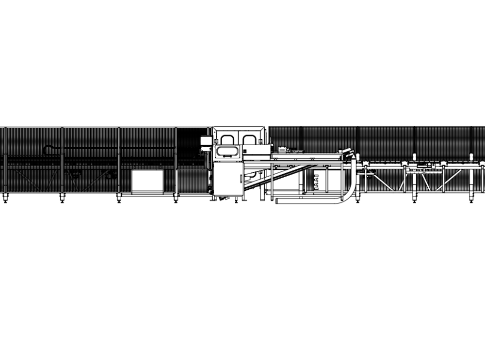
Étape 1 - Module Positioning
Identify if either saw infeed or multi head outfeed is the logical frame to place first .
Consider access to machine when installing 1st frame
Consider handing of machine
Étape 2 - Module order of positioning levelling
- Saw infeed or Multi head outfeed
- multihead outfeed or saw infeed
- transfer table
- Machining centre
- Machining centre infeed
- Saw module
- Saw outfeed table
- Conveyor
- Extraction
- Guarding
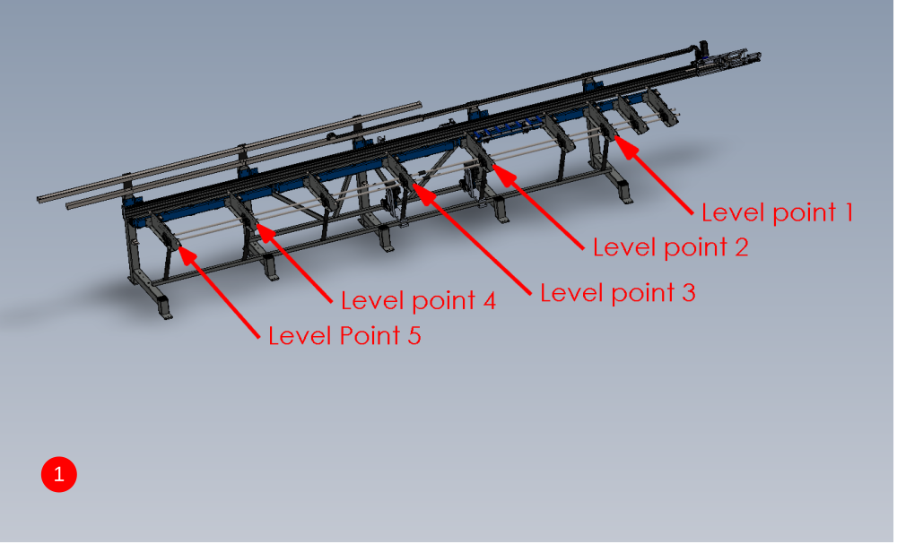
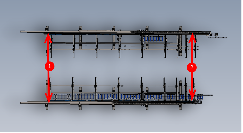
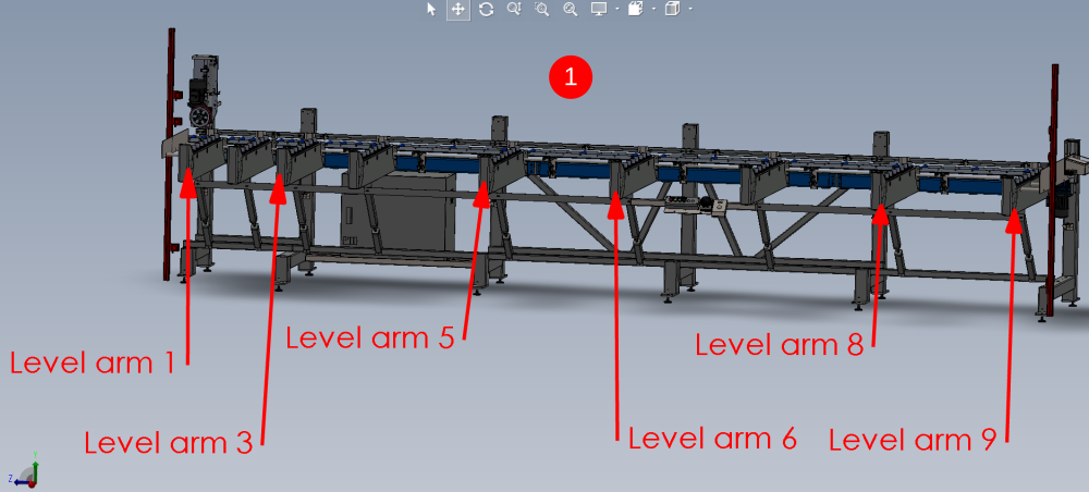
Étape 3 - Levelling of multi outfeed or saw infeed Y axis
Both frames will be initially levelled in the same way, and then fine tuned once multi head or saw is installed
Y axis levelling
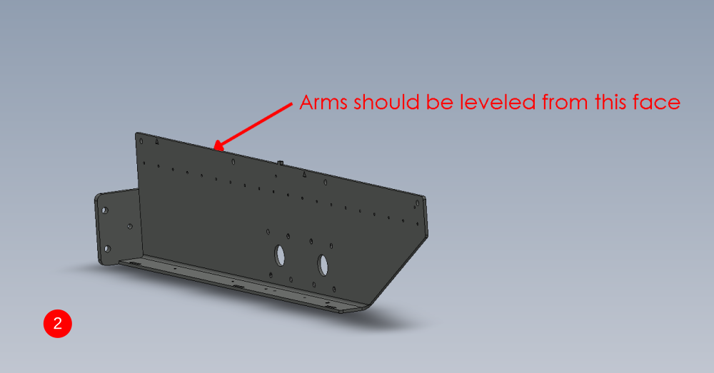
- Only level the arms at the positions indicated, as these are the only arms that sit directly above adjustment feet
- Level support arms from the indicated face

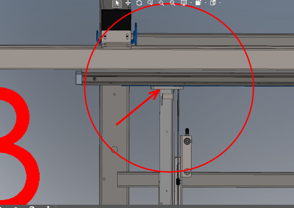
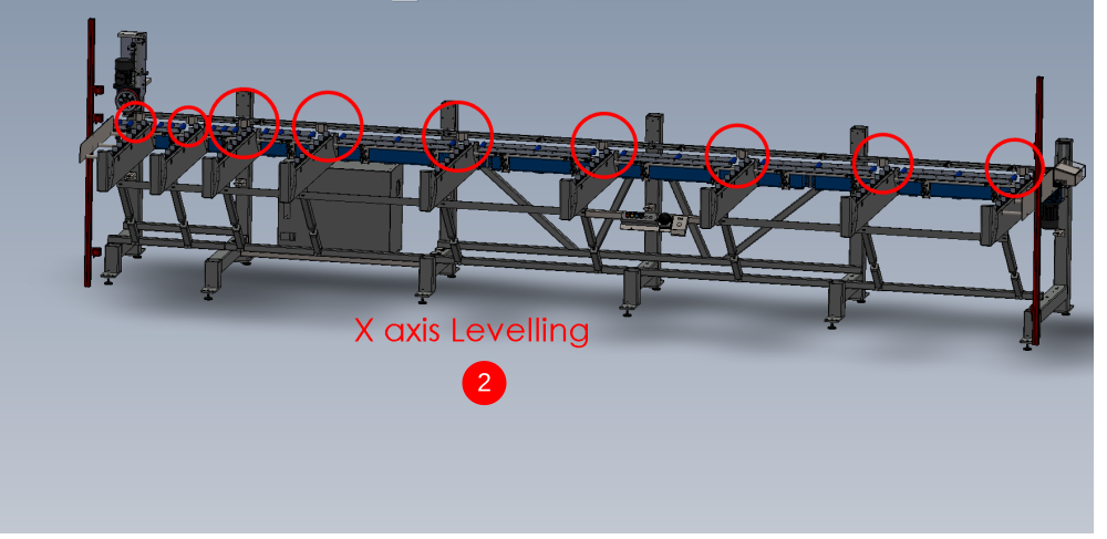
Étape 4 - Levelling of multi outfeed or saw infeed X axis
X axis is initially set up using the hepco rail as a register. Once additional units are installed and levelled , this x axis setting will be re checked and adjusted if required


Étape 5 - Position 2nd frame Saw infeed or Multi head outfeed
- Position second frame opposing first one which has been levelled
- Use measurement shown to set the frames roughly the correct distance apart
- Move the frame on the x axis to visually line up the support arms on both frame
- Level second frame using steps for levelling first frame above


Étape 6 - Adjust height of 2nd levelled frame to match first
Points A and B should be level with each other.
Adjust 2nd frame up or down on all frame bolts to achieve this

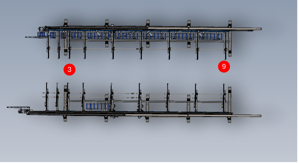
Étape 7 - Add 2 Transfer beams and Parallel set between hepco Rails
- Attach transfer beams 3 and 9 in there locations
- Add fasteners to beams to secure but leave loose enough for adjustment
- Measure the distance between the 2 hepco rails at the points shown on diagram 2 . Both indicated measurements should be the same . If not the slot in the transfer beam can be used to allow adjustment of this measurement to correct
- Tighten transfer beam fixings to hold frames in correct position
Étape 8 - Add remaining transfer beams
Add remaining 7 transfer beams to two installed frames and fix in position on support arms

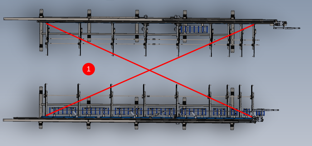
Étape 9 - Check and Set squareness of transfer table
It is crucial to set the squareness of the transfer table by adjusting the infeed/ outfeed tables.
1 The squareness can be checked by using a tape rule to make corner measurements at the points indicated
2 Second frame can be moved in the directions shown to adjust the corner measurements to make them both the same


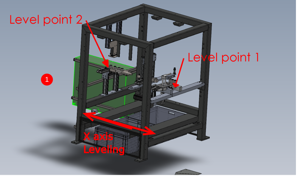
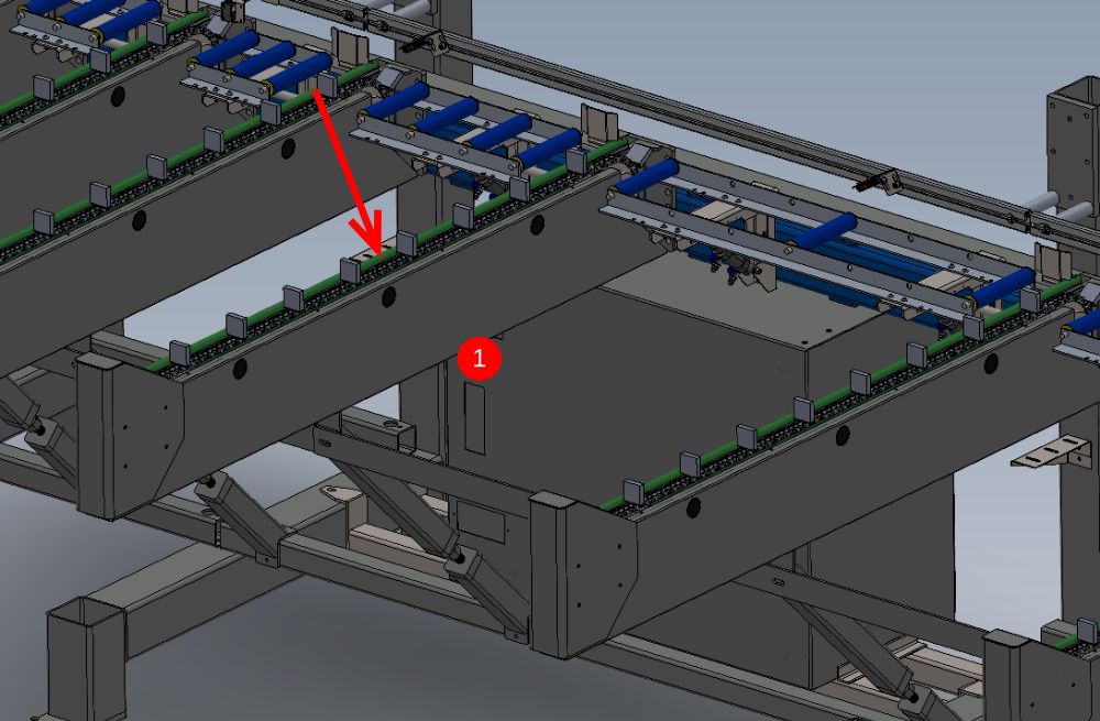
Étape 10 - Multi head levelling points
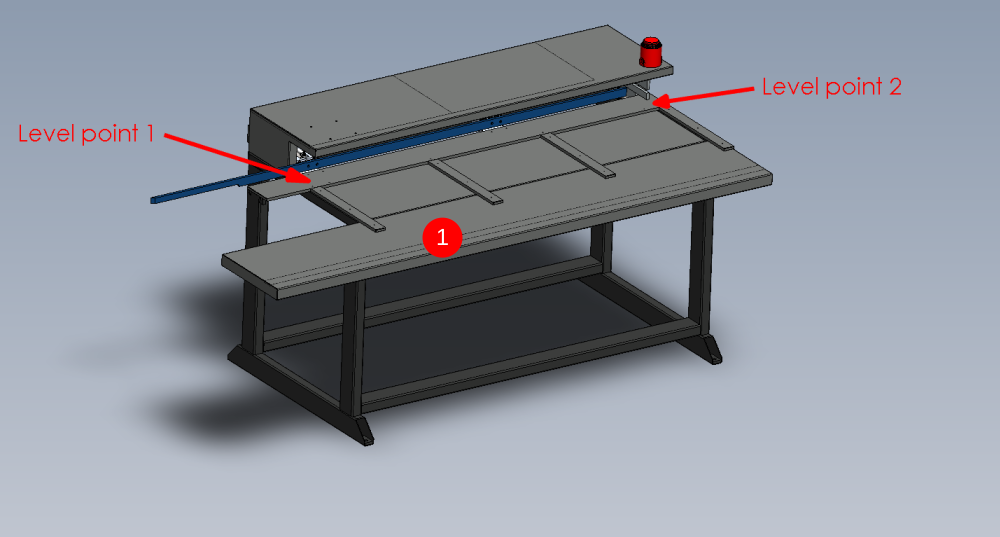
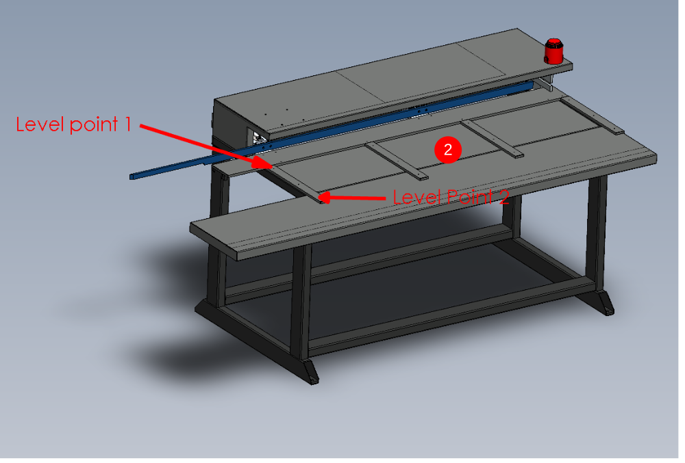
- x axis machine levelling. use a 2 meter straight edge between the indicated points and an engineers level on top to level this axis
- Y axis levelling. Use an engineers level to straddle the 2 indicated points to level the y axis of the machine
Étape 11 - Alignment of Machining center to outfeed table
Machining center is aligned to the out feed using the following
Grip pin setting jig
Laser level
2 meter straight edge
X axis position is determined by hepco rail travel at full extent and center clamp bar within machining center. The gap here should be approximately 10mm. However on installation position of this axis may be marked on the machine to be installed from previous installation
Y axis position is determined by the grip pin jig and the machining center backfence rollers
Height is determined by the datum horizontal rollers in the machining center and the blue rollers on the outfeed table
- position machining center roughly in place on the end of the outfeed table
- level using previous step
- once the module has been levelled, final levelling of the outfeed x axis can be done , as it uses the machining center as a datum to hold the laser level
Place laser level in the rear datum roller section of the machining center
Position gripper carriage as close to the laser level as possible
Mark a horizontal line of the carriage plate as a height datum
Move the carriage to above the next section of frame feet and adjust the pair of jacking bolts to adjust line to be on laser level mark
Repeat this step above every pair of frame legs where jacking bolts are
These steps will ensure the outfeed is now set on a dead flat plain
4. Use the pin jig to adjust the position of the machining center to allow the gripper pins to align with the jig at all points along the back fence rollers. hepco beam should also be moved from in to the out position also to double check this jig setting
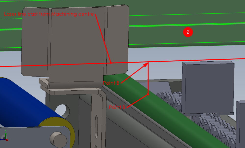
5. Use laser against machining center rollers to cast a laser line along the outfeed. Pull the gripper as close as possible to the laser, and mark a vertical line on the gripper where the laser dot falls.
Move the gripper to the end of the hepco rail and check if the laser stop still aligns on the vertical line previously marked . If it doesn't , grip pin alignment will need re checking as it is crucial that both of these areas are correct
6 final height adjustment is set by using a 2 meter straight edge through the machining center rollers to the first set of rollers on the outfeed table. Machining center can be adjusted up or down to bring these rollers all onto the same height plain

Étape 12 - Machining centre Infeed levelling
- Levelling Y axis of machining centre infeed . This is done on the indicated face of the arms using a level . Only level the indicated arms as these are the only ones controllable by the jacking feet positions
- Use a laser level placed on the levelled machining centre infeed rollers, and cast a laser line along the length of the infeed table. Ensure the beam is positioned so a reading can be taken from each circled point on the frame. Take a measurement from the first circled point with a steel rule of the indicated area. Replicate this measurement at all points indicated along the frame by Adjusting the legs in pairs to raise or lower the appropriate arm
- When height setting to the machining centre, the whole frame can simply be jacked up or down to achieve the correct height in relationship to the machining centre
.Purge air onto active line of roller output to lift rollers for height setting
Étape 13 - Saw Machining centre Leveling
Saw machining module is levelled from the indicated point


Étape 14 - Aligning Saw to saw infeed
- Y axis alignment
Saw back fence and saw infeed back fence are used for y axis alignment . Saw back fence should be slightly in front of saw infeed back fence. Around 1mm
2. X axis alignment
Frames should be marked to show measurement between frames to set this position . if not the defining factor is the gripper must not hit eject clamps when at full travel on x axis
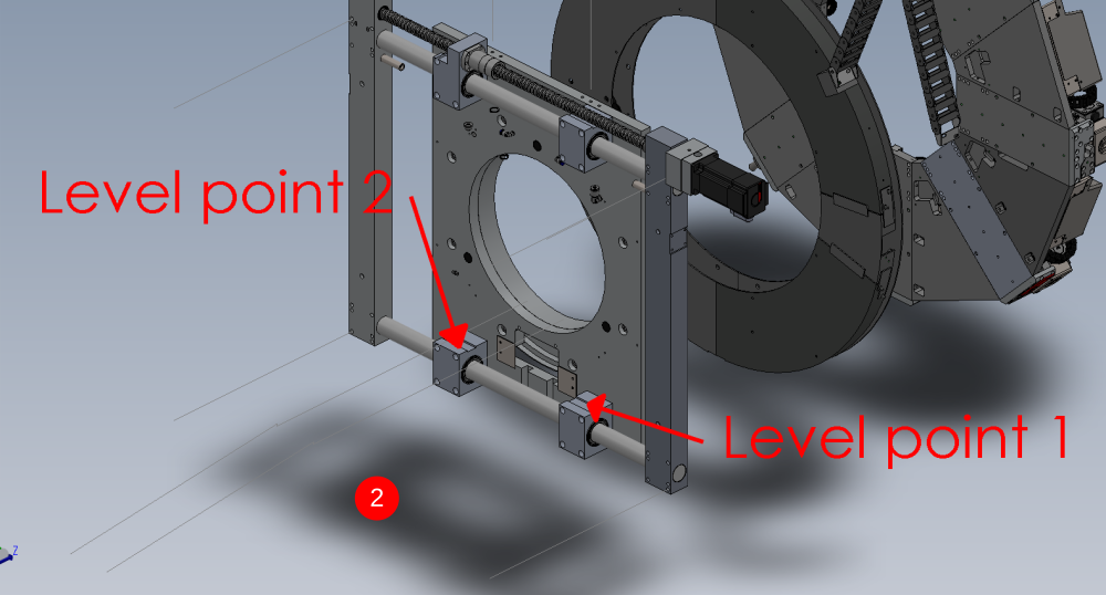
Étape 15 - Saw outfeed table levelling points
- X axis of module is levelled from the two indicated points . Use a 2 meter straight edge between these points and an engineers level on top
- y axis is levelled from these two indicated points . an engineers level rested on this face is sufficient for levelling
Étape 16 -
Draft
 Français
 English
 Deutsch
 Español
 Italiano
 Português