Key Steps for mechanical installation of ZX5

Difficulté
Moyen
Durée
16 heure(s)
Sommaire
- 1 Introduction
- 2 Étape 1 - Module Positioning
- 3 Étape 2 - Module order of positioning levelling
- 4 Étape 3 - Levelling of multi outfeed or saw infeed Y axis
- 5 Étape 4 - Levelling of multi outfeed or saw infeed X axis
- 6 Étape 5 - Position 2nd frame Saw infeed or Multi head outfeed
- 7 Étape 6 - Adjust height of 2nd levelled frame to match first
- 8 Étape 7 - Add 2 Transfer beams and Parallel set between hepco Rails
- 9 Étape 8 - Add remaining transfer beams
- 10 Étape 9 - Check and Set squareness of transfer table
- 11 Étape 10 - Multi head levelling points
- 12 Étape 11 - Machining centre Infeed levelling
- 13 Étape 12 - Saw Machining centre Leveling
- 14 Étape 13 - Saw outfeed table levelling points
- 15 Étape 14 -
- 16 Commentaires
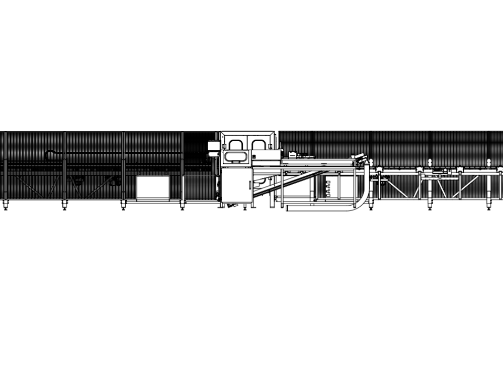
Introduction
Key data for installation of ZX5
Étape 1 - Module Positioning
Identify if either saw infeed or multi head outfeed is the logical frame to place first .
Consider access to machine when installing 1st frame
Consider handing of machine
Étape 2 - Module order of positioning levelling
- Saw infeed or Multi head outfeed
- multihead outfeed or saw infeed
- transfer table
- Machining centre
- Machining centre infeed
- Saw module
- Saw outfeed table
- Conveyor
- Extraction
- Guarding
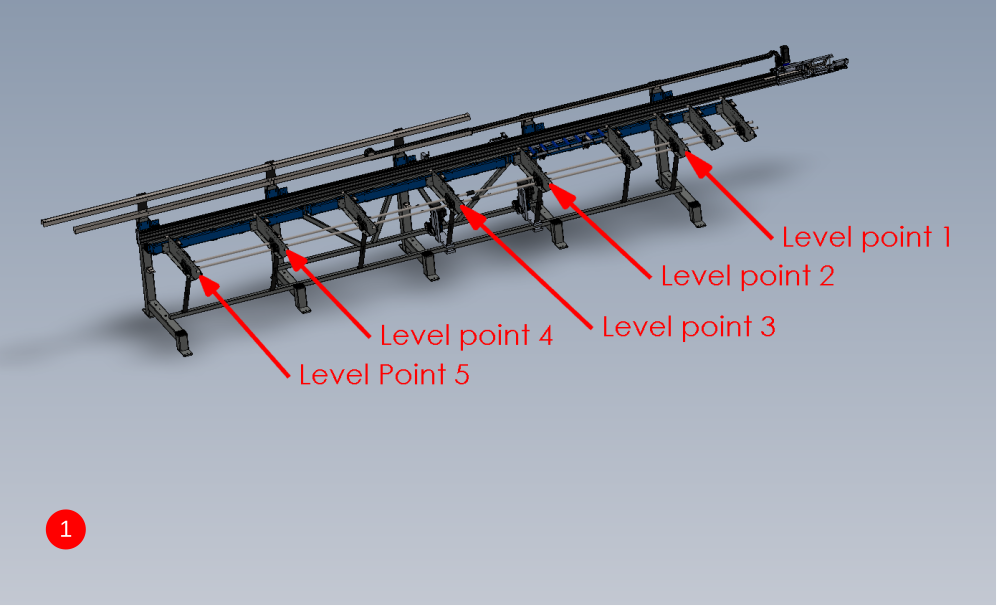
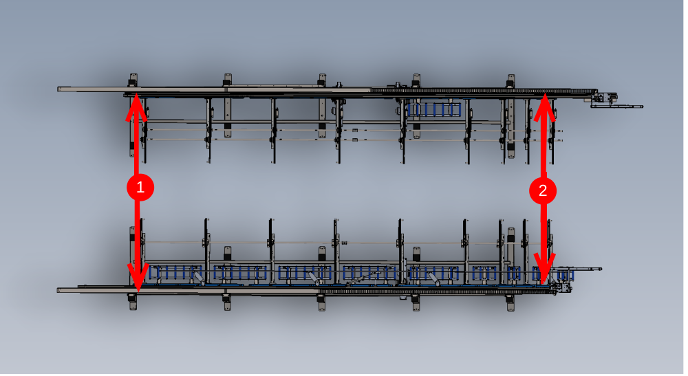
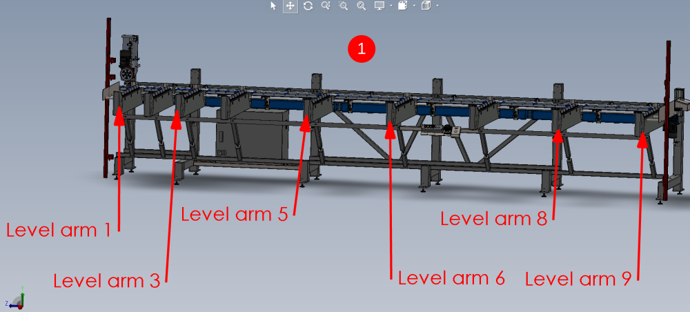
Étape 3 - Levelling of multi outfeed or saw infeed Y axis
Both frames will be initially levelled in the same way, and then fine tuned once multi head or saw is installed
Y axis levelling
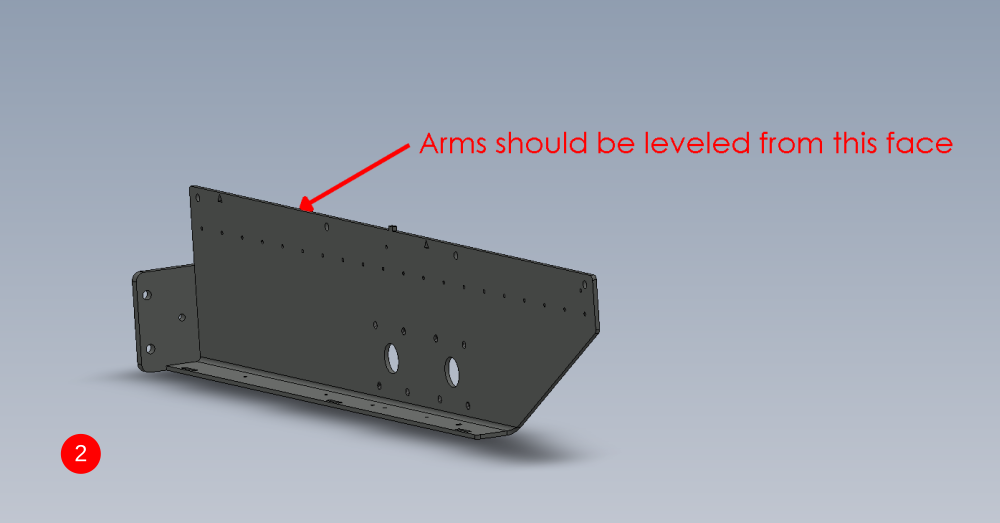
- Only level the arms at the positions indicated, as these are the only arms that sit directly above adjustment feet
- Level support arms from the indicated face

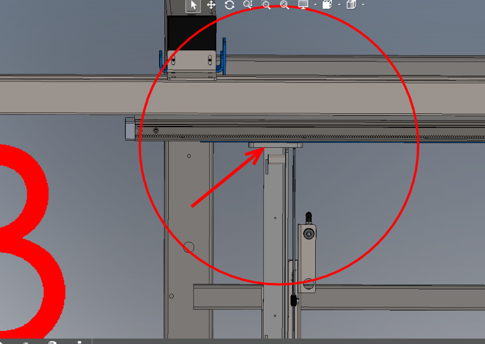
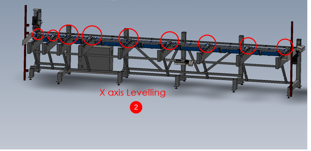
Étape 4 - Levelling of multi outfeed or saw infeed X axis
X axis is initially set up using the hepco rail as a register. Once additional units are installed and levelled , this x axis setting will be re checked and adjusted if required


Étape 5 - Position 2nd frame Saw infeed or Multi head outfeed
- Position second frame opposing first one which has been levelled
- Use measurement shown to set the frames roughly the correct distance apart
- Move the frame on the x axis to visually line up the support arms on both frame
- Level second frame using steps for levelling first frame above


Étape 6 - Adjust height of 2nd levelled frame to match first
Points A and B should be level with each other.
Adjust 2nd frame up or down on all frame bolts to achieve this

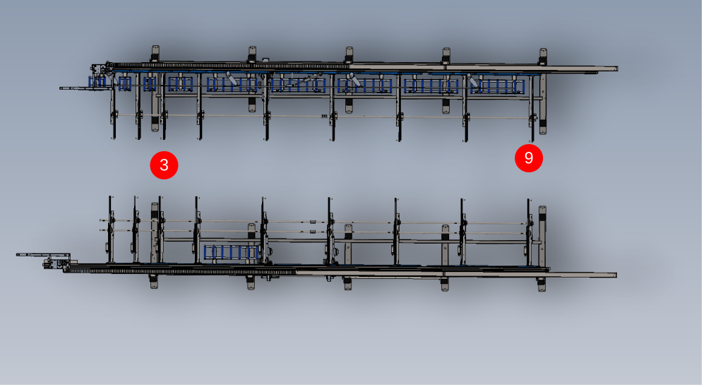
Étape 7 - Add 2 Transfer beams and Parallel set between hepco Rails
- Attach transfer beams 3 and 9 in there locations
- Add fasteners to beams to secure but leave loose enough for adjustment
- Measure the distance between the 2 hepco rails at the points shown on diagram 2 . Both indicated measurements should be the same . If not the slot in the transfer beam can be used to allow adjustment of this measurement to correct
- Tighten transfer beam fixings to hold frames in correct position
Étape 8 - Add remaining transfer beams
Add remaining 7 transfer beams to two installed frames and fix in position on support arms

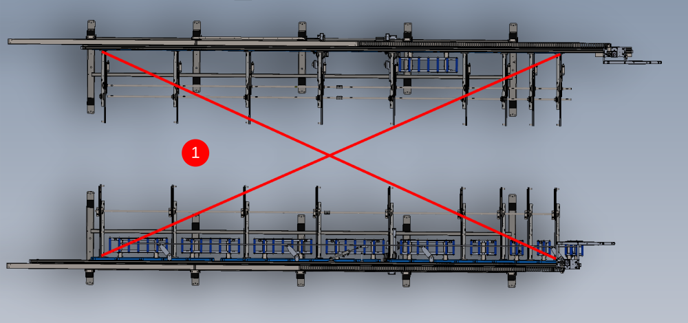
Étape 9 - Check and Set squareness of transfer table
It is crucial to set the squareness of the transfer table by adjusting the infeed/ outfeed tables.
1 The squareness can be checked by using a tape rule to make corner measurements at the points indicated
2 Second frame can be moved in the directions shown to adjust the corner measurements to make them both the same


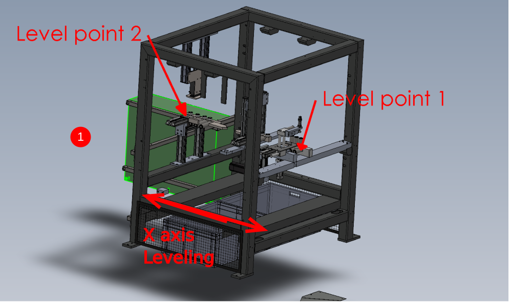
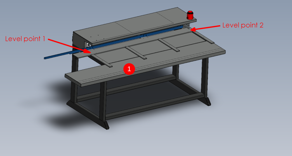
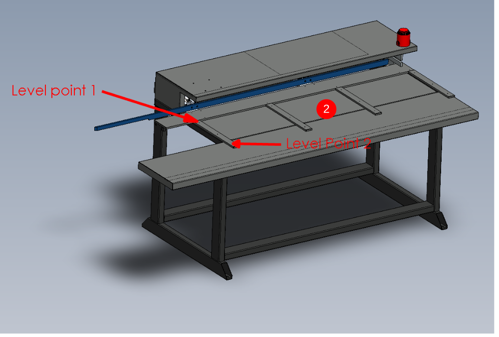
Étape 10 - Multi head levelling points
- x axis machine levelling. use a 2 meter straight edge between the indicated points and an engineers level on top to level this axis
- Y axis levelling. Use an engineers level to straddle the 2 indicated points to level the y axis of the machine
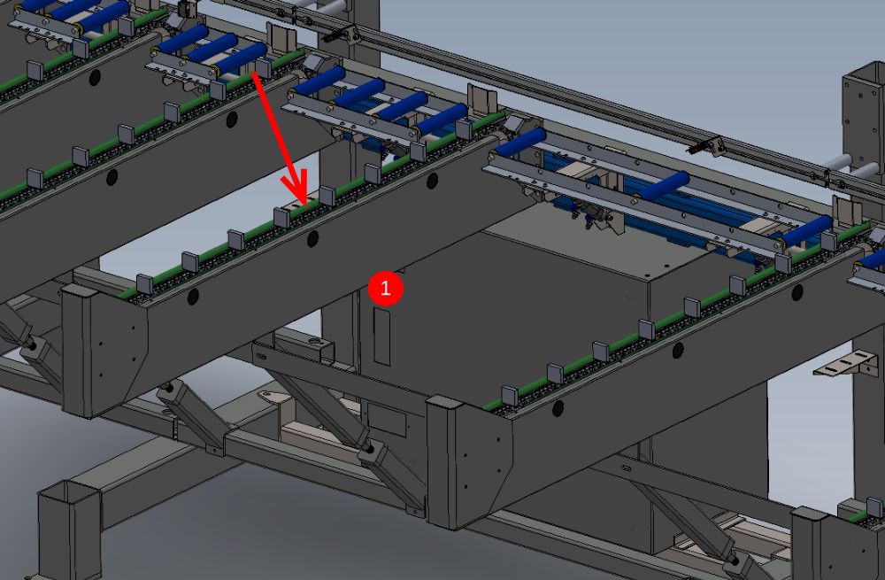
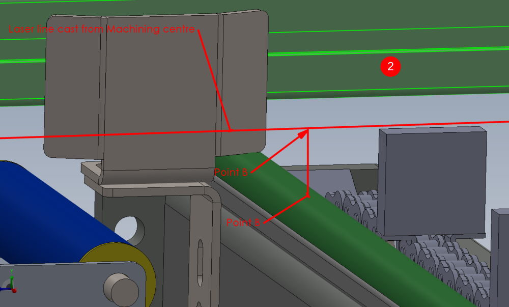
Étape 11 - Machining centre Infeed levelling
- Levelling Y axis of machining centre infeed . This is done on the indicated face of the arms using a level . Only level the indicated arms as these are the only ones controllable by the jacking feet positions
- Use a laser level placed on the levelled machining centre infeed rollers, and cast a laser line along the length of the infeed table. Ensure the beam is positioned so a reading can be taken from each circled point on the frame. Take a measurement from the first circled point with a steel rule of the indicated area. Replicate this measurement at all points indicated along the frame by Adjusting the legs in pairs to raise or lower the appropriate arm
- When height setting to the machining centre, the whole frame can simply be jacked up or down to achieve the correct height in relationship to the machining centre
Étape 12 - Saw Machining centre Leveling
Saw machining module is levelled from the indicated point


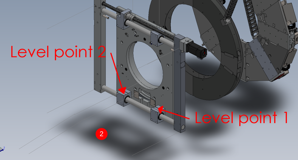
Étape 13 - Saw outfeed table levelling points
- X axis of module is levelled from the two indicated points . Use a 2 meter straight edge between these points and an engineers level on top
- y axis is levelled from these two indicated points . an engineers level rested on this face is sufficient for levelling
Étape 14 -
Draft
 Français
 English
 Deutsch
 Español
 Italiano
 Português