Autoflow MK4 GY&GZ axis setup with Jetter Motors

Difficulté
Moyen
Durée
2 heure(s)
Sommaire
- 1 Introduction
- 2 Étape 1 - Initial Preperation
- 3 Étape 2 - GY Axis:
- 4 Étape 3 - GZ Axis
- 5 Étape 4 - Counterbalance
- 6 Étape 5 - CX5203 Firmware Upgrade
- 7 Étape 6 - Drive Manager 2 and Support Jetter Files
- 8 Étape 7 - Basic Assumptions
- 9 Étape 8 - GY setup Motor
- 10 Étape 9 - GY Setup FeedBack
- 11 Étape 10 - GY Setup Scaling
- 12 Étape 11 - GY Setup Tuning
- 13 Étape 12 - GY Setup Commutation step 1 P-0-150
- 14 Étape 13 - GY Setup Commutation angles
- 15 Commentaires
Introduction
WARNING:
The Jetter motor on the GZ axis has a brake. Release the brake without control could be harmful.
Use the Air Counterbalance rig to assist if necessary.
Étape 1 - Initial Preperation
Ensure that the profile support arm is held out of the way to avoid marking the blue infeed arm.
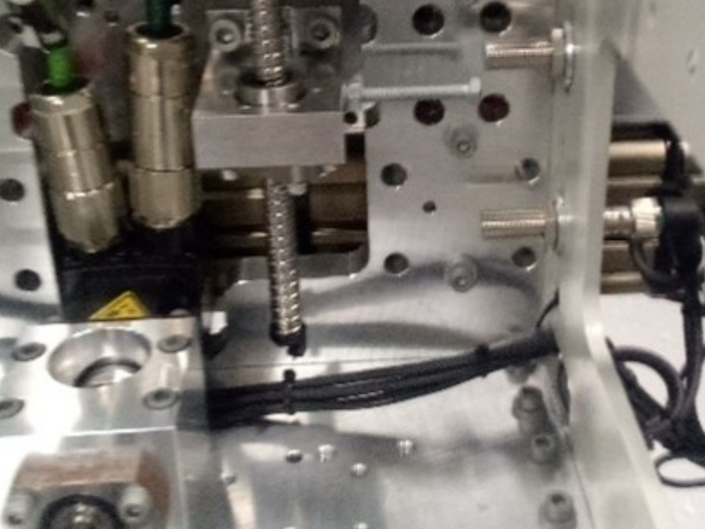
Étape 2 - GY Axis:
Check that proximity arm is in between the proximity sensor.
You should be able to turn the leadscrew by hand to move it.

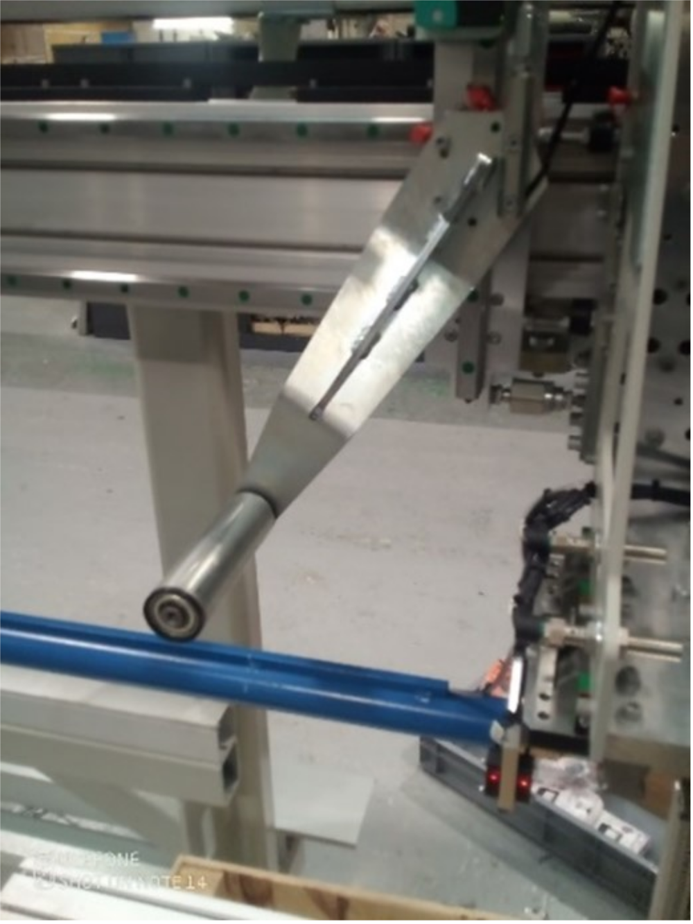
Étape 3 - GZ Axis
Check that proximity arm is in between the proximity sensor
This has a brake and you can only turn the leadscrew by hand if the counterbalance is fitted.

Étape 4 - Counterbalance
Counterbalance fitted under the carriage.
Adjust the pressure until you can turn the leadscrew of the GZ axis by hand. (6 bar)
.

Étape 5 - CX5203 Firmware Upgrade
The firmware on the CX5203 must be high enought to be supported under Drive manager 2.
Because your have to remove and add drives back into a projecct crate a new projet just to update the drives.
- Expand I/O -> Devices-> Device (EthercAT), Doble click and open the Onlne tab.
- Check the Dirve you are going to update is in OP state and right mouse click on it.
- Select FIRMWARE UP. Navidate to the location of the firmware. Normally C:\TwinCAT\Functions\TE5950-Drive-Manager-2\Firmware\AX5000
- Do the same process for the EEROM matching the version number.
- Check that you have the XML definition file for the version of firmware in C:\TwinCAT\3.1\Config\Io\EtherCAT\Beckhoff AX5xxx
- With this done you should be able to delete the drives and add them bak and check under drive manager 2


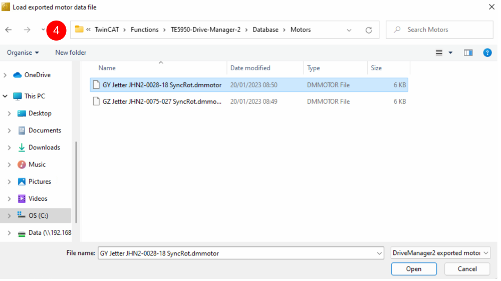
Étape 6 - Drive Manager 2 and Support Jetter Files
Ensure Drive Manager 2 is installed (Verion 1.1.60.0 minimum)
Copy the files from :
G:\Design\TwinCAT3\Other Motor Definition Files
GY Jetter JHN2-0028-18 SyncRot.dmmotor
GZ Jetter JHN2-0075-027 SyncRot.dmmotor
to C:\TwinCAT\Functions\TE5950-Drive-Manager-2\Database\Motors
Étape 7 - Basic Assumptions
The Motors are connected to an AX5203 Drive
GY on the A channel
GZ on the B channel
The Drive is labelled GY & GZ
The channels are mapped to AXIS with appropriate names
A Driver Manager 2 Project exisits with the Drives in it.


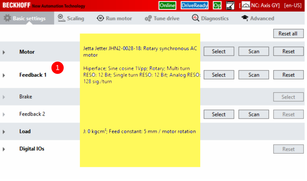
Étape 8 - GY setup Motor
- Double click on GY axis (Ch A ) in drive manager 2 . You will not see the information highlighted yet.
- For the Motor Press select then select the filter options.
- Select Import.
- Move to the folder C:\TwinCAT\Functions\TE5950-Drive-Manager-2\Database\Motors
- Select the GY and Open
- The parameters shold all mactch the screen shots.

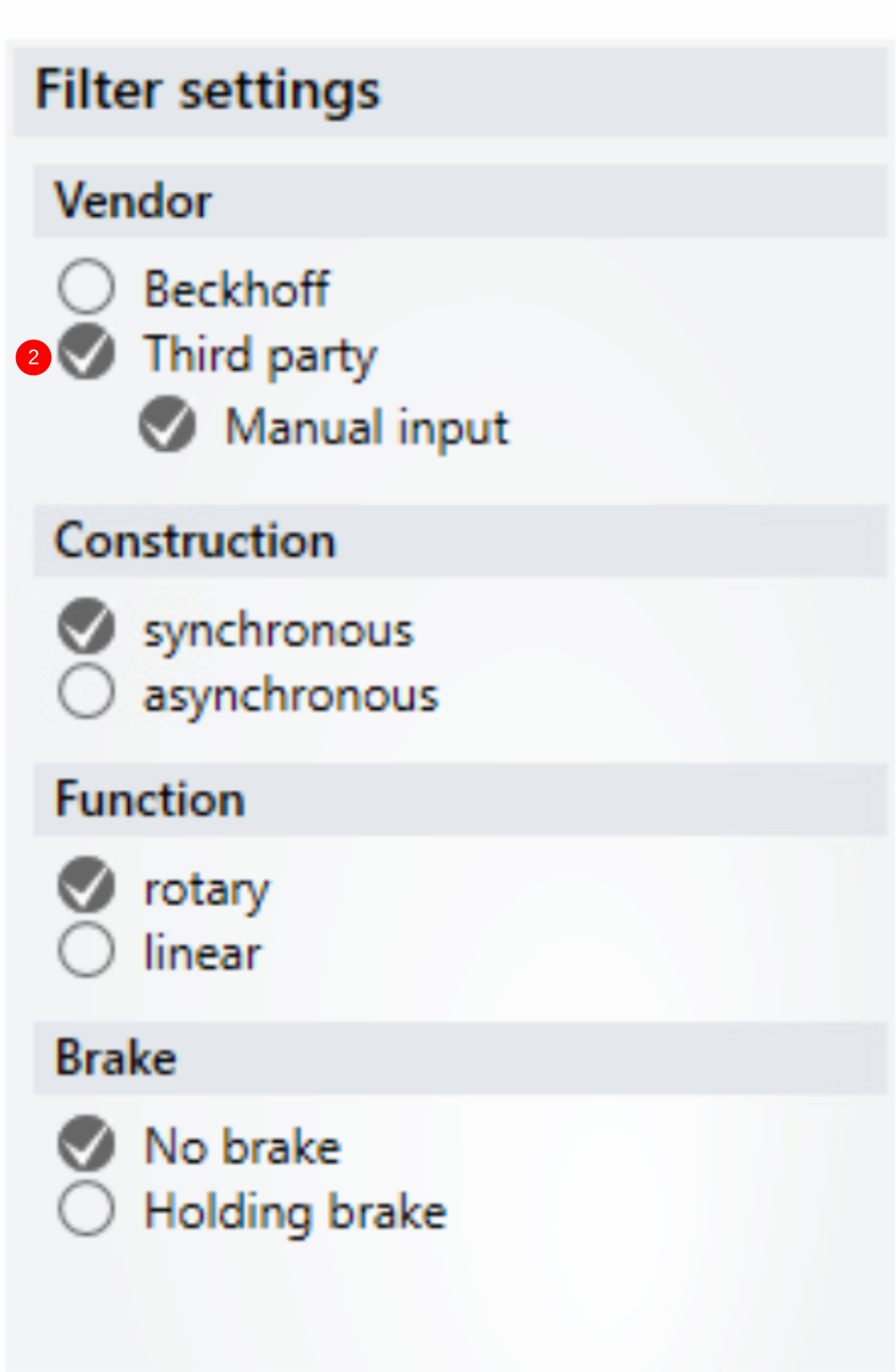


Étape 9 - GY Setup FeedBack
- From the Manager Scrren Press Select fo "Feedback 1"
- Under filter Select as shown (Hiperface being the important one)
- Expand Sick#SKx and select SKM36- HFA0-S05 and OK

Étape 10 - GY Setup Scaling
- Select the Scaling Tab
- Adjust the settings HightLighted.
- When Checking the INVERT boes you will get a request to activate it straight away. Do not both as you have to activate all setting down later.
- Before you save the NC Parameters Look at the values in red. If the new value is different to the Online value of the screen shot detick the is selected box so that it does not update.


Étape 11 - GY Setup Tuning
- Select the Tune Drive tab
- Set Kp = 0.02
- Set Kp=85.2
- Set Kv=25
- Set Tn=3.0
- Set Tn 0.8

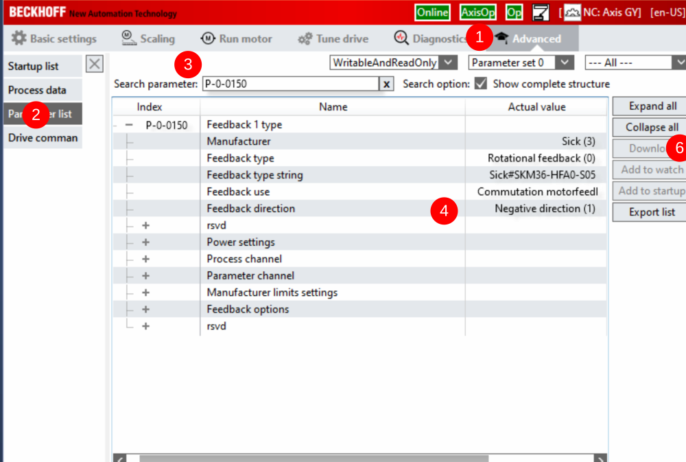
Étape 12 - GY Setup Commutation step 1 P-0-150
- Select th Advance tab
- Select Prameter List
- In search Type P-0-150
- Check the settings
- You may have to change the Feedback direction to Negative
- If you change it remeber to press download after the change
Étape 13 - GY Setup Commutation angles
There are two forms of commutation set up Mechanical and Electrical.
Mechical is going to be 0 degrees and we are going to adjust the electrial using the command P-0-0166
Draft
 Français
 English
 Deutsch
 Español
 Italiano
 Português