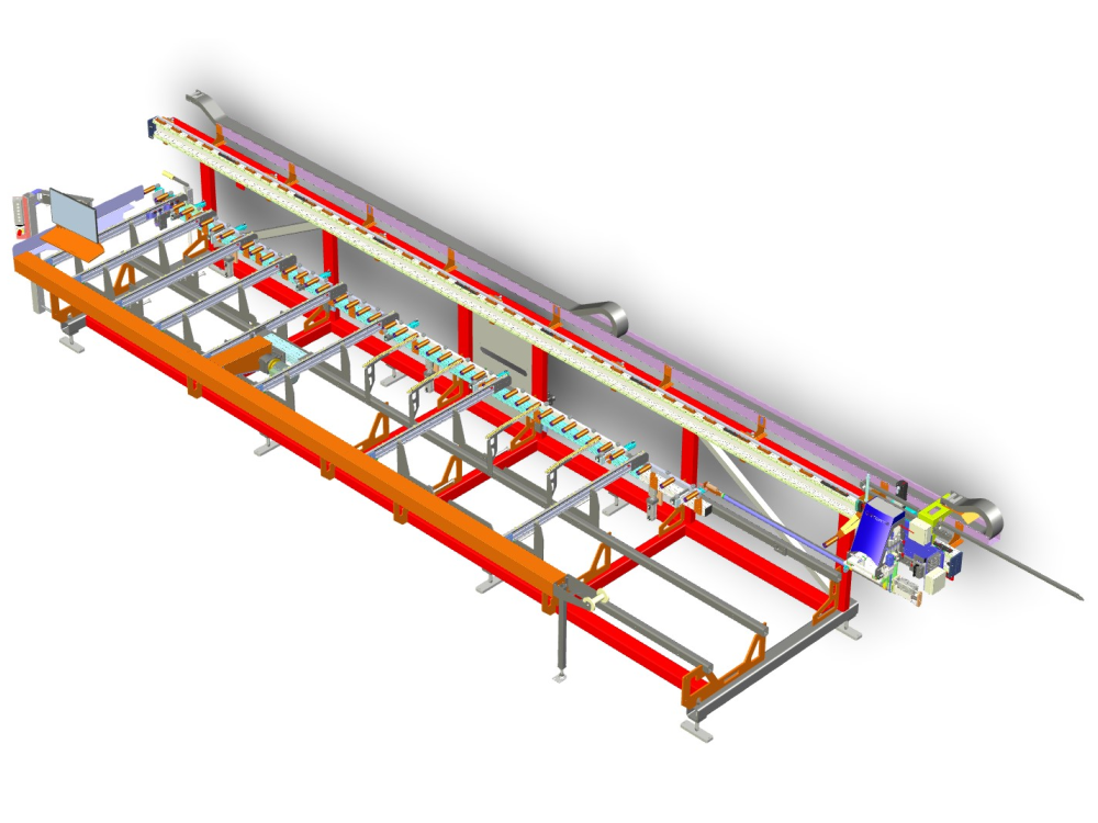
Critical measurements and settings for an Autoflow infeed table

Sommaire
Method
- Use the gripper arm as the measuring stick. The datum must be set so that zero is the spindle centreline.
- The measure point is when the gripper nose switch is depressed
| Measurement | Description | A2027 Value | Photo |
|---|---|---|---|
| Machining Centre to Infeed spacing | Distance between centrelines of feet | 500 | |
| Zero Datum | Centreline of spindles | 0 | |
| measureStartPosX | Measuring start position
Should be so that measure sensor is on machining centre side of the profile load fence |
-880 | |
| infeedToZeroX | Distance from zero to profile load fence (profile side) | 615 | |
| measureSensorPos1
measureSensorPos2 |
Distance of gripper nose (depressed) to offcut measure sensors
Sensor 1 nearest MH |
1460
1480 |
|
| GX Axis Max position | Maximum travel on GX Axis
After datum, press estop and manually move to end of travel Note the value and subtract 10mm |
7255 | |
| GX Move After Datum | Ideally set to max profile length+infeedZeroToX+100 | 6500+600+100
=7200 |
|
| stopCylinderToZeroX | Distance from the spindle centreline to the stop cylinder
|
585 | |
| loadOffsetX | Relative distance to move after measuring finished to allow gripper to clear end of bar.
This can be measured - end of gripper "swan neck" to measuring sensor
|
1580 | |
| GX Minimum Position | Absolute minimum position of GX
Goal is for gripper nose switch to at least reach saw blade Ensure the end rubber buffers are set to prevent a mechanical clash beween the |
-1040 | |
| Infeed Horizontal side clamp positions | These are set up in the clamp setup as the "GripPos" for OuA_P2BFOnx |
1-950
2-1480 3-2600 4-3700 5-4800 6-6300 7-7050 |
|
| GY Min Position | Limited by the backfence clamping in the saw area | 10 | |
| GY Max Position | 54 | ||
| GZ Min Position | Gripper must not bottom out on the saw tables | 6 | |
| GZ Max position | 70 |
Draft
 Français
 English
 Deutsch
 Español
 Italiano
 Português