
How to create a new TwinCAT3 Project from scratch

Difficulté
Difficile
Durée
4 heure(s)
Sommaire
- 1 Introduction
- 2 Étape 1 - Add Drive Manager 2 for AX8000 drives (if not installed already)
- 3 Étape 2 - Start a new project
- 4 Étape 3 - Add PLC Project for tcMulti
- 5 Étape 4 - Add PLC Project for Reset
- 6 Étape 5 - Ensure Correct Machine Commented in tcMulti project
- 7 Étape 6 - Add TwinSAFE project
- 8 Étape 7 - Add the route to the PLC
- 9 Étape 8 - Scan for Devices
- 10 Étape 9 - Check EtherCAT validity
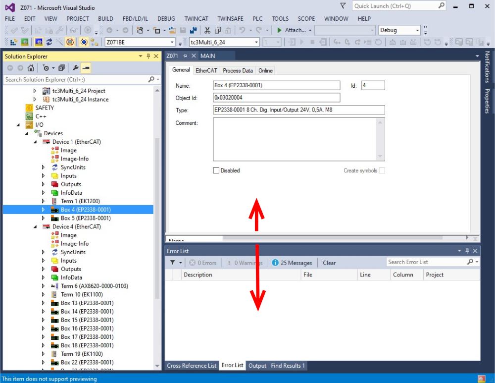
- 11 Étape 10 - Name all EtherCAT devices according to network
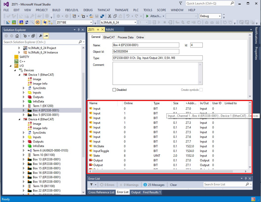
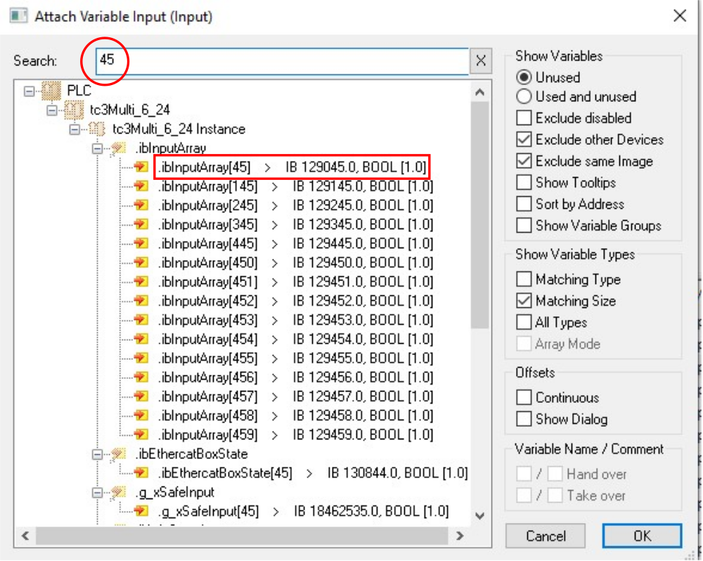
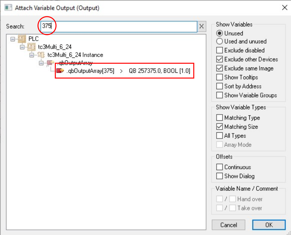
- 12 Étape 11 - Map all IO References
- 13 Étape 12 - Double check all IO references with someone else
- 14 Étape 13 - Activate configuration
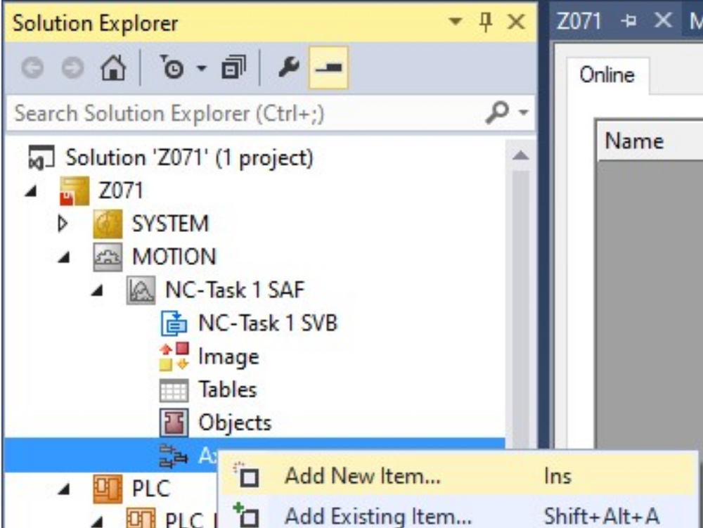
- 15 Étape 14 - Add Axis Task
- 16 Étape 15 - Add Axes
- 17 Étape 16 - Map Axes
- 18 Étape 17 - Install Drive Manager 2 Project
- 19 Étape 18 - Add PLC_Reset to tc3Multi Link
- 20 Commentaires
Introduction
Étape 1 - Add Drive Manager 2 for AX8000 drives (if not installed already)
- Copy the Drive Manager 2 setup g:\design\TwinCAT3\TE5950-TC3-Drive-Manager-2.zip to Install Files on the PC running Visual Studio
- Close Visual Studio
- Extract the Zip File
- Run the Setup File
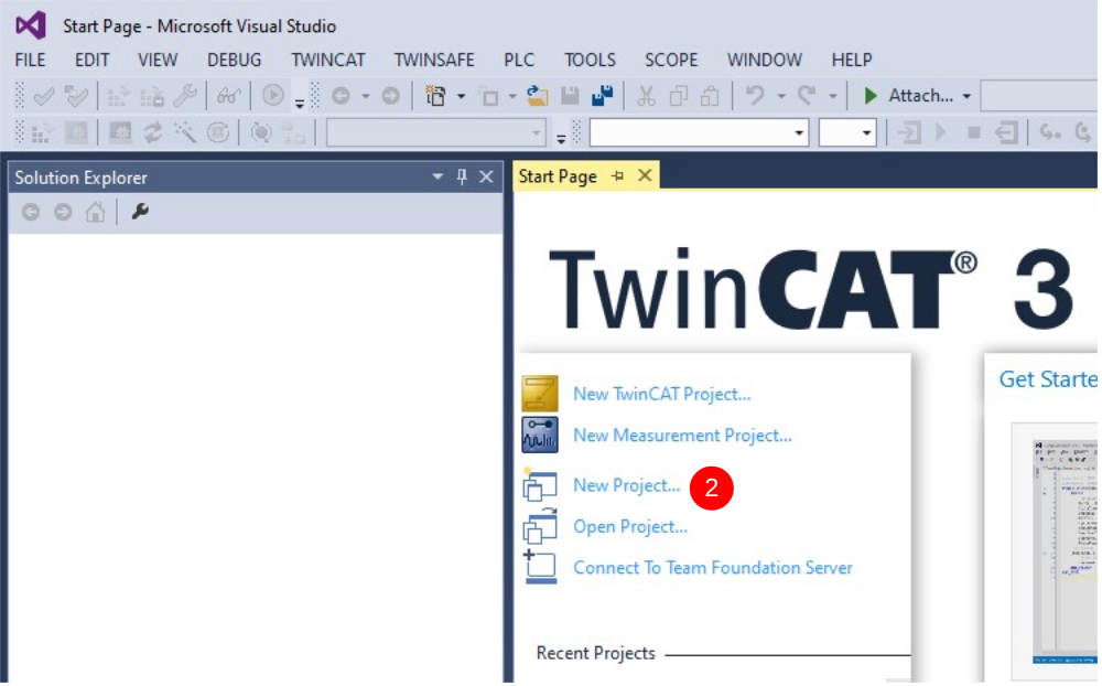
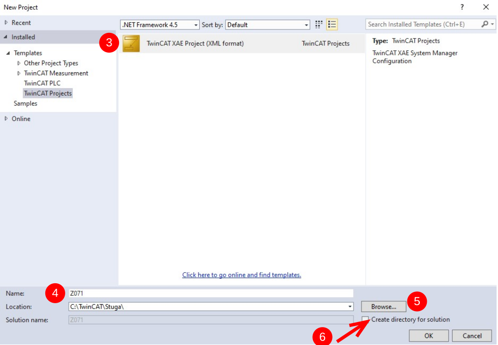
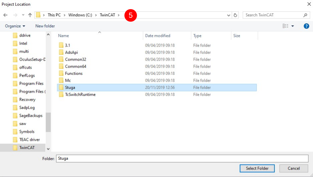
Étape 2 - Start a new project
- Open Visual Studio
- Click on New project
- Choose TwinCAT projects->TwinCAT XAE Project (xml format)
- Name is build number (no Suffix)
- Location is c:\TwinCAT\Stuga\
- Untick "Create Directory for solution"
This creates the template
Étape 3 - Add PLC Project for tcMulti
- Add Existing Item
- Navigate to g:\Design\TwinCAT3\tcMulti_6_24
- Select the .Plcproj file
- Copy Project to solution file


Étape 4 - Add PLC Project for Reset
- On PLC, right click and Add Existing Item
- Navigate to g:\Design\TwinCAT3\PLC_Reset_1_1
- Select the .Plcproj file
- Copy Project to solution file

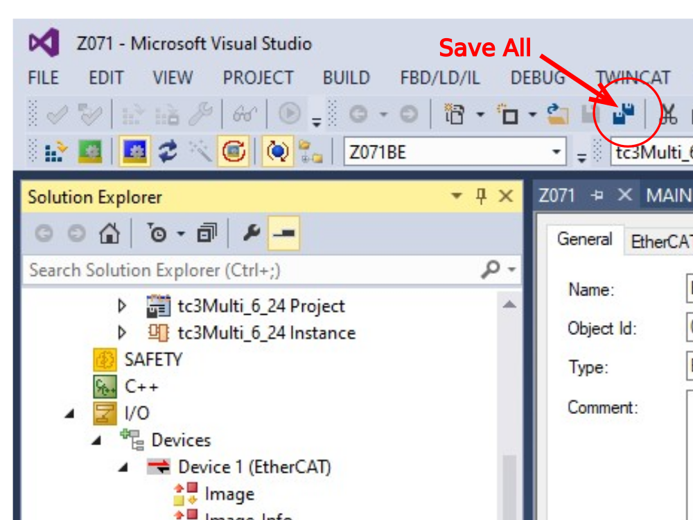
Étape 5 - Ensure Correct Machine Commented in tcMulti project
- Navigate to tcMulti_6_24 project->POUs->MAIN
- Scroll down to the machine types. The "comment State" can be toggled on and off by right clicking next to the step number on the left
- Your goal is to ensure the correct machine is highlighted and the incorrect ones are commented out (in green)
- Click Save All

Étape 6 - Add TwinSAFE project
Étape 7 - Add the route to the PLC
- From Dropdown box select the Build number (If it does not exist we will need to add a new route)
- If there is a request for a platform change, click Yes
- On success, the Route dropdown will not read Error


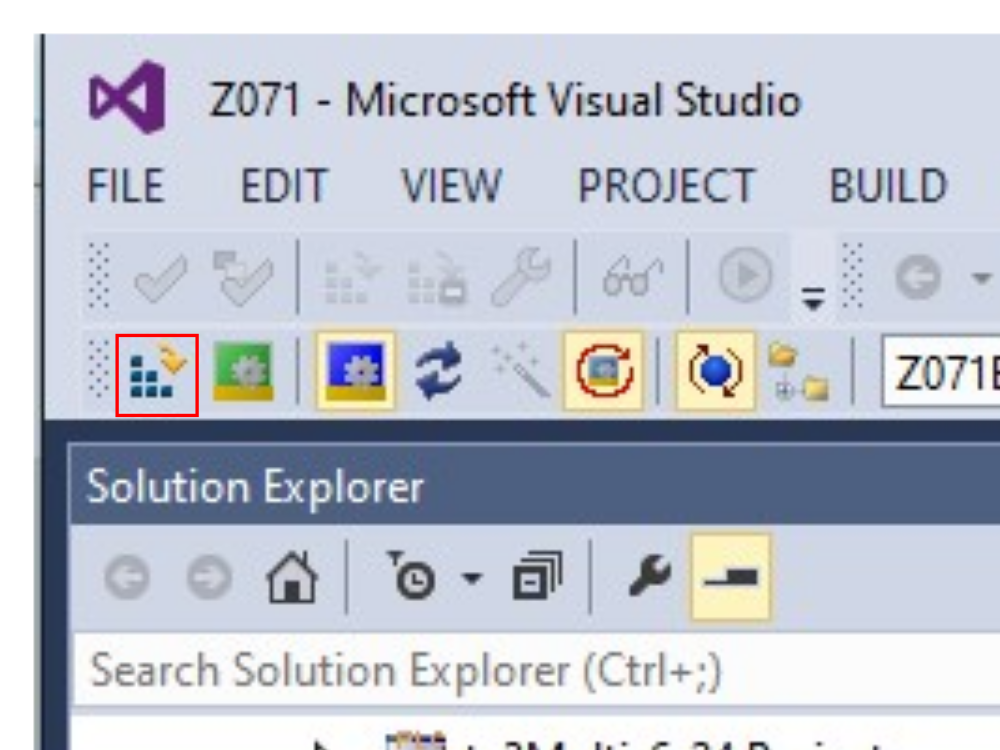
Étape 8 - Scan for Devices
- Expand IO
- Right click on devices, Scan
- Click OK on the Hint:
- Untick RT-Ethernet
- Untick COM-Port
- Just have the EtherCAT ports
- Scan for boxes - Yes
- If there is a request for New Device Type, Click Apply to All, Click Yes


Étape 9 - Check EtherCAT validity
Check the Devices and boxes match the expected EtherCAT setupRepeat steps 7 and 8 until the physical network matches the scanned networkYou may need to Right Click->scan Boxes on the second device if the EtherCAT boxes do not appear
Étape 10 - Name all EtherCAT devices according to network
Click twice on each device (not double click) to enable the device to be renamed
rename to convention

Étape 11 - Map all IO References
Using the circuit diagrams, map all the IO ref numbers to the associated IO channels
- Double click a field-bus box or slice
- Ensure you can see the input / Output list (may need some screen resizing
- Double click an IO channel
- Enter the number in the search box
- Double click the associated IO Ref number from ibInputArray(inputs) or qbOutputArray(outputs)
Repeat for all IO
Étape 12 - Double check all IO references with someone else
Any mistakes made will save hours if spotted here
Étape 13 - Activate configuration
Étape 14 - Add Axis Task
A smooth setup will have detected the axes and added them under the MOTION tab already.
if not, an axis task may need to be added under the MOTION tree:
- Add New Item
- NC/PTP Configuration
- Leave the Name as default


Étape 15 - Add Axes
If the axes do not exist under MOTION->NC Task->Axes, add them
- Right Click Add axis
- Name to convention nn Axis
Repeat for each axis on machine
Axis naming and configuration for different machines can be found here


Étape 16 - Map Axes
- Double click an axis
- Settings tab
- Click Link To IO
- Connect to associated Drive
- Click Link to PLC
- Use the reference here to get the Axis Numbers
Repeat for each axis
Étape 17 - Install Drive Manager 2 Project
- Note which Device number has the drive in it
- Left-click on FILE. A new context menu open
- Move the mouse to Add.
- Left-click on New Project.
- Select TwinCAT Drive manager 2 on left
- Click on TwinCAT Drive manager 2 Project on right
- Save with filename "[BuildNo] Drive Manager" in the folder for the project (c:\TwinCAT\Stuga\[BuildNo])
- EtherCAT master will be the device that has the drive in from Step 1
- Leave the basic settings, click OK
- This should link up the drives set in previous steps to a Drive Manager project
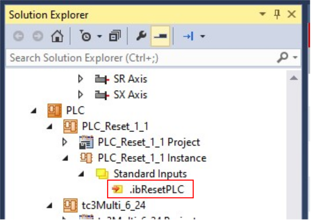
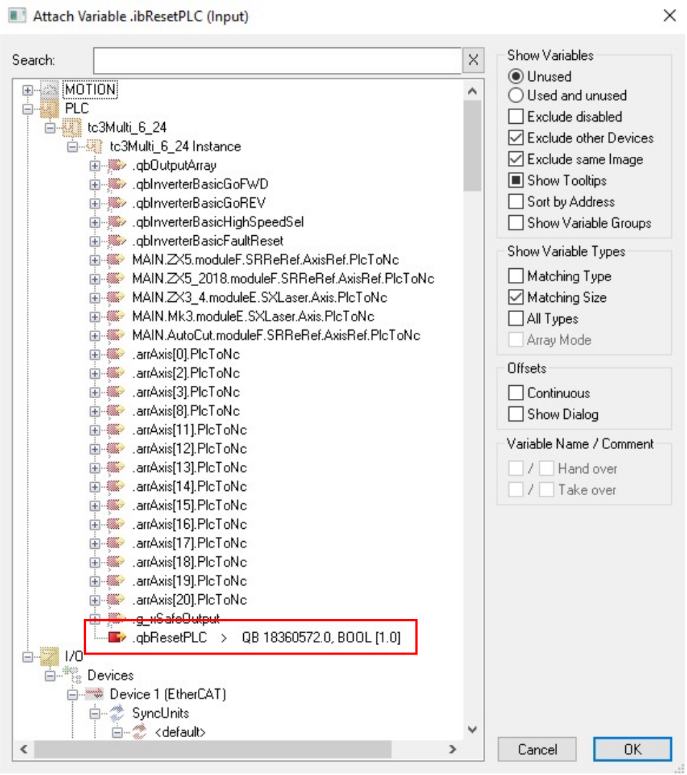
Étape 18 - Add PLC_Reset to tc3Multi Link
- Expand PLC_Reset Instance to get to ibResetPLC
- Double Click ibResetPLC to open the properties
- Link to qbResetPLC (this is very far down the list)
- Activate configuration
Draft
 Français
 English
 Deutsch
 Español
 Italiano
 Português