Introduction to the Autocut
Introduction
The Stuga Autocut is a PC compatible, computer controlled sawing centre capable of cutting a range of PVC-u profiles to length. The saw can cut square, mitred and arrow-head cuts on any profile, with the minimum of setting up.
Using the supplied keypad, a cutting list of up to 499 bars of up to 20 segments each can be entered into the computer's memory. Operator-free cutting of the list can then take place using the automatic infeed table. Alternatively, offcuts and spare lengths can be used and loaded manually.
Cutting lists can be prepared off-line on any standard office PC and also loaded into the computer's memory. This allows data entry whilst the centre is working, eliminating machine down-time.
Electrical
The control system is based around an industrial PC Card. This card controls all the machine functions, input, output and motion control. There is a keyboard for operator input, a VDU for viewing machine state, instructions and editing cutting lists.
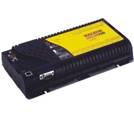
Motion Control, Inputs and outputs are controlled via a Baldor / ABB Nextmove ESB card. This is a programmable device that handles the sequencing of the machine and drives the pusher arm to the correct positions.
The unit handles 8 outputs and 12 inputs. Further IO is "extended" with the addition of a IO expansion slices on a CAN bus.
The pusher arm is driven by a Servo Motor via a Servo Drive.
On / Off Circuit
The circuit diagram for the on / off circuit is drawing number https://stuga.dokit.app/wiki/D4361_Saw_24v_AC_Circuit.
The ‘ON’ switch energises the coil of the main contactor, KM1, which pulls in the normally open contact, labelled 13-14. This latches on KM1 until ‘OFF’ is pressed, de-energising the coil. Obviously, power to energise the coil is not switched through KM1, hence transformer X1 is supplied directly from mains, switched only by the isolator.
X1 supplies both 24V ac (the contactor supply) and 110V ac (power supplies, fans, etc.), yet only 24V should be supplied all the time. For this reason, the 110V supply is switched through auxiliary contacts attached to KM1.
This can be seen in https://stuga.dokit.app/wiki/D4360_Power_Circuit
Emergency Stop Circuit
The ES Circuit has been updated to include a special emergency stop relay. This unit brings the machine into line with the European Standard PR EN 954 - 1 for the design of fail-safe control circuits. If any of the ES buttons are pressed, this relay trips and switches off mains to the saw motor, conveyor and extractor. It contains multiple sets of contacts, so there is no risk of the contacts welding.
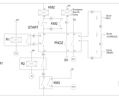
A diagram of the circuit is shown of Drg No 4361. Here it is seen that the ES circuit is a loop including 3 NC Stop buttons. Any of these will trip the PNOZ Relay, signaling the computer via X10, and switching the saw motor off via contact 33-34. The PNOZ is only reset after an on / off signal from the computer (Y12) via Relay R1.
Guard Circuit
The Guard Circuit has also been updated to include an interlocking system on the guard doors. This effectively prevents the doors being opened whilst the blade is spinning. The circuit itself is quite simple and can be seen on Drg No 4361. All 3 doors, Rear, Top and Front must be closed to energise KM3. KM3 signals the computer via X16, and also energises the saw motor contactor, KM2.
It is mechanically impossible to open the top and rear doors without first opening the front door. The front door is only opened via the guard interlock, energised with an output (Y4) from the computer, making it impossible to open the doors without the computer’s permission.
Included in the computer program is a time delay on opening the door. The delay is set for 60 seconds after the saw blade has finished rotating to give it ample time to stop.
Saw Motor Circuit
The saw motor contactor, KM2, can only be energised if four conditions are met:
- The ES relay has not been tripped.
- The computer’s permission is given - ‘Saw Motor On’ relay (R2) is on, output Y2.
- The guards are all closed.
- The START button is pressed and KM2 is latched.
This gives a very safe circuit, as the saw motor is not controlled directly from one single source.
Draft


 Français
 English
 Deutsch
 Español
 Italiano
 Português