Upgrade Blower to remove excess swarf when Top double plunge spindle is in operation
Sommaire
- 1 Introduction
- 2 Étape 1 - Assemble Valve and fittings
- 3 Étape 2 - Position Valve bracket and drill
- 4 Étape 3 - Connect 8mm blue feed tubing
- 5 Étape 4 - Trunking lids and lower swarf chute
- 6 Étape 5 - Connect Y285 pilot to valve bank
- 7 Étape 6 - Connect blower feed
- 8 Étape 7 - Refit all guards and trunking lids
- 9 Étape 8 - Route 6mm tubing through energy chain
- 10 Étape 9 - Drill access hole in tool break sensor plate
- 11 Étape 10 - Create blower pipe
- 12 Étape 11 - Fit blower pipe
- 13 Étape 12 - Finalise top tubing connections
- 14 Étape 13 - Secure and position copper blower line
- 15 Commentaires
Introduction
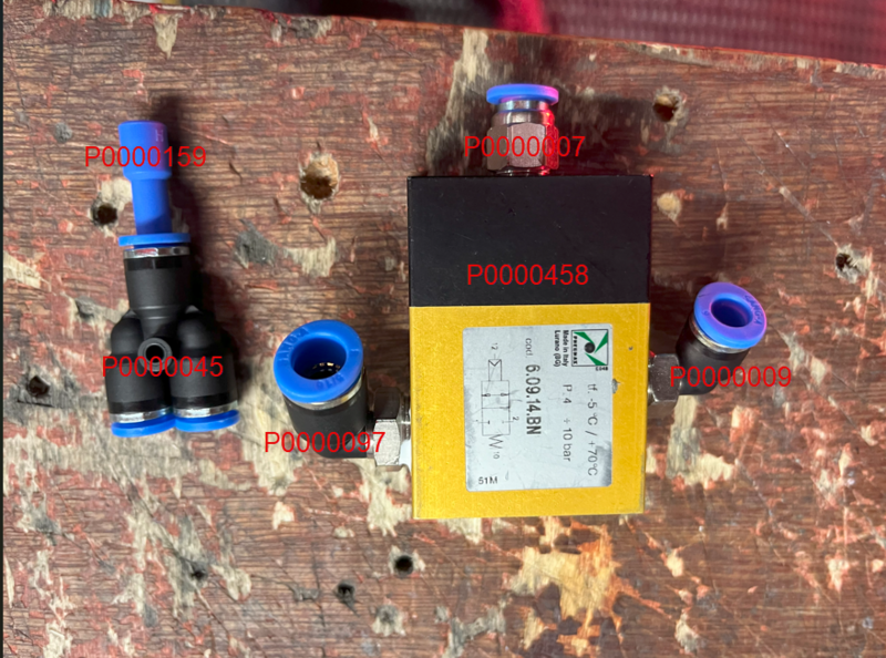
Component List
M0001083 6mm copper tubing x 0.5 mtr
P0000160 6mm inline flow reg x 1
P0000458 pilot valve x 1
P0000075 8mm Y connector x 1
P0000046 6mm y connector x 1
P0000159 6mm Blank x 1
P0000284 6mm elbow tube connector x 1
P0000007 6mm 1/8 straight connector x 1
P0000009 6mm 1/4 elbow connector x 1
P0000097 8mm 1/4 elbow connector x 1
P000005 6mm black tubing x 7
P0000365 8mm blue tubing x 1
D0001933 Single valve bracket x 1
F0000254 M5 x 12 socket cap x 2
F0000159 M5 A form washer x 2Étape 2 - Position Valve bracket and drill
1 Position valve bracket approximately as shown
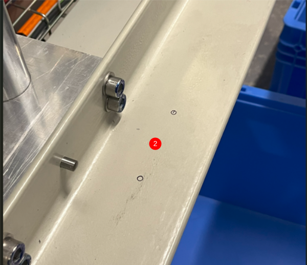
2 Mark holes through bracket, Drill and tap through marked holes to M5
Étape 3 - Connect 8mm blue feed tubing
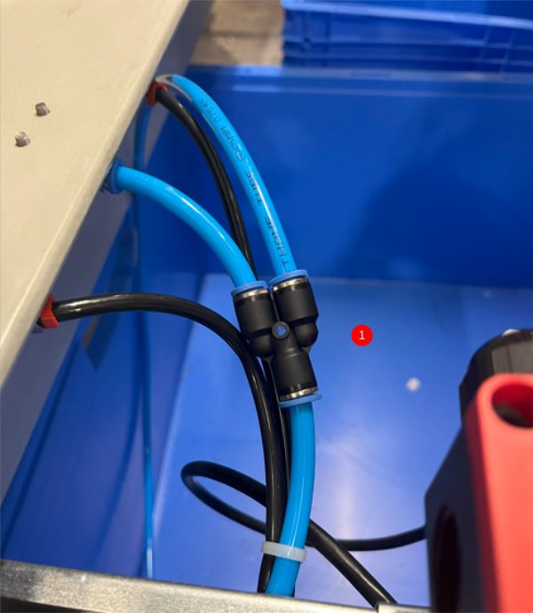
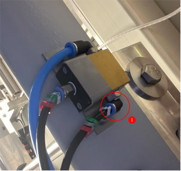
1 Use 8mm Y connector to feed 8mm blue tubing from original 8mm blue pipe feeding V notch cut valve
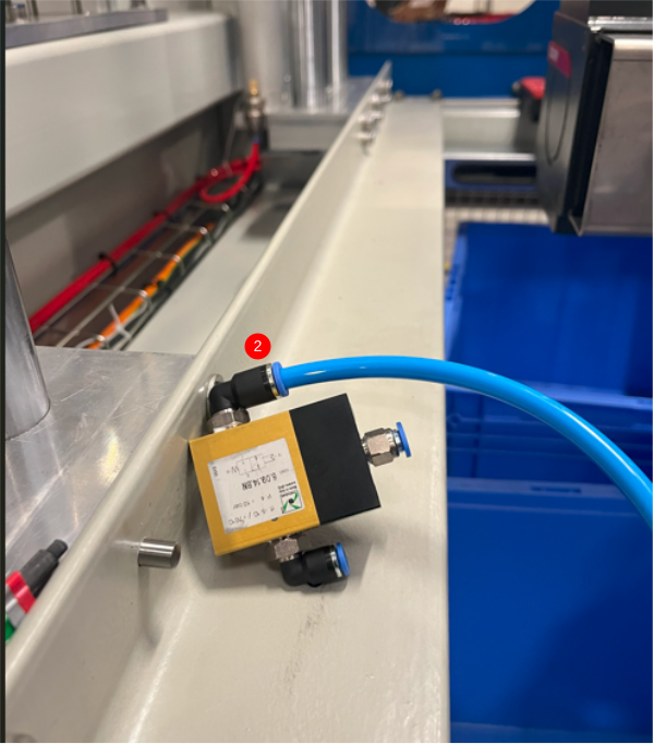
2 Connect to shown port on valve
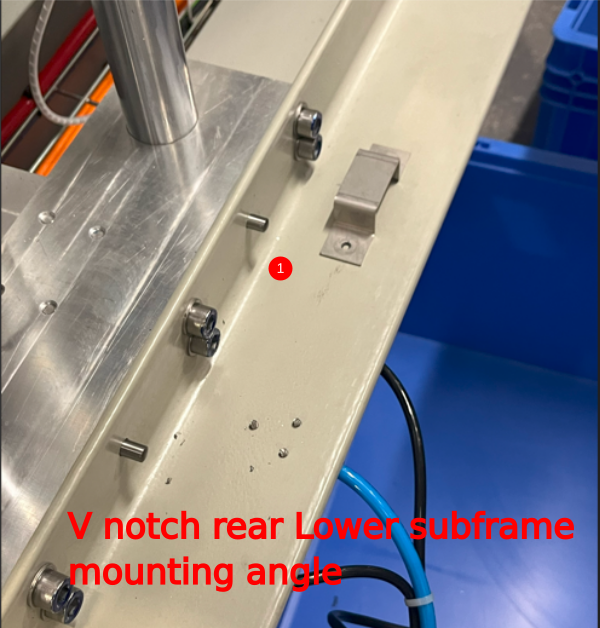
3 Fit valve with mounting bracket to underside on angle plate, using 2 off M5 x 12 socket caps and 2 off A form washers to fix
Étape 4 - Trunking lids and lower swarf chute
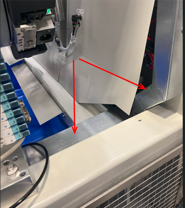
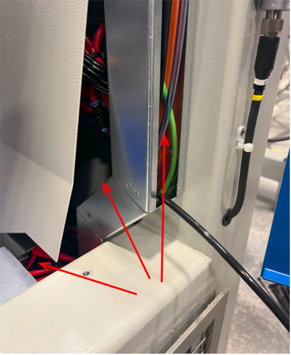
lower trunking lids and lower chute panel may require removing to install following pipework.
Étape 5 - Connect Y285 pilot to valve bank
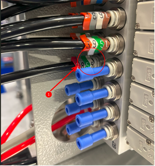
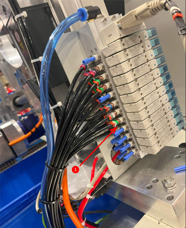
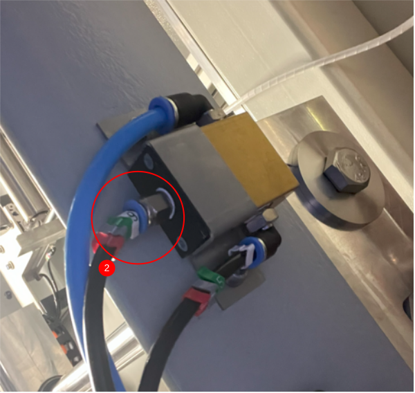
1 Remove fitted P0000159 6mm blank from indicated port on main valve bank and connect 6mm black tubing , route through trunking and exit next to pilot valve
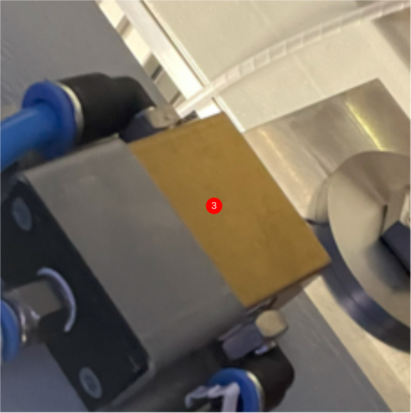
2 Connect to port shown on pilot valve
Étape 6 - Connect blower feed
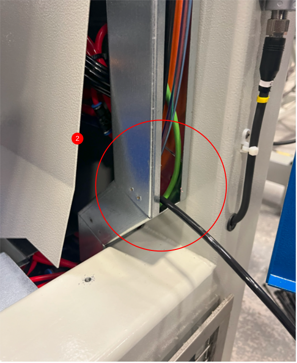
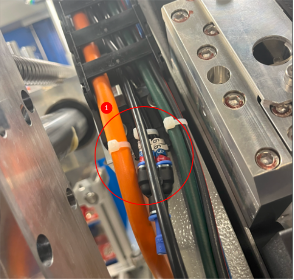
1 Connect 5 meter length of 6mm tubing to port shown on pilot valve and route into trunking at the same point as previous fitted tubing
2 Route pipe to point shown
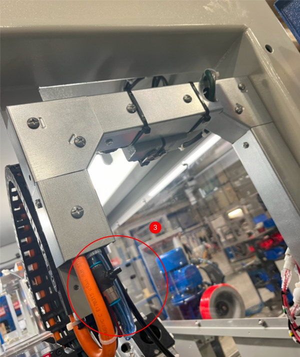
3 Continue routing to trunking exit point
Étape 7 - Refit all guards and trunking lids
Refit all trunking lids and swarf chutes , and internal connections are now complete
Étape 8 - Route 6mm tubing through energy chain
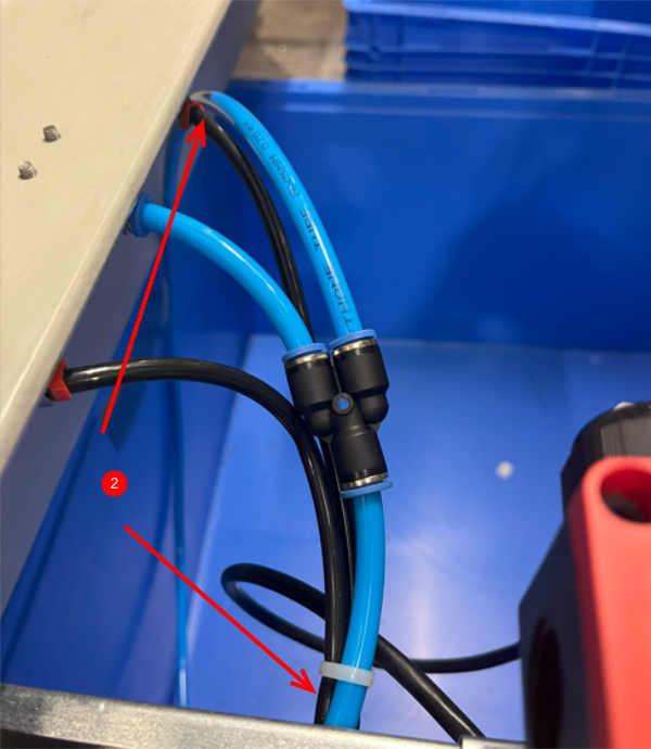
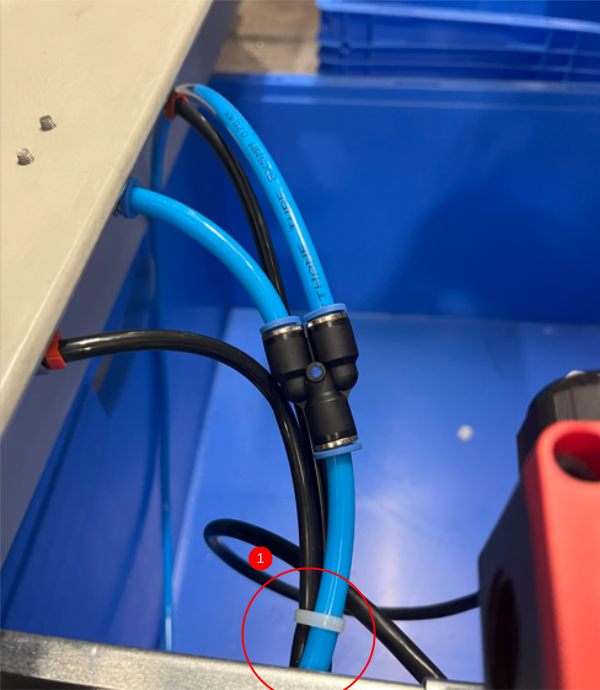
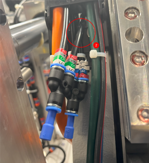
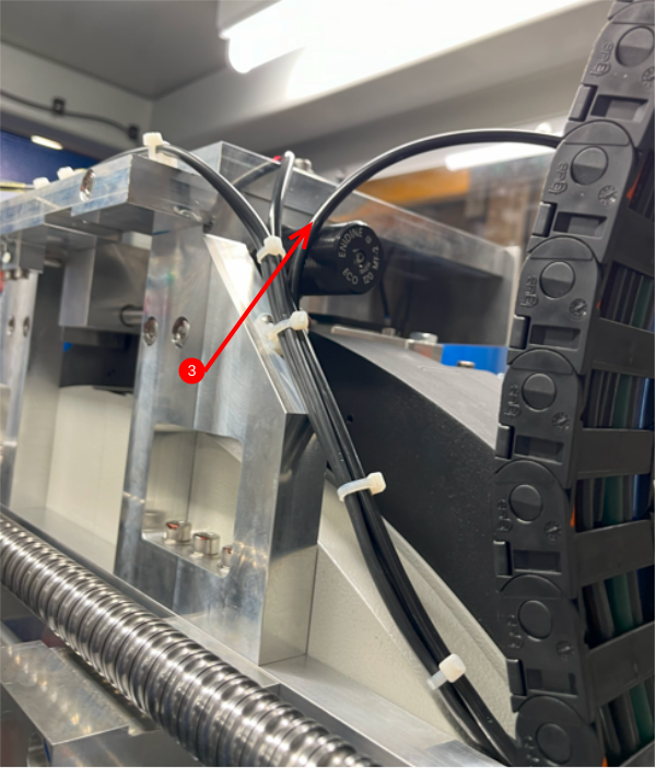
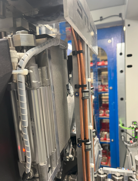
1 Route 6mm tubing through Y axis energy chain as shown
2 Fit 6mm y connector, and route additional 6mm tubing from Y connector as shown ( This y connector is fitted to stop pipe crimping on energy chain full movement
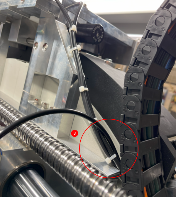
3 Tie new 6mm tubing to original loom exiting energy chain up to Tool break sensor assembly
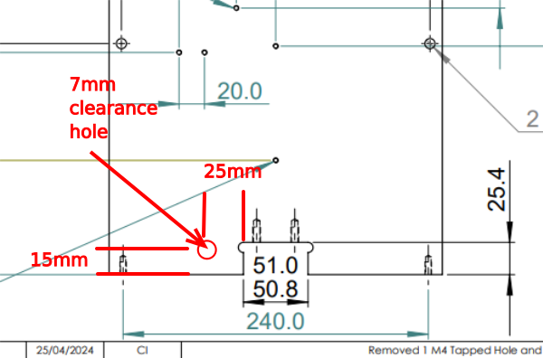
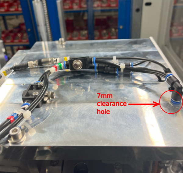
Étape 9 - Drill access hole in tool break sensor plate
Drill 7mm hole in D0001962 to dimensions shown. These are approximate dimensions for ease of fitting -+ 5mm
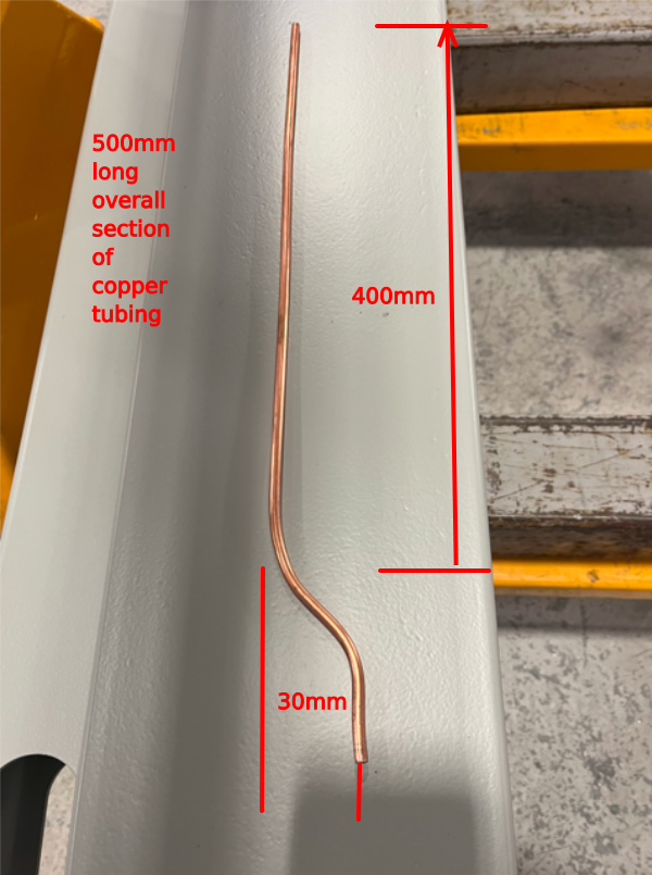
Étape 10 - Create blower pipe
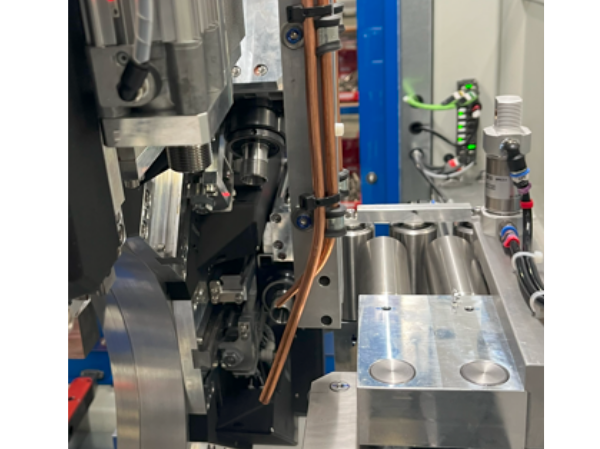
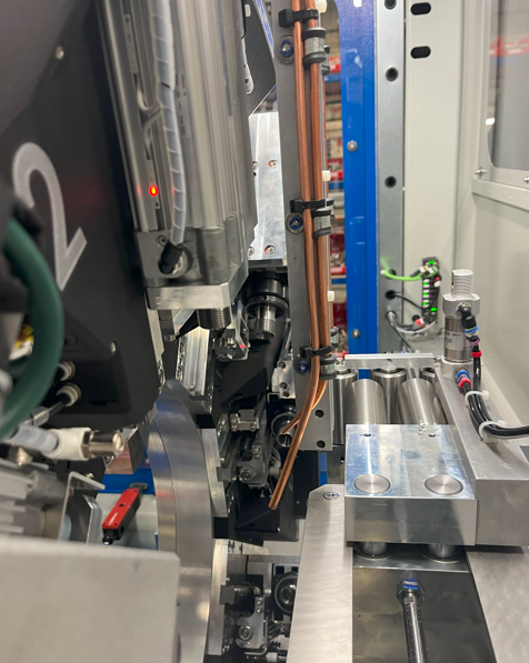
Manipulate 6mm copper pipe as shown , approximately form and finalise on fitting
Étape 11 - Fit blower pipe
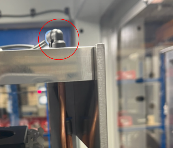
Insert copper pipe into drilled hole and hold in place with 6mm elbow tube tube fitting
Étape 12 - Finalise top tubing connections
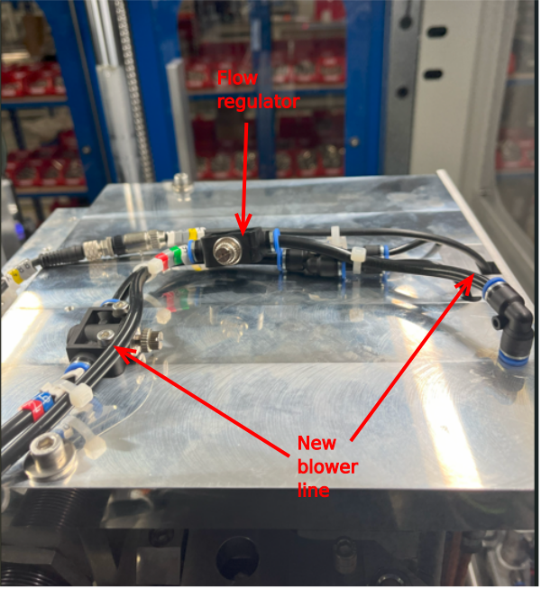
Connect top tubing section as shown, ensuring Flow restrictor is added to the line and correctly orientated to allow flow regulation when adjusted
(this can be tested once functioning )
Secure new tubing to original loom with tie wraps
Étape 13 - Secure and position copper blower line
Secure copper blower line to original tool break sensor blower as shown. Use Tie wraps to secure
Position end as shown , until function testing in operation, where blower end should be positioned for optimum swarf clearance when routing
Draft
 Français
 English
 Deutsch
 Español
 Italiano
 Português