Installation of wiring loom and captivating spindle bases
Sommaire
- 1 Introduction
- 2 Étape 1 - Quality
- 3 Étape 2 - Quality Check
- 4 Étape 3 - Start Wiring loom installation
- 5 Étape 4 - Fit spindle plate 6
- 6 Étape 5 - Fit Spindle plate 5
- 7 Étape 6 - Fit Spindle plate 4
- 8 Étape 7 - Fit Spindle plate 3
- 9 Étape 8 - Fit Spindle plate 2
- 10 Étape 9 - Fit Spindle plate 1
- 11 Étape 10 - Fit Spindle plate 8
- 12 Étape 11 - Fit Spindle plate 7
- 13 Commentaires
Introduction
Tools Required
Standard hex key set
Ball pein hammer
6mm drift/punch
Drill driver
6mm hex drill attachment
Parts Required
D00000291 spindle plate x 8
M0000025 Ident numbers x 1
D0007703 r stop pin x 1
D0007990 cylinder anchor x 1
D0007777 Trunking backplate x 2Étape 1 - Quality
All bolts to have Loctite 243 adhesive applied unless otherwise stated
All bolts to be pen marked once adhesive applied and correct tension added
Étape 2 - Quality Check
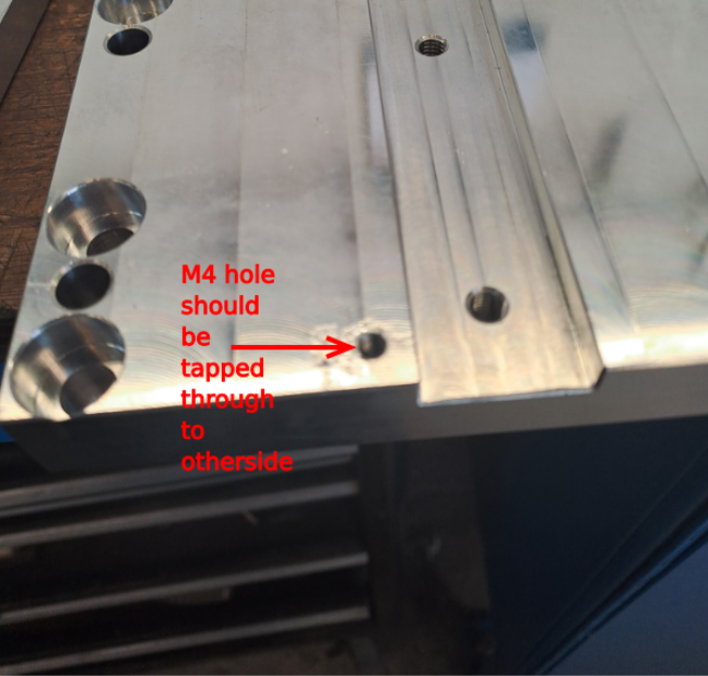
Check D0000291 spindle base has M4 hole tapped all the way through the plate. Rework if not
Étape 3 - Start Wiring loom installation
1 Segregate cables and 6mm blue pipe as shown
2 Use pre made cable identified as 6 and 7 and lay between 2 points shown
Étape 4 - Fit spindle plate 6
1 Fit D0000291 spindle plate and lightly secure with 2 off M8 x 25 socket caps in opposing corners
2 Fit M0000025 number ident (number 6)
Étape 5 - Fit Spindle plate 5
1 Retrieve pre marked ethercat cable marked SP5-SP6
2 Retrieve pre marked power cable marked 5-6
3 Lay both cables into chamber to the left of previous fitted plate
Ensure SP5 and 5 exit to left
Ensure SP6 and 6 exit to the right
4 Fit D0000291 spindle plate and lightly secure with 2 off M8 x 25 socket caps
5 Fit M0000025 ident number to spindle plate (number 5)
Étape 6 - Fit Spindle plate 4
1 Retrieve pre marked ethercat cable marked SP4-SP5
2 Retrieve pre marked power cable marked 4-5
3 Lay both cables into chamber to the left of previous fitted plate
Ensure SP4 and 4 exit to left
Ensure SP5 and 5 exit to the right
4 Fit D0000291 spindle plate and lightly secure with 2 off M8 x 25 socket caps
5 Fit M0000025 ident number to spindle plate (number 4)
Étape 7 - Fit Spindle plate 3
1 Retrieve pre marked ethercat cable marked SP3-SP4
2 Retrieve pre marked power cable marked 3-4
3 Lay both cables into chamber to the left of previous fitted plate
Ensure SP3 and 3 exit to left
Ensure SP4 and 4 exit to the right
4 Fit D0000291 spindle plate and lightly secure with 2 off M8 x 25 socket caps
5 Fit M0000025 ident number to spindle plate (number 3)
Étape 8 - Fit Spindle plate 2
1 Retrieve pre marked ethercat cable marked SP2-SP3
2 Retrieve pre marked power cable marked 2-3
3 Lay both cables into chamber to the left of previous fitted plate
Ensure SP2 and 2 exit to left
Ensure SP3 and 3 exit to the right
4 Fit D0000291 spindle plate and lightly secure with 2 off M8 x 25 socket caps
5 Fit M0000025 ident number to spindle plate (number 2)
Étape 9 - Fit Spindle plate 1
1 Retrieve pre marked ethercat cable marked SP1-SP2
2 Retrieve pre marked power cable marked 1-2
3 Lay both cables into chamber to the left of previous fitted plate
Ensure SP1 and 1 exit to left
Ensure SP2 and 2 exit to the right
4 Fit D0000291 spindle plate and lightly secure with 2 off M8 x 25 socket caps
5 Fit M0000025 ident number to spindle plate (number 1)
Étape 10 - Fit Spindle plate 8
1 Retrieve pre marked ethercat cable marked SP8-SP1
2 Retrieve pre marked power cable marked 8-1
3 Lay both cables into chamber to the left of previous fitted plate
Ensure SP8 and 8 exit to left
Ensure SP1 and 1 exit to the right
4 Fit D0000291 spindle plate and lightly secure with 2 off M8 x 25 socket caps
5 Fit M0000025 ident number to spindle plate (number 8)
Étape 11 - Fit Spindle plate 7
1 Retrieve pre marked ethercat cable marked SP7-SP8
2 Retrieve pre marked power cable marked 7-8
3 Lay both cables into chamber to the left of previous fitted plate
Ensure SP7 and 7 exit to left
Ensure SP8 and 8 exit to the right
4 Fit D0000291 spindle plate and lightly secure with 2 off M8 x 25 socket caps
5 Fit M0000025 ident number to spindle plate (number 7)
Draft


 Français
 English
 Deutsch
 Español
 Italiano
 Português