Bench assembly details for Saw top Hood

Difficulté
Moyen
Durée
1 minute(s)
Introduction
Introduction
Tools Required
Standard hex key set
Standard spanner set
Standard Hss drill set
Standard tap set
Acoustic foam cutting board and straight edge
Utility Blade
Parts Required
Pre wired light, beacon and network cable from electrical department
C0001152 Camera: HikVision DS-2CD2343G0-I-2.8mm x 1
C0001239 Micro SD Card 32Gb Class 10 x 1
D0000770 Door Hinge (M0016) x 2
D0001877 Saw Top Door Mk4 x 1
D0004641 Hinge Pin Block (D7445) x 1
D0004642 Flap Counterbalance Bar x 1
D0004645 Safety Flap Hinge Pin x 1
D0004679 Flap Stiffening Bar x 1
D0004705 Flap Hinge Bar x 1
D0004747B top door screen x 1
D0004807 Flap x 1
D0007445 Hinge Pin Block OH (D4641) x 1
D0016251 Saw Hood Switch Mount Plate (Bernstein) x 1
E0000275 Button: Base Fixing 1 N/C x 1
E0001072 Emergency Stop Module Bevelled 1NO 1NC x 1
E0001569 Guard Lock Switch: Bernstein Radius Actuator (Key) x 1
H0004643 4mm Axxis Clear 145mm x 690mm x 1
M0000002 12mm Grey Acoustic Foam with Black PVC Facing x 1 (consumable stock )
M0000036 Sign - Ear Protection x 1
M0000048 Gas Spring 15mm x 100mm x 1
M0000539 Handle Black Nylon 200mm M8 Fixings x 1Étape 1 - Assembly safety flap
1 Ream 6mm holes indicated to ensure
2 Pins locate correctly
3 Drill flap to suit stiffening bar
4 Attach end brackets and stiffening bar using 4 off M5 x 16 socket caps and 4 off M5 A form washers and 2 off M5 x 12 socket caps and 2 off M5 penny washers
5 Insert 6mm rods and add 2 off M5 x 6 kcp grubscrew
6 Fit hazard tape to flap


Étape 2 - Assembly safety flap
L-R configuration of safety flap


Étape 3 - Fit safety flap to hood
1 Check Mounting blocks have pin fitted as shown. A pair is required (mirrored to each other )
If not modify M6 x 35 socket cap 2 off as follows
- Reduce thread length to 10mm
- Use studlock 270 and fit to block ensuring final tension
- Cut shank of socket cap down to 10mm protrusion and dress clean
2 Fit 1 off mounting block to point shown , using 2 off M5 x 16 socket countersunk s to fix. Ensure correct orientation of block and correct face has countersunk holes for fixing 3 Fit 2nd block to safety flap and fit to hood as shown . Use 2 off M5 x 16 socket caps and M5 penny washers to fix
4 Adjust 6mm pins to centralise flap and stop end float of assembly. Finalise 2 off M5 grubscrews


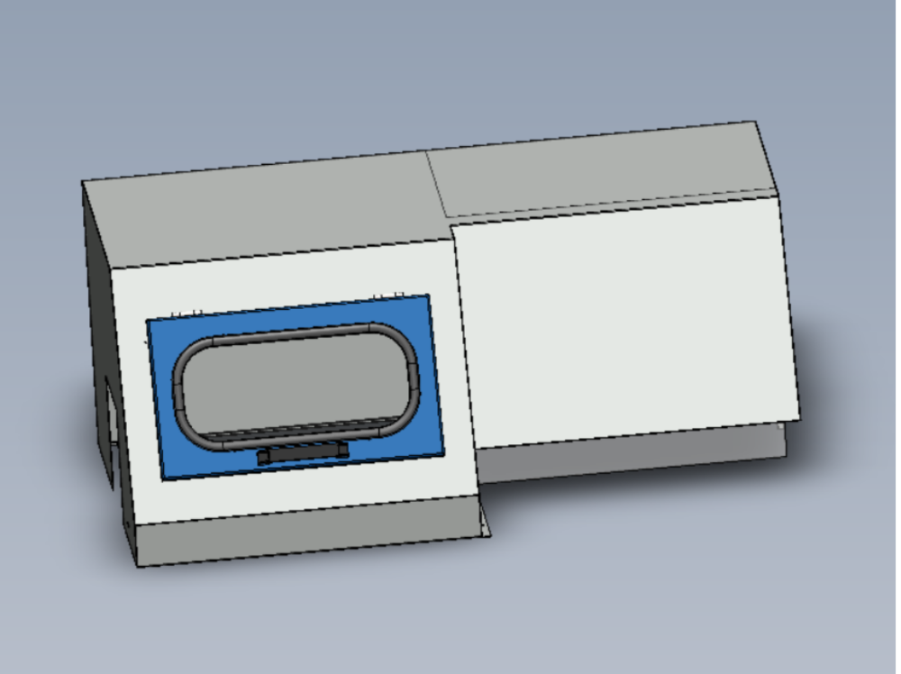
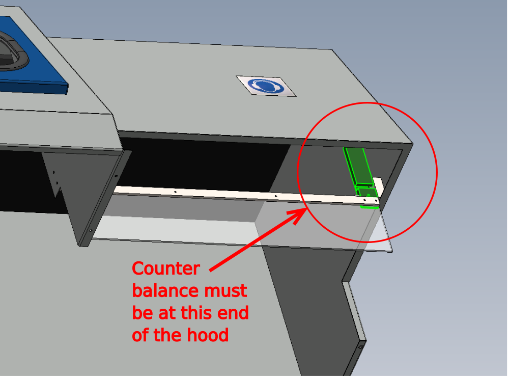
Étape 4 - Quality Check
There has been instances of the safety flap being fitted incorrectly and hindering saw operation.
To clarify correct position, larger counter balance on safety flap must be furthest away from saw head
Étape 5 - Fit trunking to rear
...ECR raised 21/11/23 to add M5 mounting holes for trunking onto hood. Until processed, add on assembly
Fit A0001098 37mm x 75mm trunking to rear of hood, secure with M5 x 10 button sockets and M5 penny washers
Provide drilling details for fixing

Étape 6 - Fit stickers to hood
All stickers must be applied wet to ensure no air bubbles are present
Use spray foam and squeegee to fit
1 Large clear STUGA sticker to top of hood. Stuga to read from front
2 Large clear STUGA sticker on rear of hood
3 Service sticker on rear of hood
4 Ambient temperature sticker to front of hood
5 Consumables sticker to front of hood
6 Ear defence sticker to front of hood


Draft
 Français
 English
 Deutsch
 Español
 Italiano
 Português