Instructions for refurbishment of R0000728 and R0000729 stroke assemblies using Kit R0000299

Difficulté
Difficile
Durée
3 heure(s)
Sommaire
- 1 Introduction
- 2 Étape 1 - Handing clarification
- 3 Étape 2 - Unless otherwise stated
- 4 Étape 3 - Disassembly
- 5 Étape 4 - Remove blade Guard
- 6 Étape 5 - Remove Blade
- 7 Étape 6 - Remove damper bridge
- 8 Étape 7 - Disconnect front blade assembly
- 9 Étape 8 - Extract front blade assembly
- 10 Étape 9 - Extract 2 off shafts
- 11 Étape 10 - Remove hard stop
- 12 Étape 11 - Remove motor assembly
- 13 Étape 12 - Remove Pinion bolt and shaft bolt
- 14 Étape 13 - Remove drive pinion
- 15 Étape 14 - Remove drive shaft
- 16 Étape 15 - Extract shaft from bearing housing
- 17 Étape 16 - Remove keys from shaft
- 18 Étape 17 - Disconnect bevel gear
- 19 Étape 18 - Remove bevel gear
- 20 Étape 19 - Use press to remove blade flange
- 21 Étape 20 - Remove bearing from housing
- 22 Étape 21 - Remove bearing housing
- 23 Étape 22 - Remove motor pinion housing
- 24 Étape 23 - Disposed parts not required
- 25 Étape 24 - Clean and degrease
- 26 Commentaires
Introduction
Assemblies fitted to MK1 ZX4 will require refurbishment at some point of life cycle.
The following instructions should be followed to ensure that correct assembly and setting are performed
Tools / consumables Required
Standard hex key set
Standard spanner set
Double pin saw flange spanner
Drifts and punches
Ballpein hammer
Soft hammer
Degreasing bath
Solvent Fe10
Loctite 243adhesive
Loctite 641 bearing fit
Thixotropic grease
Parts Required
Kit R0000299 containing
B0000043 Double Angular bearing 15 I?D 35 O?D 15.9 long rubber seal 3 x 2
B0000105 Double Angular Bearing 15 I/D 35 O/D 15.9 Long x 1
B0000335 3ph Brake motor 2 pole 3000rpm x 1
B0000380 Double Angular Bearing 25 I/D 52 O/D 20.6 Long + rubber seal x 2
D0000059 Damper Bridge x 1
D0000062 Damper Bridge Boss x 2
D0007730 ZX4 V Notch Mk1 Spindle Shaft x1
D0007867 Bevel Gear (Left) x 1
D0007868 Bevel Gear (Right ) x 1
D0007873 Motor Gear x 1
D0007874 Pinion Gear x 1
D0007875 Pinion Shaft x 1
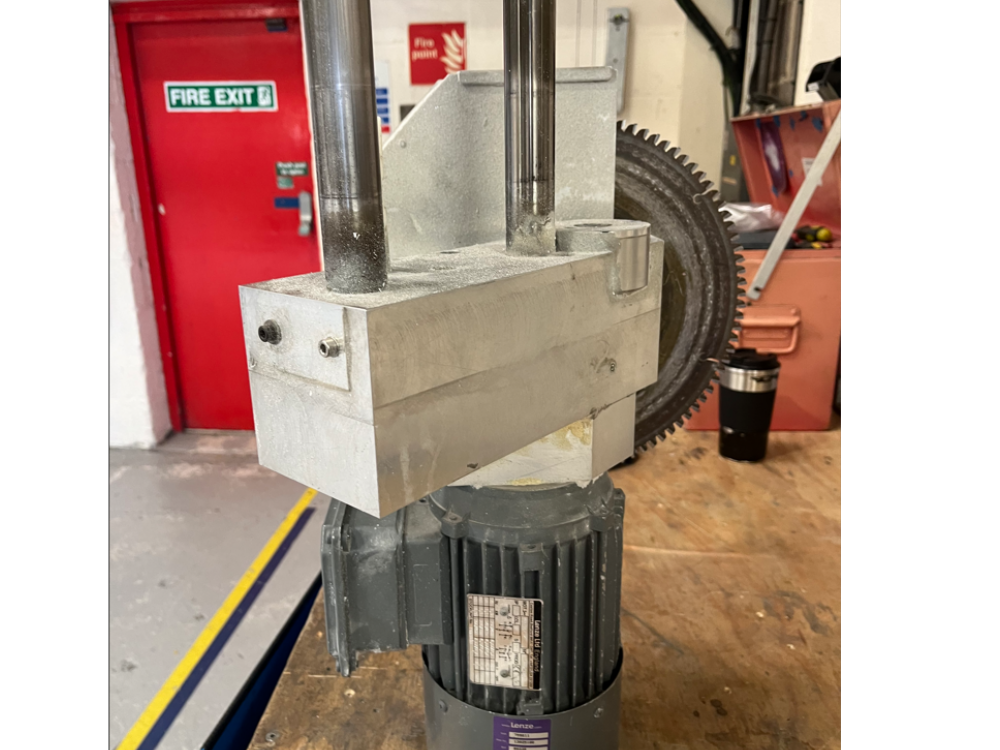
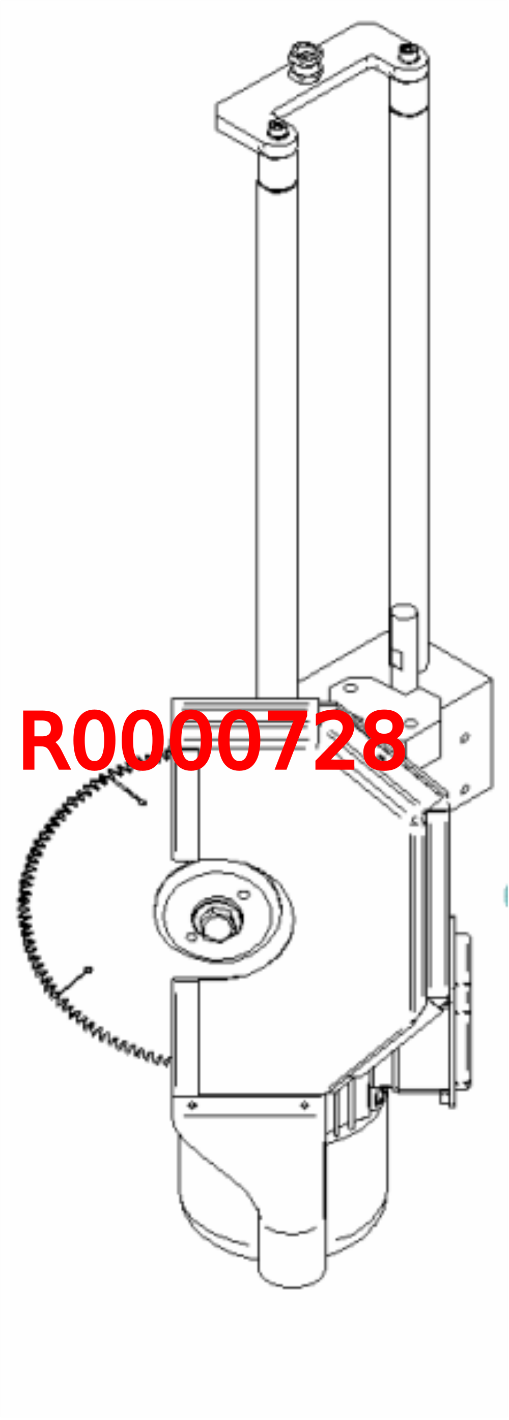
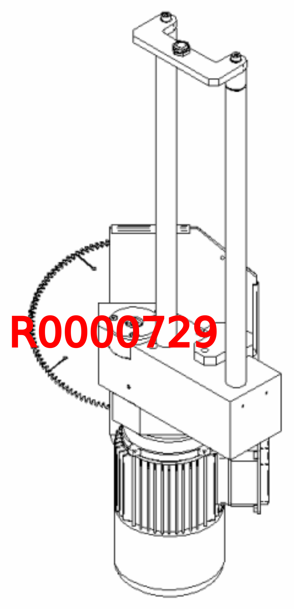
Étape 1 - Handing clarification
R0000728 and R0000729 are mirror images to each other
Please inspect pictures to clarify and confirm correct hand to be built
(Supplied unit to be refurbished will always be rebuilt as the same hand )
Étape 2 - Unless otherwise stated
Always use Loctite 243 on all fasteners fitted unless stated different
All bearings should be an acceptable fit, with Loctite 641 and FE10 solvent used if required
All fasteners should be marked once finalised

Étape 3 - Disassembly
The stroke assembly must be dismantled in the exact manner stated as many sections can only be removed once mating parts have been extracted
Please use the following steps accurately

Étape 4 - Remove blade Guard
Remove M5 socket cap and washer and slide off blade guard
Blade guard to be reused


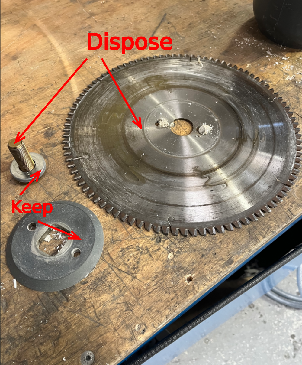
Étape 5 - Remove Blade
use 24mm ring spanner and saw blade pin spanner to remove blade from assembly
Dispose of saw blade and M16 bolt
Keep M16 Washer and blade flange for rebuid


Étape 6 - Remove damper bridge
Remove 2 off m8 fasteners to remove damper bridge and pillars
Dispose of all parts


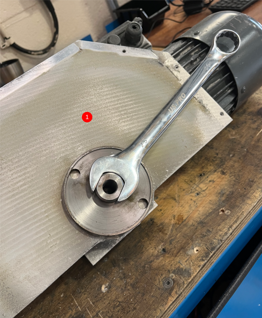
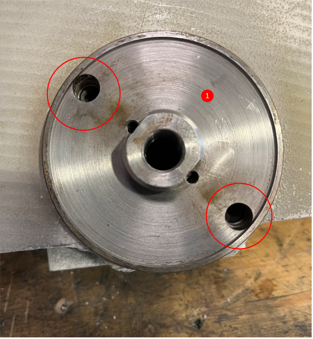
Étape 7 - Disconnect front blade assembly
1 Rotate blade flange with a 25mm spanner to align 2 off M6 cap heads through access holes
2 Remove 2 off m6 socket cap bolts
3 Rotate blade flange to align second set of M6 socket caps and remove
4 off in total M6 socket caps to be removed


Étape 8 - Extract front blade assembly
Front assembly can now be extracted from the main housing


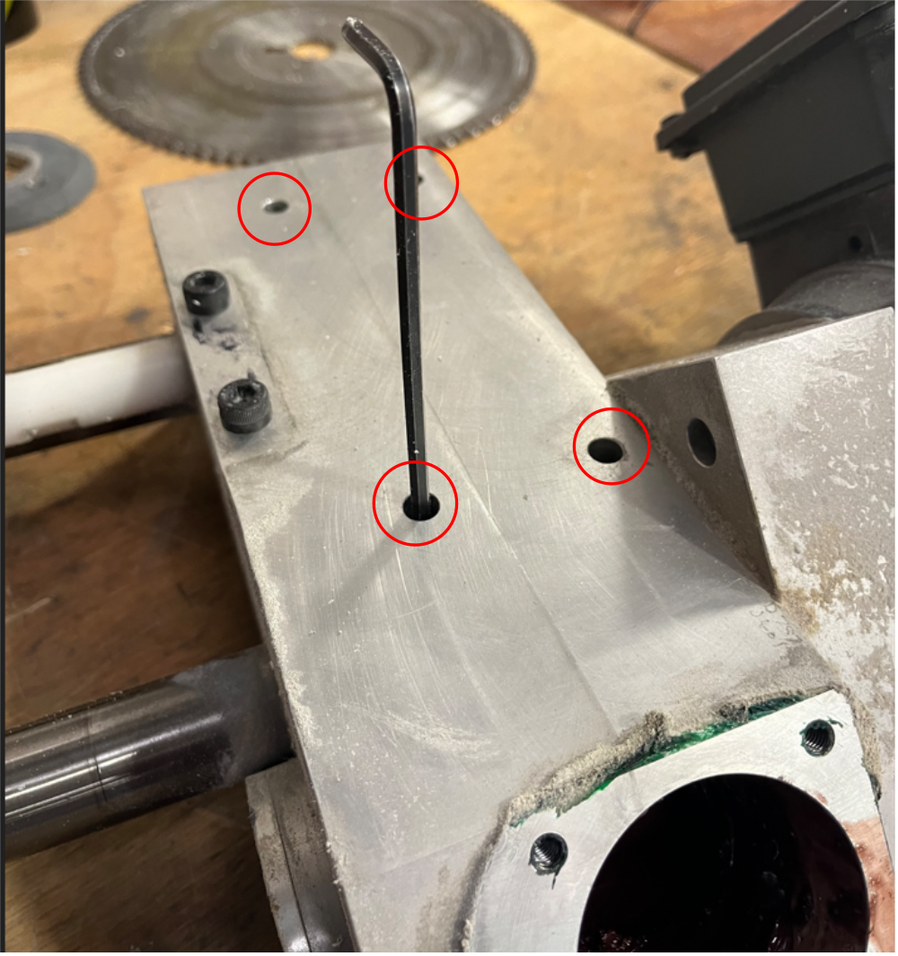
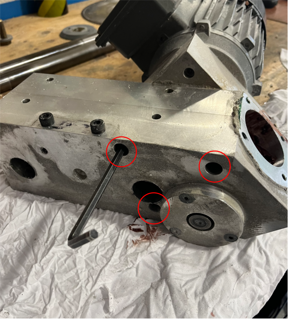
Étape 9 - Extract 2 off shafts
Remove 4 off M8 grubscrews indicated and extract 2 off hardened shafts from main body
Shafts to be refurbished

Étape 10 - Remove hard stop
Use 17mm spanner to remove hard stop as shown
Hard stop to be refurbished

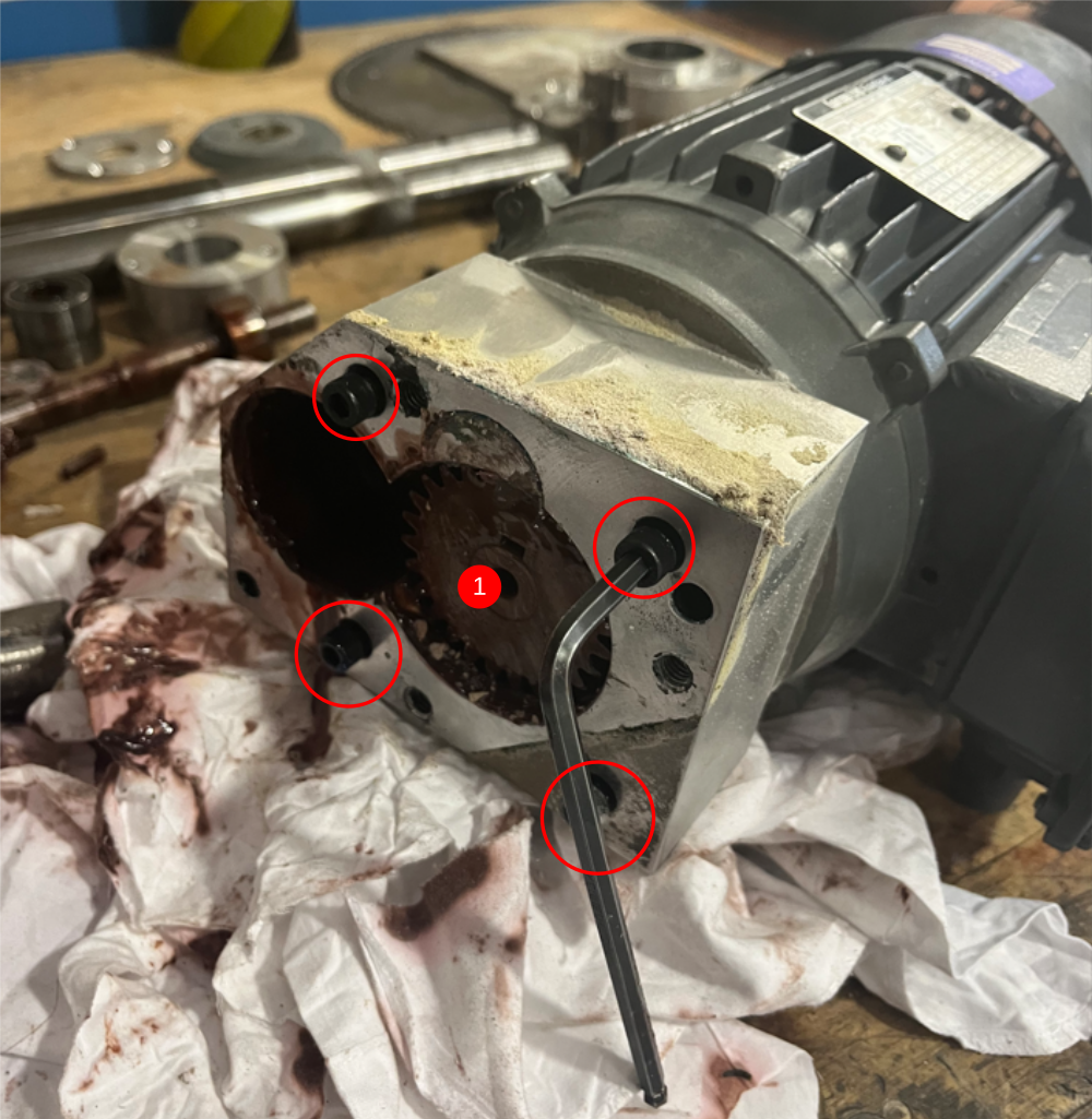
Étape 11 - Remove motor assembly
1 Remove 3 off M8 socket caps indicated
2 Separate as shown . Two components are doweled together, use caution to not damage any faces when separating two parts


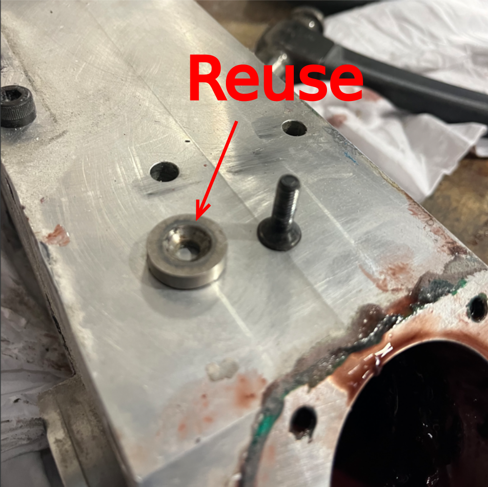
Étape 12 - Remove Pinion bolt and shaft bolt
Remove fasteners as shown
Machined washer to be reused


Étape 13 - Remove drive pinion
Raise pinion shown to allow blocks to be added beneath
Use drift to separate pinion from shaft
Dispose of pinion gear


Étape 14 - Remove drive shaft
1 Remove 3 off M6 countersunk bolts shown
2 Remove top cap and keep for refurbishment
3 drive shaft from base to extract assembly from housing


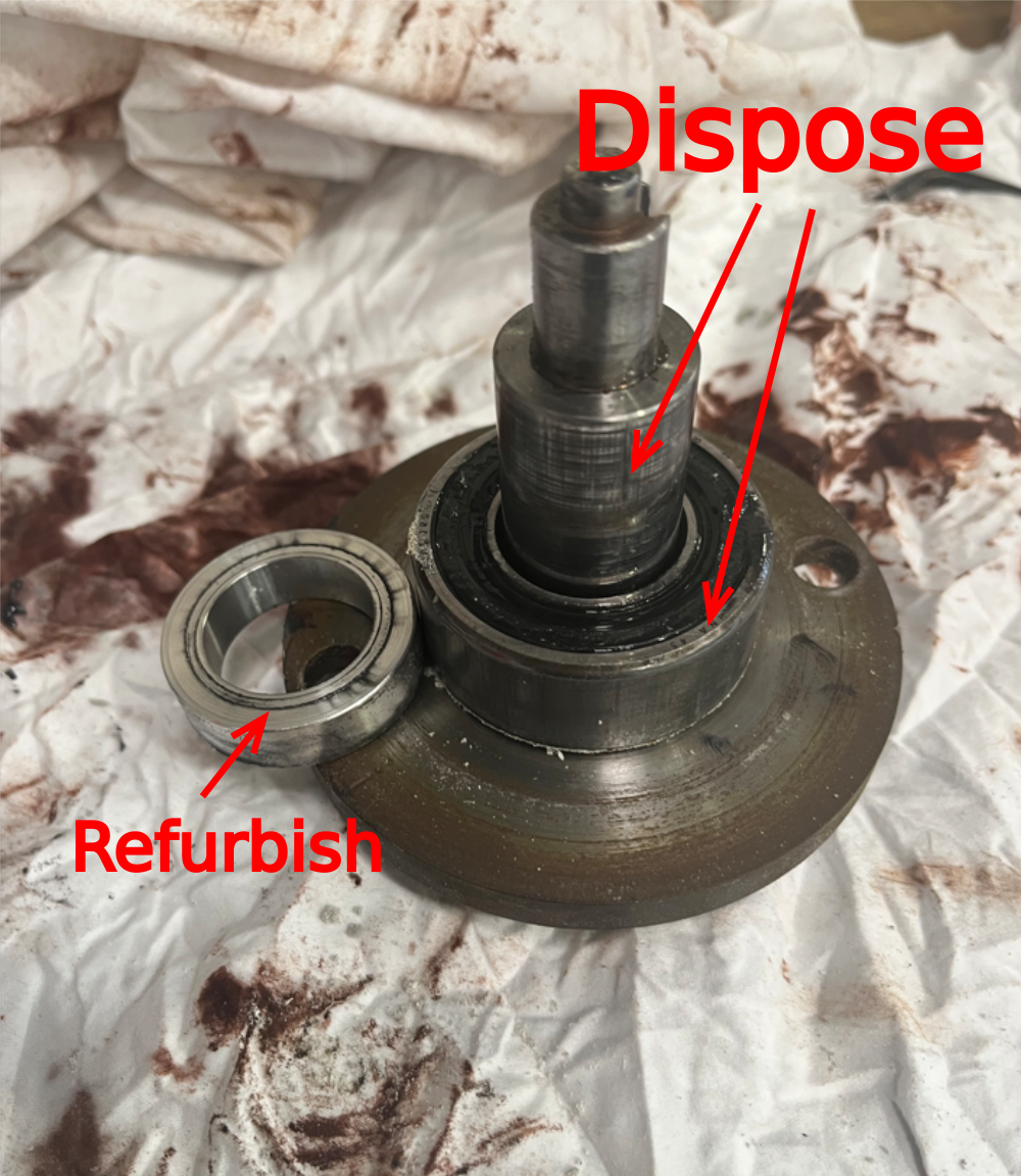
Étape 15 - Extract shaft from bearing housing
Extract shaft as shown, and remove bearings from housing
Dispose of bearings


Étape 16 - Remove keys from shaft
Remove two off keys from shaft to reuse and dispose f rest of components
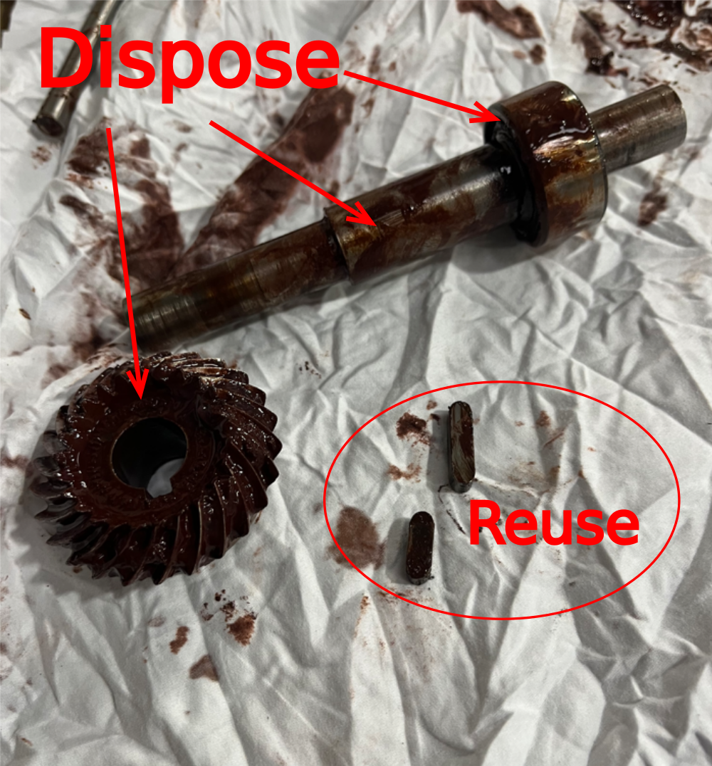
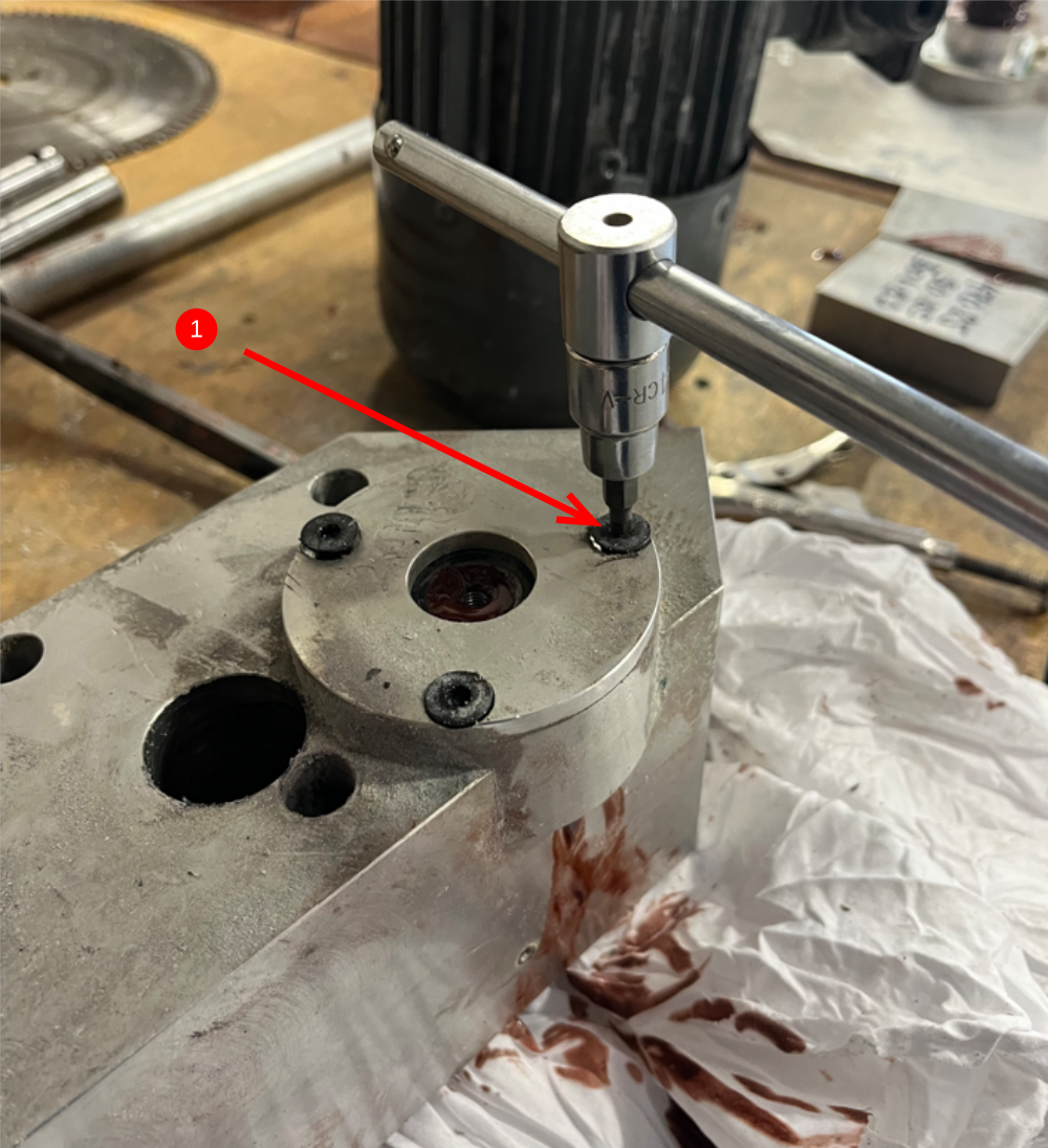
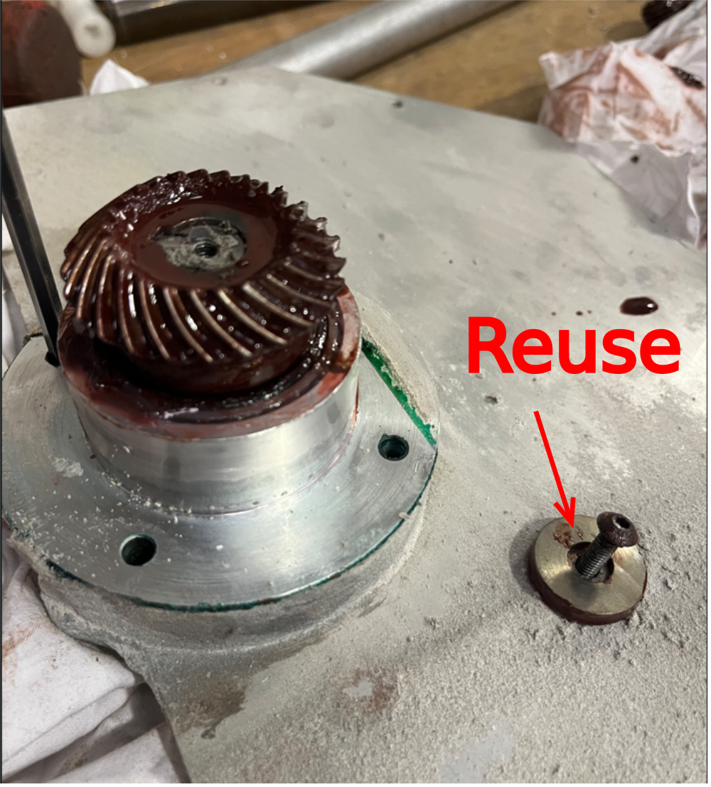
Étape 17 - Disconnect bevel gear
Lock drive flange as shown and remove M5 fastener on end of bevel gear
Machined washer to be reused


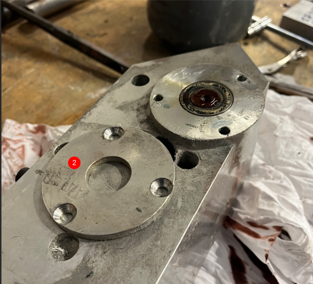
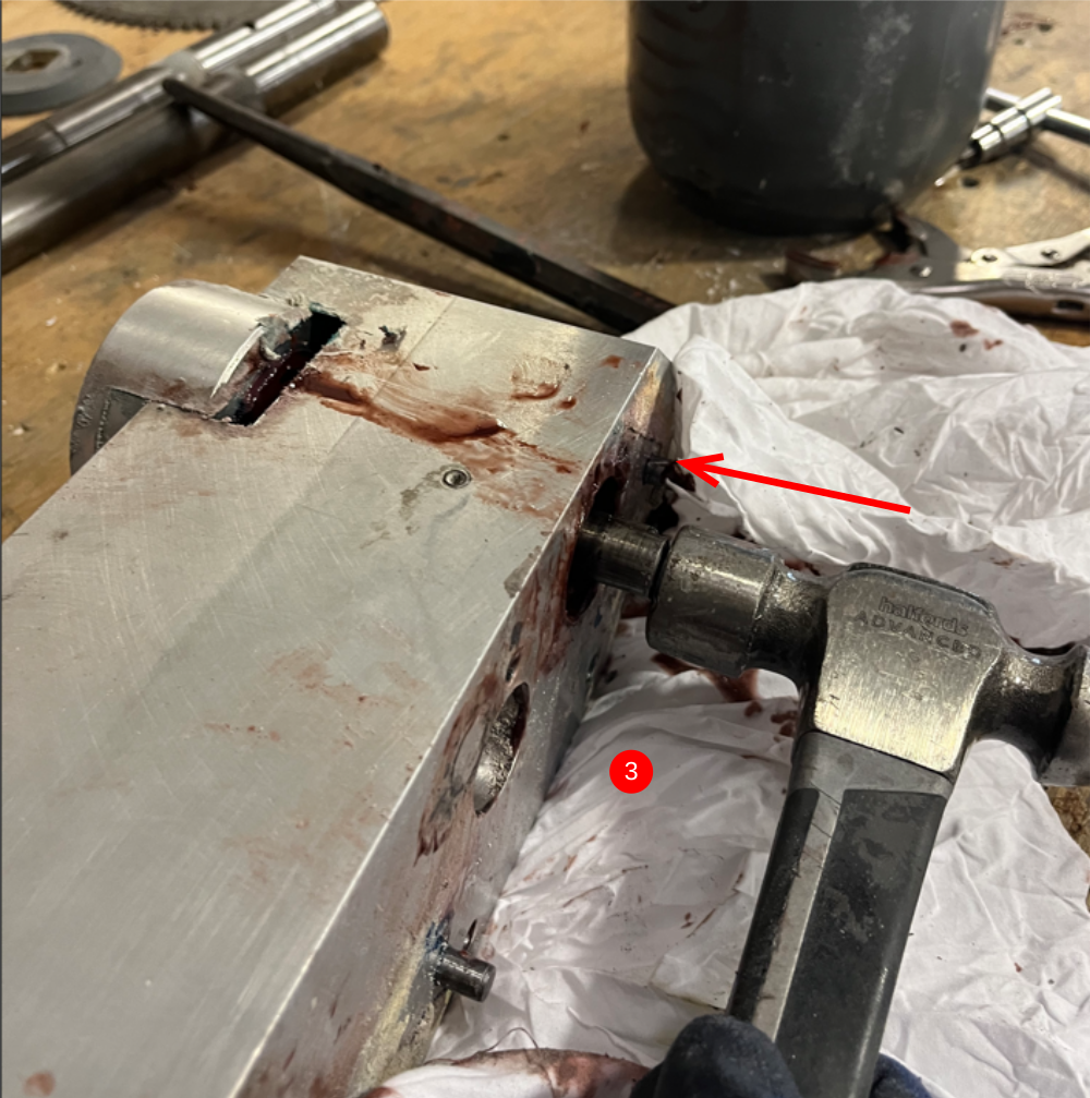
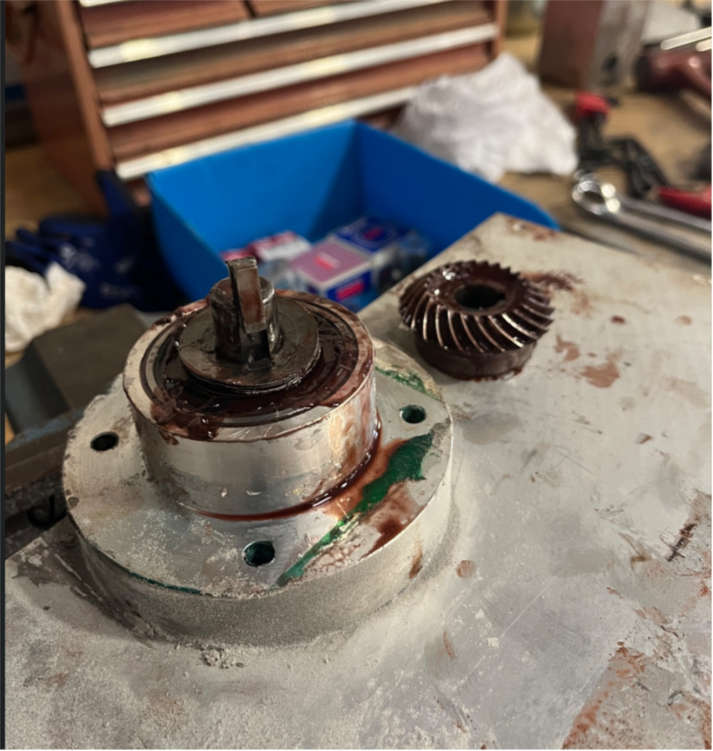
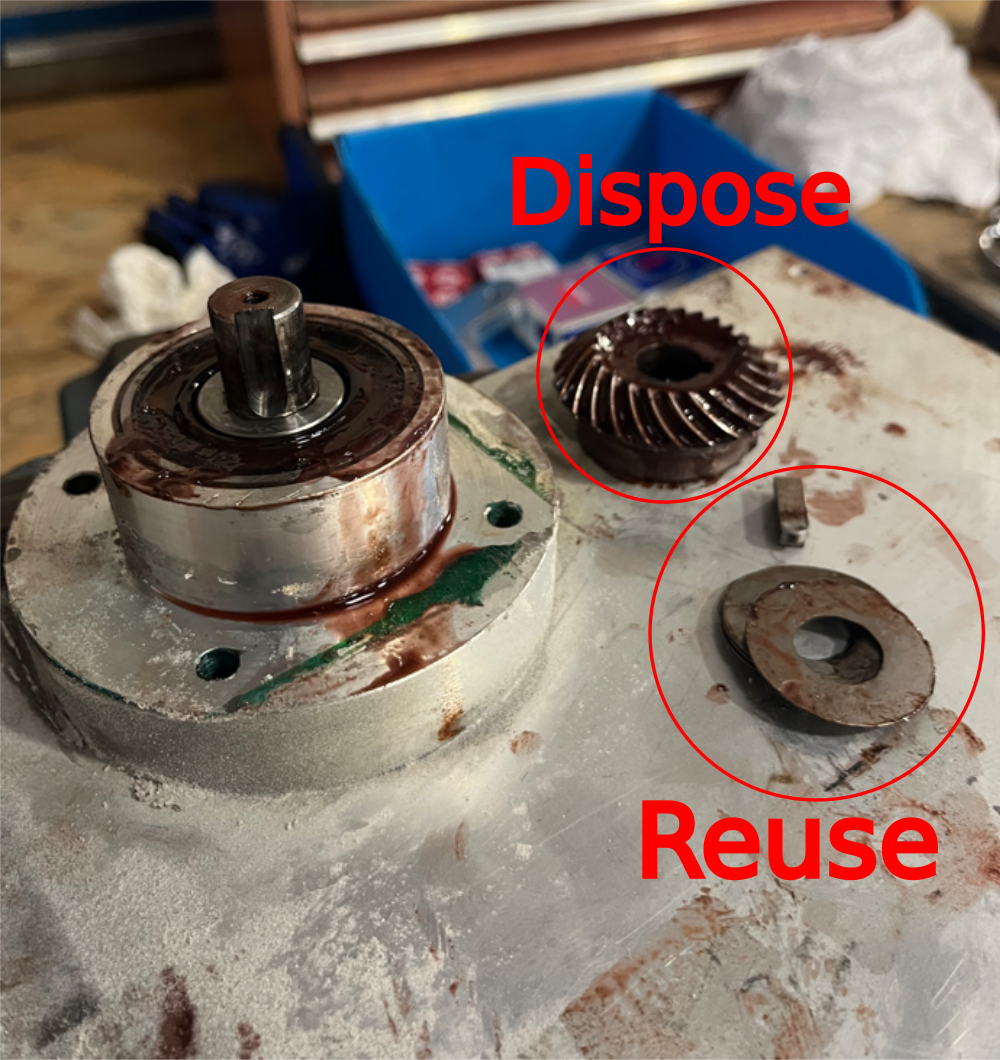
Étape 18 - Remove bevel gear
1 Use drift to move bevel gear enough to allow pry bars to be used underneath
2 Use pry bars to remove gear
3 Key and shim washers to be reused
Bevel gear to be disposed


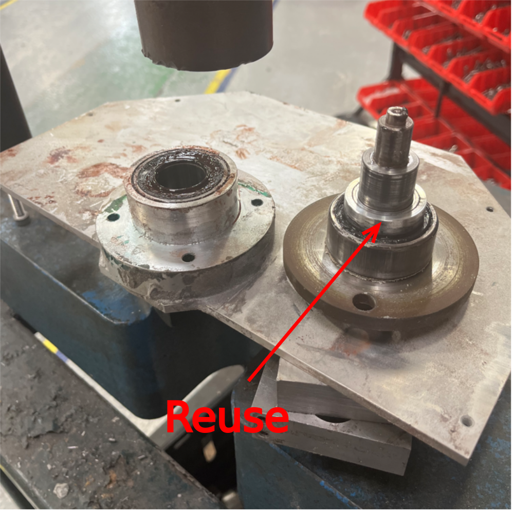
Étape 19 - Use press to remove blade flange
Press blade flange out of bearing assembly
Spacer between 2 bearings should be reused

Étape 20 - Remove bearing from housing
Remove bearing using drift and dispose of bearing


Étape 21 - Remove bearing housing
Disconnect 4 off M6 countersunk bolts and separate bearing housing from face plate
Both parts to be reused


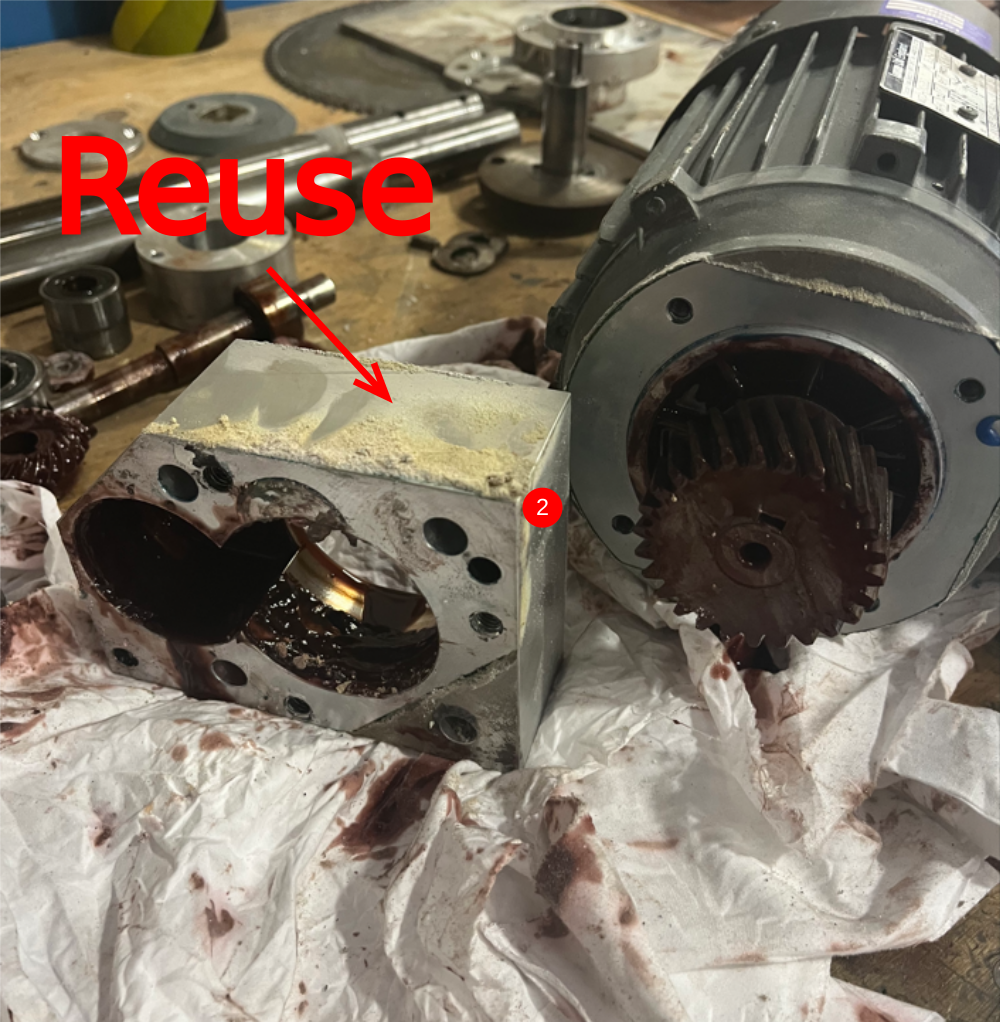
Étape 22 - Remove motor pinion housing
1 Remove 4 off M6 socket caps as shown
2 Separate block from motor
Motor pinion housing to be refurbished . Motor and pinion to be disposed
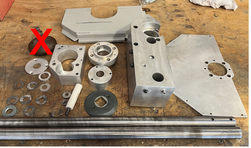
Étape 23 - Disposed parts not required


Étape 24 - Clean and degrease
Clean and degrease parts indicated for rebuild


Draft
 Français
 English
 Deutsch
 Español
 Italiano
 Português