Correct settings and installation procedure for transfer beam assemblies
Sommaire
- 1 Introduction
- 2 Étape 1 - Unless otherwise stated
- 3 Étape 2 - Install Frame pitching jigs
- 4 Étape 3 - Attach Jigs
- 5 Étape 4 - Move Module E
- 6 Étape 5 - Level module E
- 7 Étape 6 - Adjust height of module E
- 8 Étape 7 - Remove setting jigs
- 9 Étape 8 - Fit Transfer beam 1 and 9
- 10 Étape 9 - Information
- 11 Étape 10 - Check Parallel
- 12 Étape 11 - Check Squareness
- 13 Étape 12 - Adjust squareness
- 14 Étape 13 - Check adjustment
- 15 Étape 14 - Install Transfer beam 2
- 16 Étape 15 - Install Transfer beam 3
- 17 Étape 16 - Install Transfer beam 4
- 18 Étape 17 - Install Transfer beam 5
- 19 Étape 18 - Install Transfer beam 6
- 20 Étape 19 - Install Transfer beam 7
- 21 Étape 20 - Install Transfer beam 8
- 22 Étape 21 - Check Flatness
- 23 Commentaires
Introduction
Tools Required
Standard hex key set
Module pitching jigs
Tape measure 7.5 meter
Engineers level
1 meter spirit level
Parts required
Étape 1 - Unless otherwise stated
Use Loctite 243 on all fasteners
Use Loctite 572 on all threaded pneumatic connection
Pen mark all fasteners to show finalised
Étape 2 - Install Frame pitching jigs
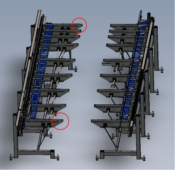
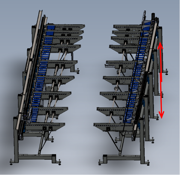
Module E will require accurately positioning to align with Module C
Only frame E must be moved
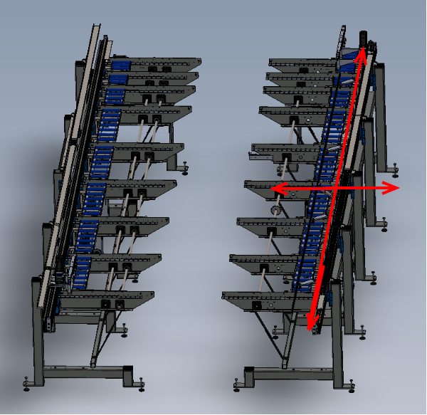
Étape 4 - Move Module E
Move module E in the directions shown to align to jigs
Fasten jigs to module E once aligned
Étape 5 - Level module E
Module E will require re levelling now it has been moved
Level from carriage plate for X axis and support arms for Y axis
Étape 6 - Adjust height of module E
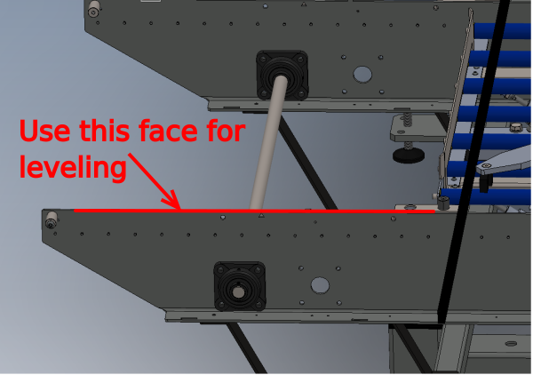
Using loading arms as datum , lift or lower Module E on adjusting bolts to bring module level with module C
Only use the face indicated for levelling between models. This is the face that is used in set up of the arms so continuity occurs for installation
Étape 8 - Fit Transfer beam 1 and 9
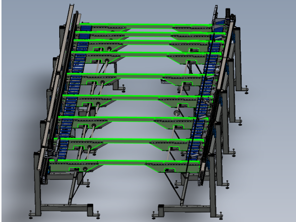
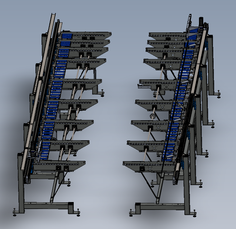
Fit transfer beam 1 (with pneumatic rail ) and transfer beam 9 (no pneumatic rail ) to modules
Fasten with button heads
Fasten with M8 x 20 set bolts
Do not use adhesive on these bolts as need to be removed for decommission
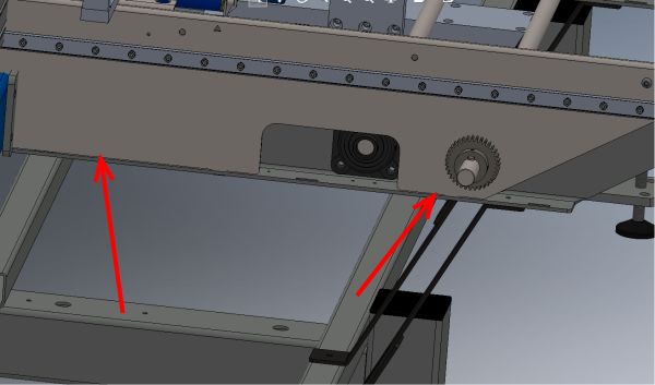
Check that transfer beams sit flat along indicated faces
Étape 9 - Information
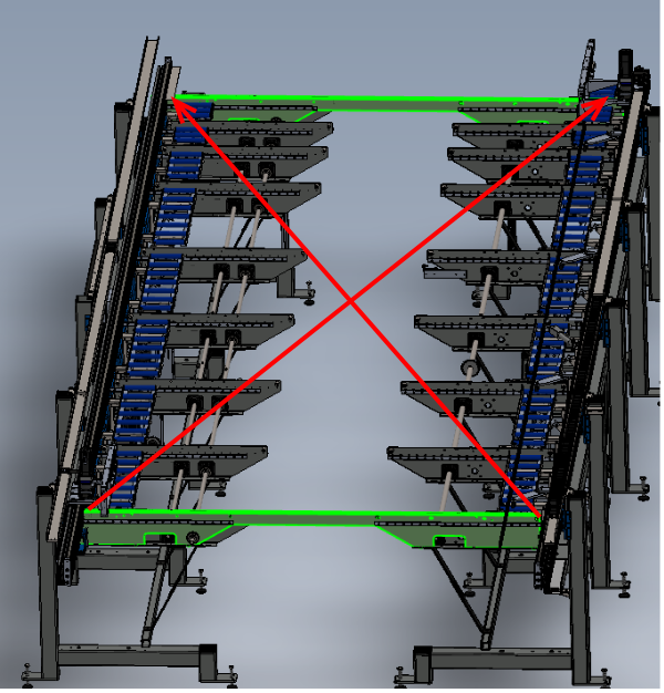
It is important that the squareness and parallel are checked after the levelling of the 2 frames in relation to each other.
If there is a large variance in height between the 2 modules, a discrepancy will be created when measuring for correct positioning
The amount of frame movement required after levelling has been performed will be minimal , and have negligible effect on levels set
Étape 10 - Check Parallel
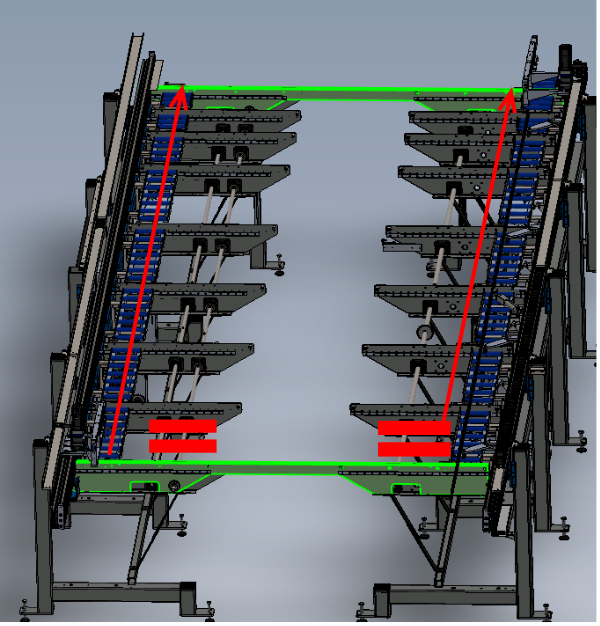
Check that beams are Parallel by measuring with a tape measure
Report any discrepancy to supervisor
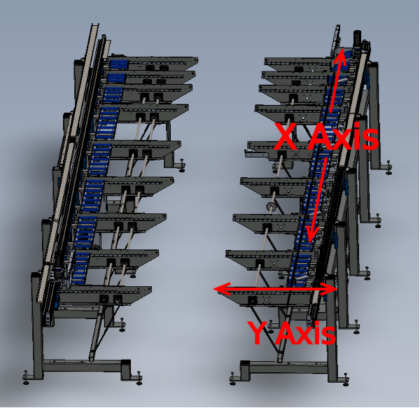
Étape 12 - Adjust squareness
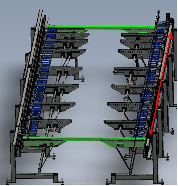
Adjust Squareness by moving Module E in the direction shown
Frame will need to move half the distance of the discrepancy measured on corner measurements
Étape 13 - Check adjustment
Once adjustment is complete, check measurements and levels of all areas adjusted
Étape 14 - Install Transfer beam 2
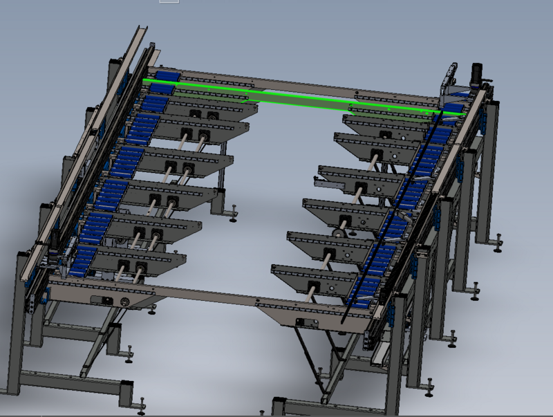
Install transfer beam 2 and secure
Fasten with M8 x 20 set bolts
Do not use adhesive on these bolts as need to be removed for decommission
Étape 15 - Install Transfer beam 3
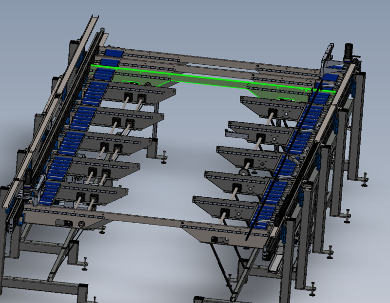
Install transfer beam 3 and secure
Fasten with M8 x 20 set bolts
Do not use adhesive on these bolts as need to be removed for decommission
Étape 16 - Install Transfer beam 4
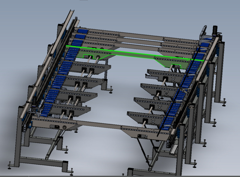
Install transfer beam 4 and secure
Fasten with M8 x 20 set bolts
Do not use adhesive on these bolts as need to be removed for decommission
Étape 17 - Install Transfer beam 5
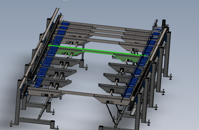
Install transfer beam 5 and secure
Fasten with M8 x 20 set bolts
Do not use adhesive on these bolts as need to be removed for decommission
Étape 18 - Install Transfer beam 6
Install transfer beam 6 and secure
Fasten with M8 x 20 set bolts
Do not use adhesive on these bolts as need to be removed for decommission
Étape 19 - Install Transfer beam 7
Install transfer beam 7 and secure
Fasten with M8 x 20 set bolts
Do not use adhesive on these bolts as need to be removed for decommission
Étape 20 - Install Transfer beam 8
Install transfer beam 8 and secure
Fasten with M8 x 20 set bolts
Do not use adhesive on these bolts as need to be removed for decommission
Étape 21 - Check Flatness
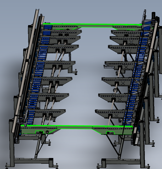
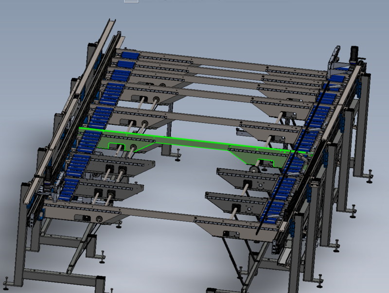
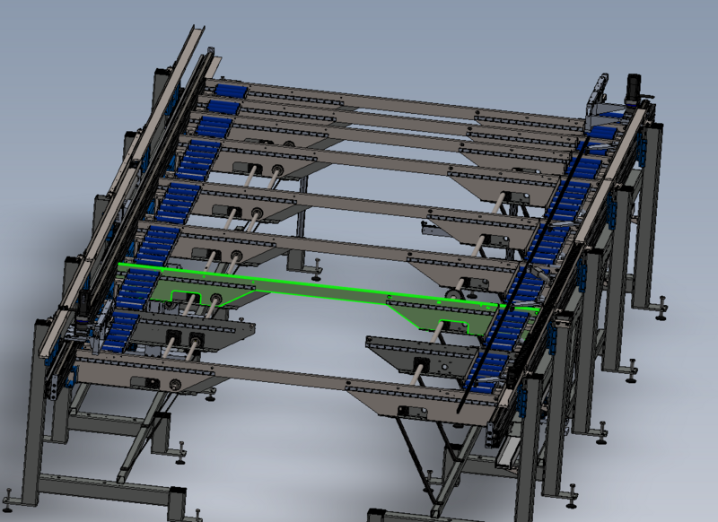
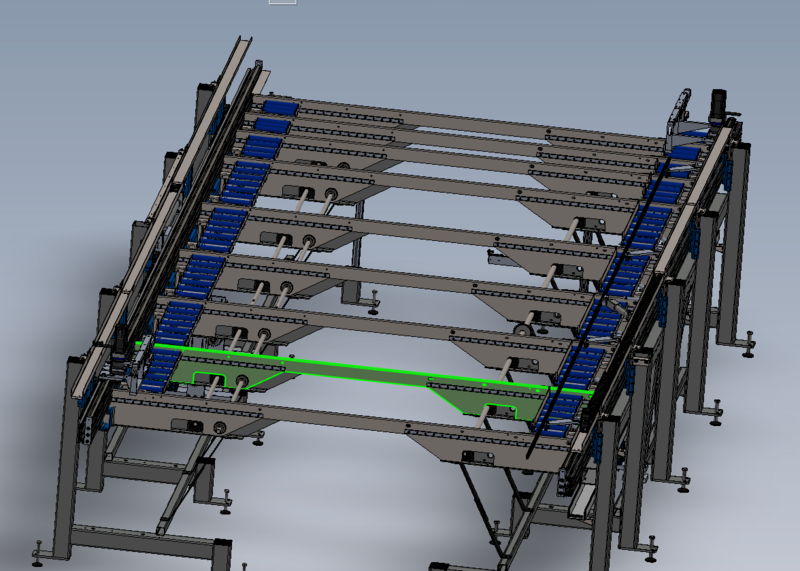
Once all transfer beams are installed, check flatness with a 2 meter straight edge
Span across arms with 2 meter straight edge and check that no arms are sitting higher or lower than other transfer arms
Sign off required by supervisor
Draft




 Français
 English
 Deutsch
 Español
 Italiano
 Português