Correct installation , setting and quality checks for installation of material sensor beam


Difficulté
Difficile
Durée
1 heure(s)
Sommaire
- 1 Introduction
- 2 Étape 1 - Unless otherwise stated
- 3 Étape 2 - Attach mounting brackets to module C and E
- 4 Étape 3 - Position and fix Assembled beam
- 5 Étape 4 - Set height of assembled beam
- 6 Étape 5 - Setting Height
- 7 Étape 6 - Repeat at point B
- 8 Étape 7 - Finalise fasteners
- 9 Étape 8 - Set sensor positions
- 10 Commentaires
Introduction
Tools Required
Standard hex key set
2 Meter straight edge
Parts Required
R0015060 Bench Assemble Flapper Beam
Étape 1 - Unless otherwise stated
Use Loctite 243 on all fasteners
Use Loctite 572 on all threaded pneumatic connection
Pen mark all fasteners to show finalised

Étape 2 - Attach mounting brackets to module C and E
Attach mounting brackets as shown


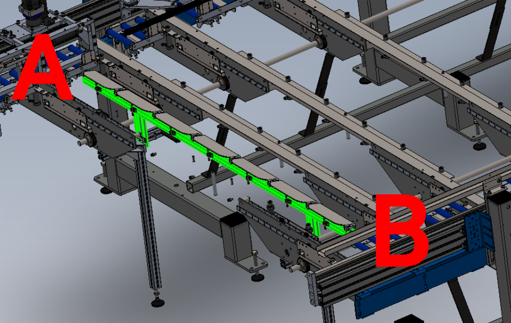
Étape 3 - Position and fix Assembled beam
(front transfer beam removed for clarity )
Fix assembled beam to supports as shown
Do not finalise fasteners

Étape 4 - Set height of assembled beam
Use sliding adjustment on maytec angles /frame to adjust height of assembly
To determine correct height Set end A and B separately
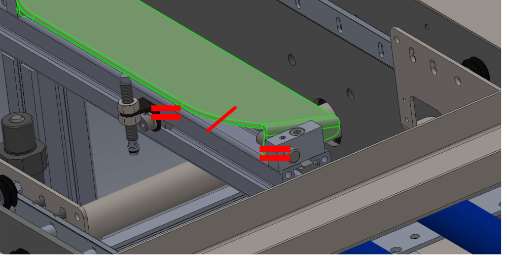
Étape 5 - Setting Height
Span over transfer beams 1 and 2 with straight edge at point A
Lift or lower sensor rail assembly to match the following criteria
When straight edge is pushed to meet radius of sensor plate, it must strike at indicated point of halfway around radius on paddle
Étape 6 - Repeat at point B
Repeat height setting at point B using same criteria
Once point B is set, check that point A has not altered

Étape 7 - Finalise fasteners
Once correct settings have been achieved, double check and finalise all fasteners used for adjusting and mounting .
Ensure all fasteners have 243 applied to threads and are pen marked as complete
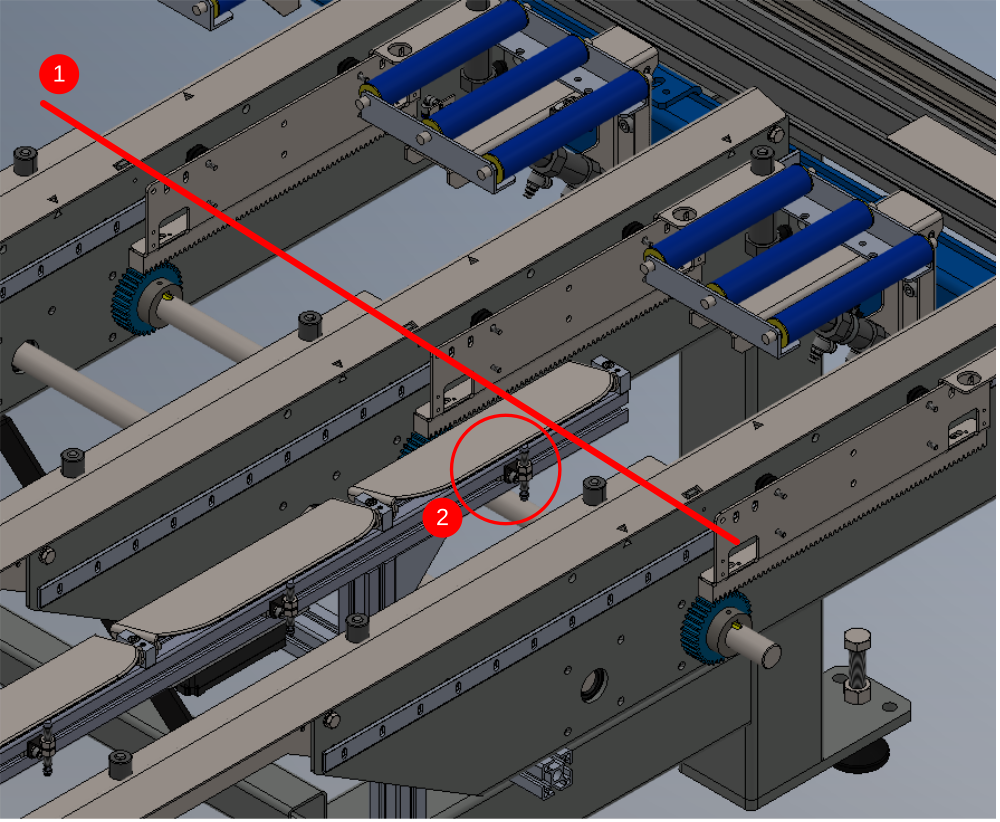
Étape 8 - Set sensor positions
Repeat for each individual Sensor and paddle
1 Place straight edge over transfer beams and above sensor paddle to be set
2 Adjust sensor to touch paddle in this position
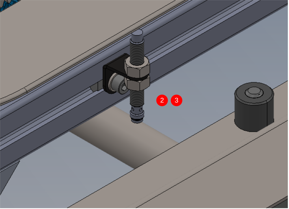
3 Wind sensor back 1/2 turn
4 tighten lock nuts to finalise, checking that shakeproof washers have been fitted to sensor

Draft
 Français
 English
 Deutsch
 Español
 Italiano
 Português