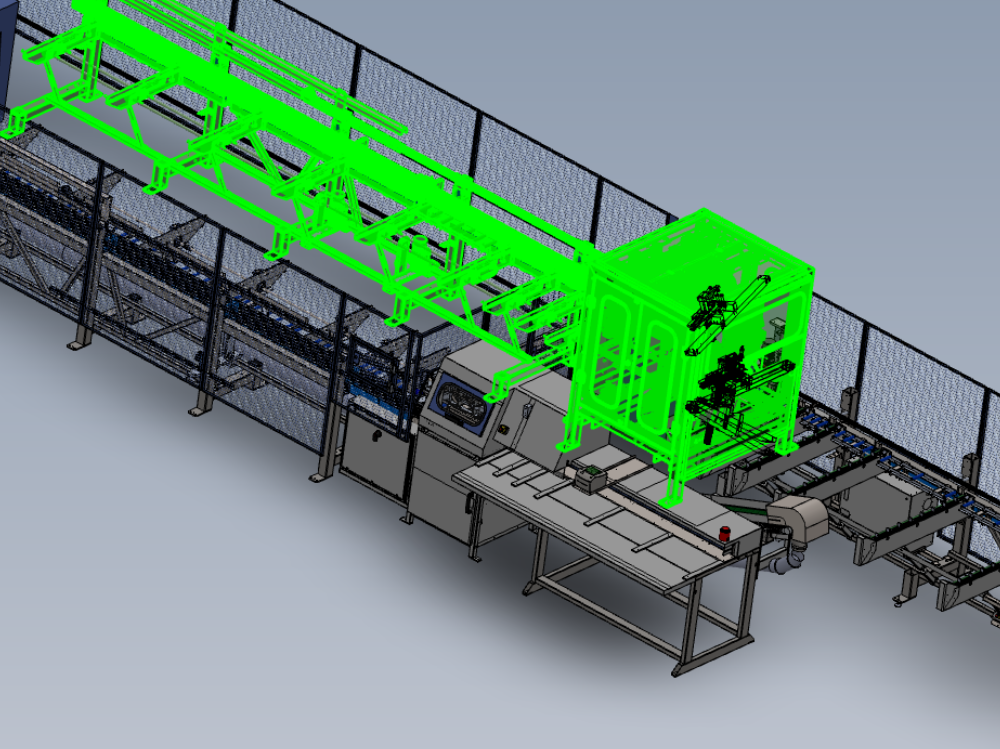
Alignment process and criteria for module B to C

Difficulté
Difficile
Durée
2 heure(s)
Sommaire
- 1 Introduction
- 2 Étape 1 - Quality check
- 3 Étape 2 - Position Module B
- 4 Étape 3 - Quality check
- 5 Étape 4 - Level module B
- 6 Étape 5 - Finalise X axis position
- 7 Étape 6 - Set Gripper pin position A
- 8 Étape 7 - Set Gripper pin position B
- 9 Étape 8 - Repeat Steps 6 and 7
- 10 Étape 9 - Set Module B height
- 11 Étape 10 - Recheck settings
- 12 Étape 11 - Check gripper clearance
- 13 Étape 12 - Laser alignment Height
- 14 Étape 13 - Laser alignment Parallel
- 15 Étape 14 - Move Gripper
- 16 Étape 15 - Cast laser to Gripper
- 17 Étape 16 - Connect Ring mains
- 18 Commentaires
Introduction
Alignment details and level settings for correct alignment of module B to module C
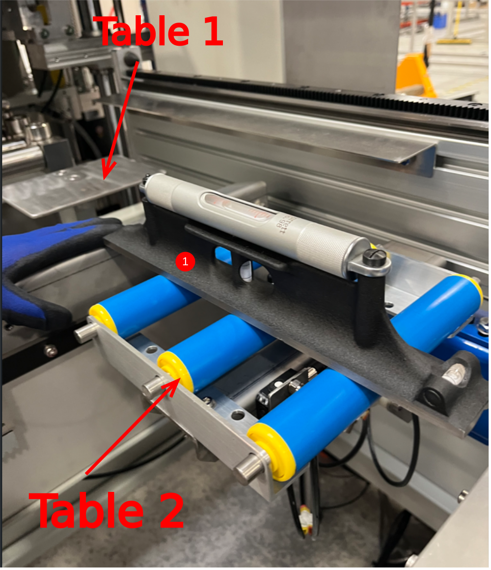
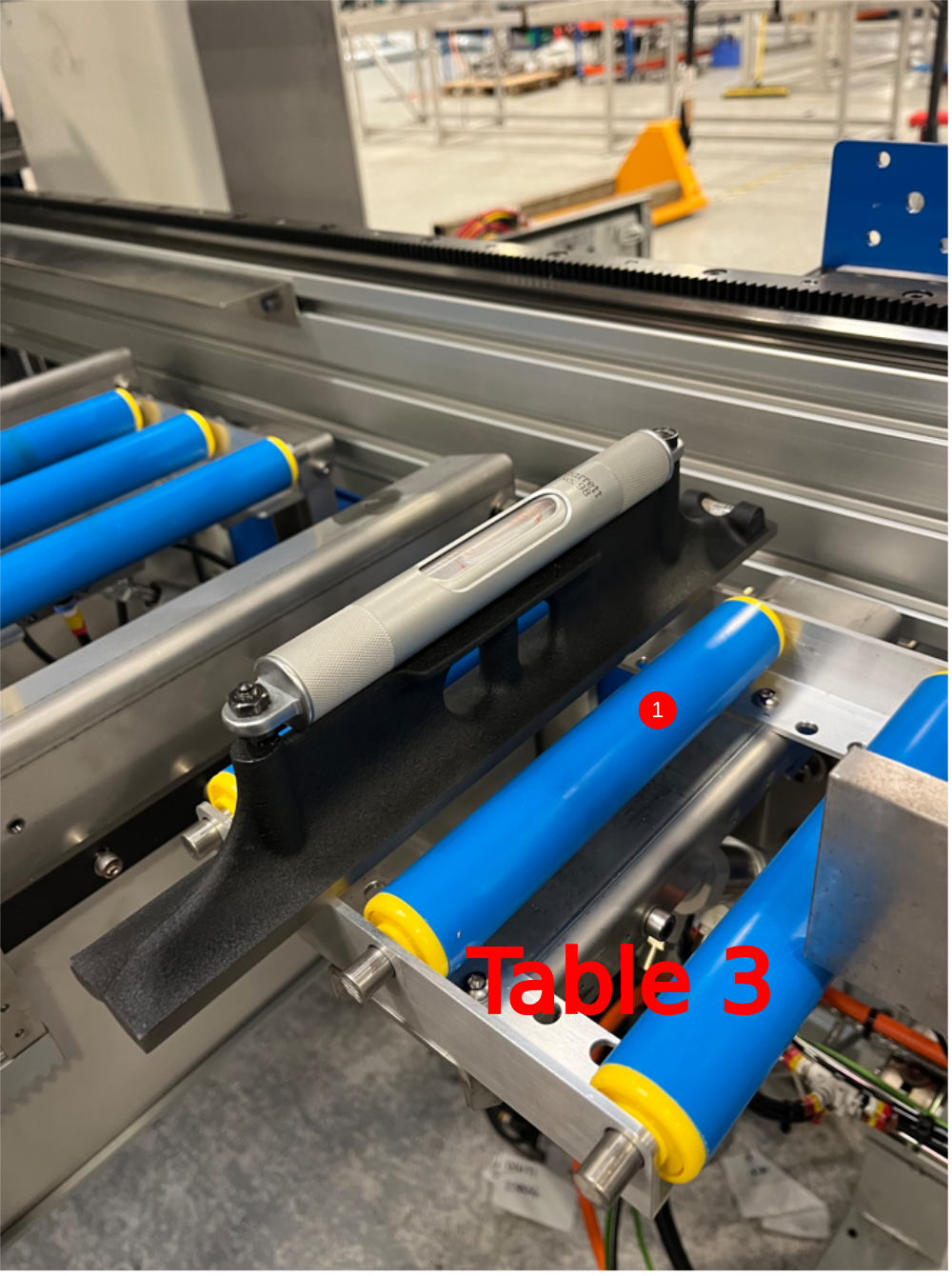
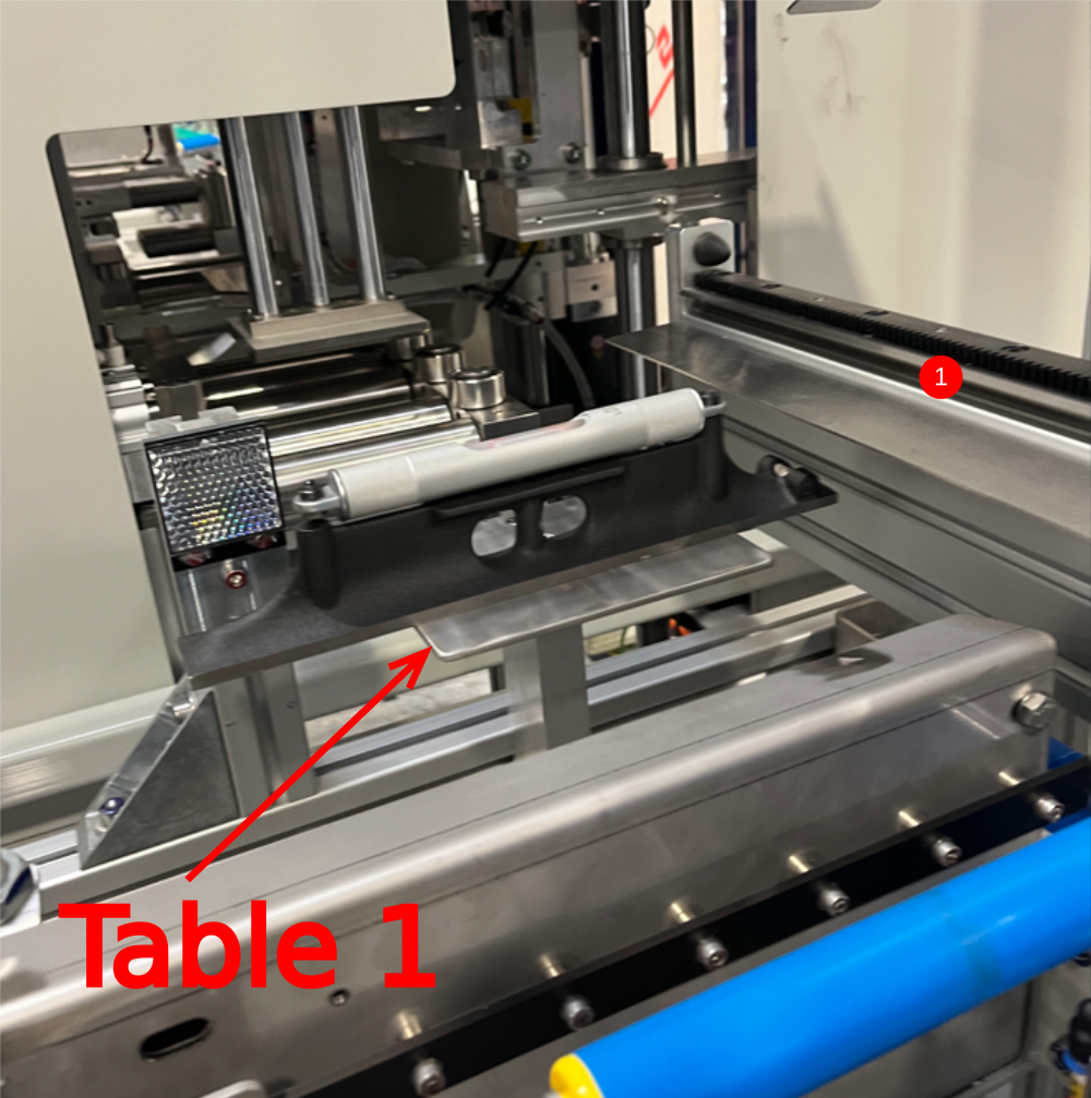
Étape 1 - Quality check
Before installing module B, module C roller tables should be double checked for correct positioning
1 To do this inspect tables 1, 2,3 and 4 for level as shown.
2 Also inspect alignment with 2 meter straight edge. All rollers should be on the same height and no bump up should be present when moving the straight edge over the table.
3 Ensure fixed table is at same height as rollers
Report any discrepancies to supervisor for correct remedial action
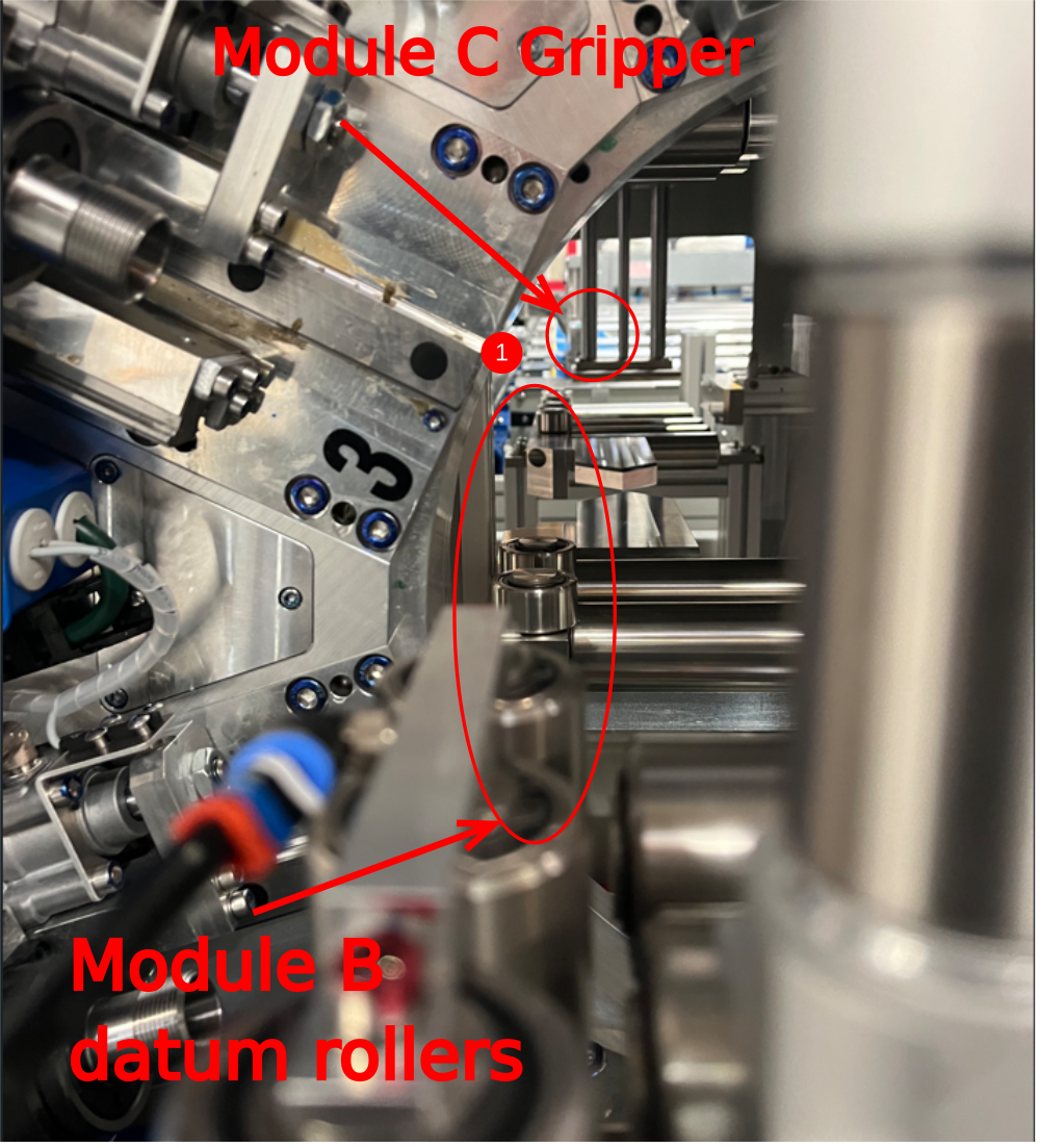
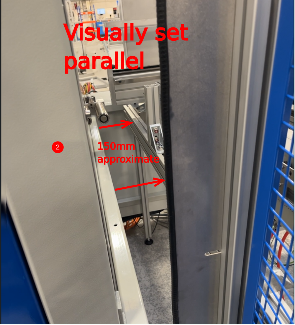
Étape 2 - Position Module B
Position module B into approximate position and use reference points as listed
1 Set Y axis position using Module C gripper and Module B backfences as reference. Visually set approximately gripper just in front of datum rollers
2 Set X axis position by using back of module B and transfer buffer bar as reference. Set bars shown visually parallel and approximately 150mm apart
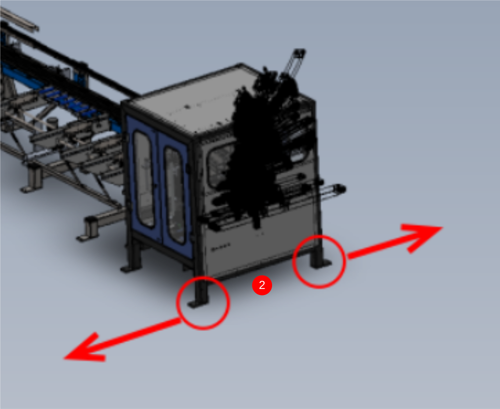
3 Ensure all 4 adjustment feet and set in levelling pads and touching
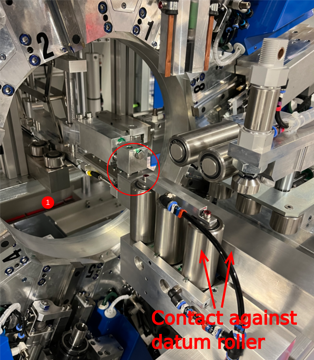
Étape 3 - Quality check
Before installation a quality check should be performed on Module ?b datum rollers
Check horizontal and vertical rollers
Use 2 meter straight edge to check alignment of rollers as shown . Tolerance 0.002" /0.05mm . Any discrepancy should be reported to supervisor for suggested remedial action


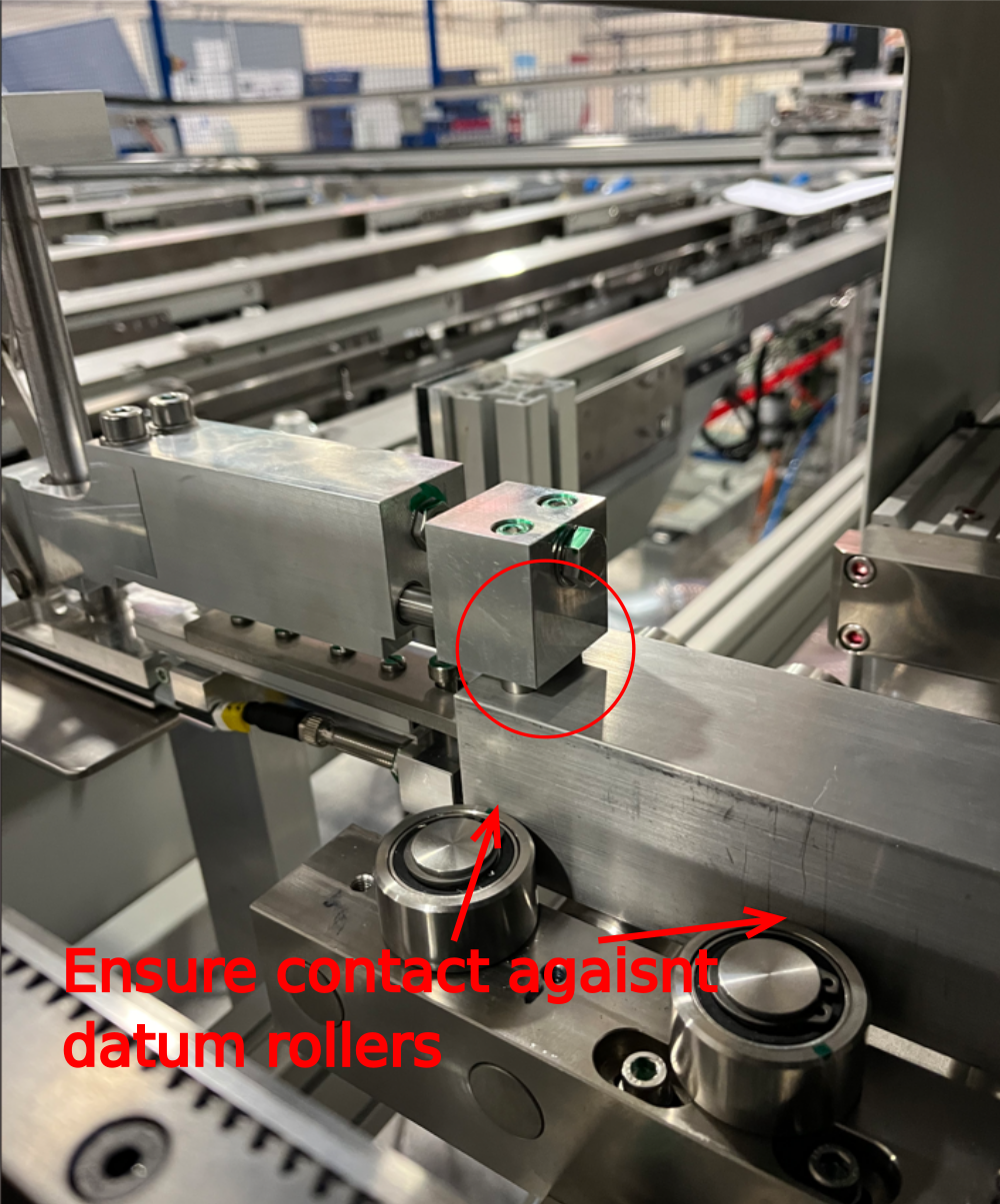
Étape 4 - Level module B
1 Level Y axis using indicated point
2 Level X axis as shown using 2 meter straight edge on horizontal rollers
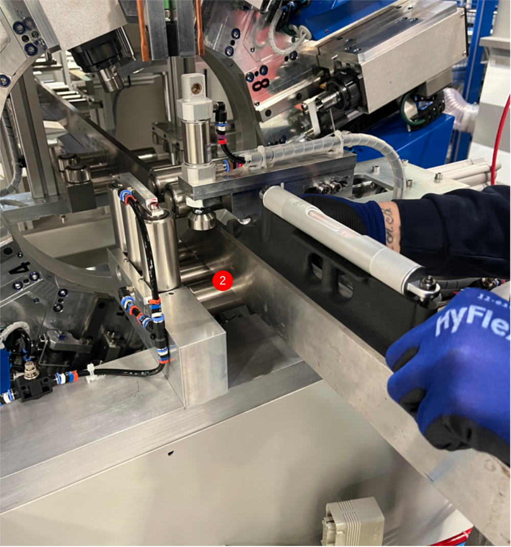
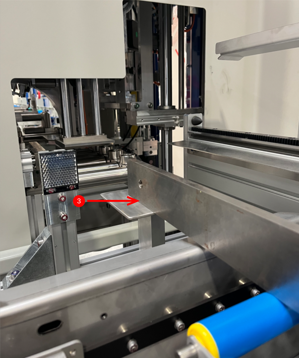
Étape 5 - Finalise X axis position
1 Move Module C hepco beam to its fully extended position into Module B
2 Adjust position of module B to set gap as shown at 75mm
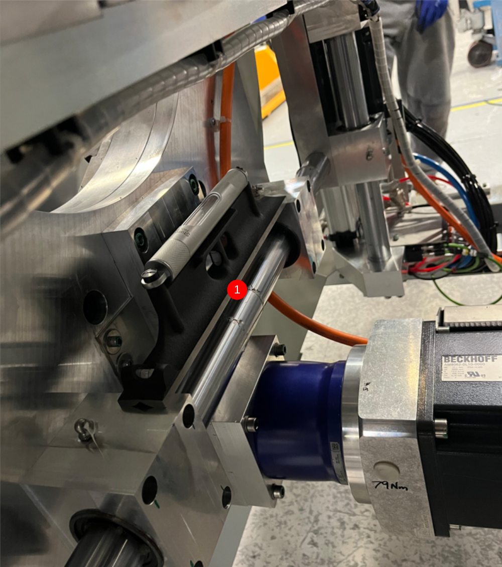
Étape 6 - Set Gripper pin position A
1 With Hepco beam fully extend, move gripper to position shown
2 Insert grip pin jig as shown, and adjust Module B position to set gripper pins to enter jig perfectly
Étape 7 - Set Gripper pin position B
1 Move gripper to position shown
2 Insert grip pin jig as shown, and adjust Module B position to set gripper pins to enter jig perfectly

Étape 8 - Repeat Steps 6 and 7
Move gripper to position A and recheck pin jig setting. Adjust if required to correct. If any adjustments are required, it is vital that the other point is checked after.
Continue to adjust and correct until no adjustments are needed and both pin jig positions are correct
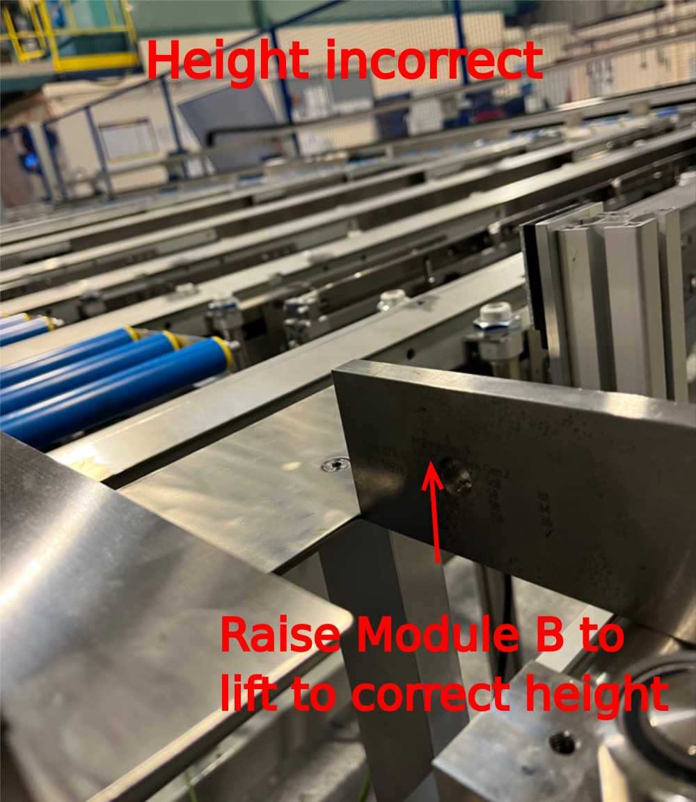
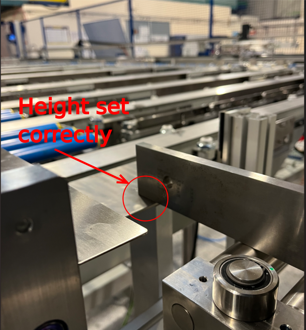
Étape 9 - Set Module B height
Use 2 meter straight edge in Module b as shown to extend height out to Module C fixed table
Adjust height of module B to set datum roller heights to be 0.25-0.5mm above fixed cut table on Module C
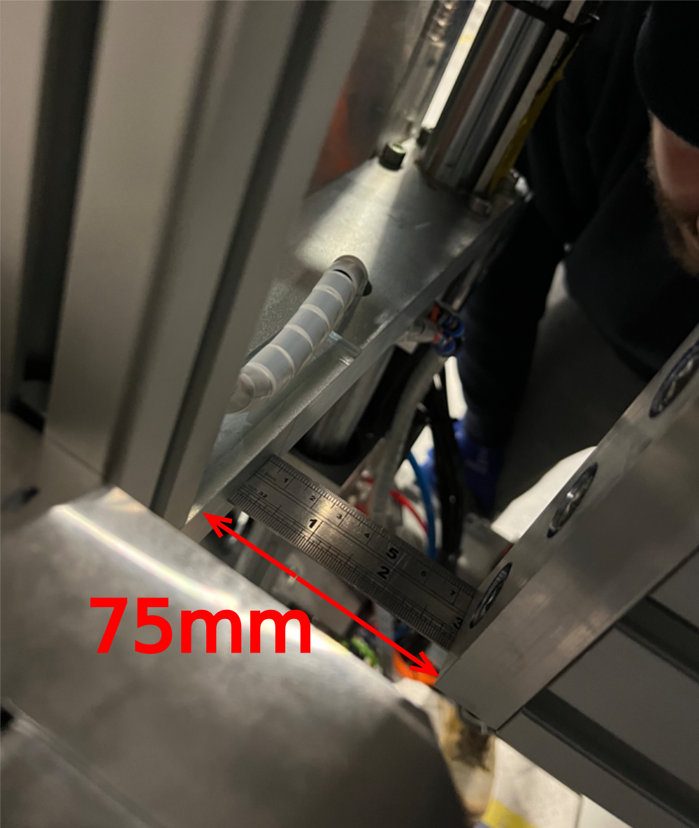
Étape 10 - Recheck settings
Once pin alignment has been set, it is vital all previous settings are checked to ensure they have not been affected
1 Check Y and X axis levels
2 Check correct gap is still present between Hepco beam and module B
75mm -+3mm Tolerance
If any adjustments are require, please ensure height between module B and C is rechecked after adjustments are made

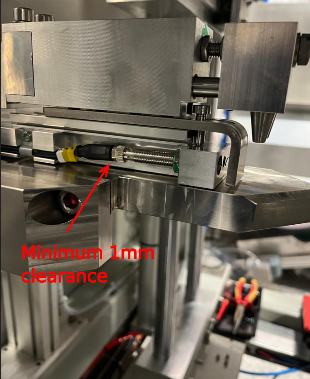
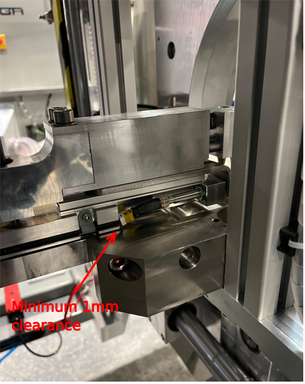
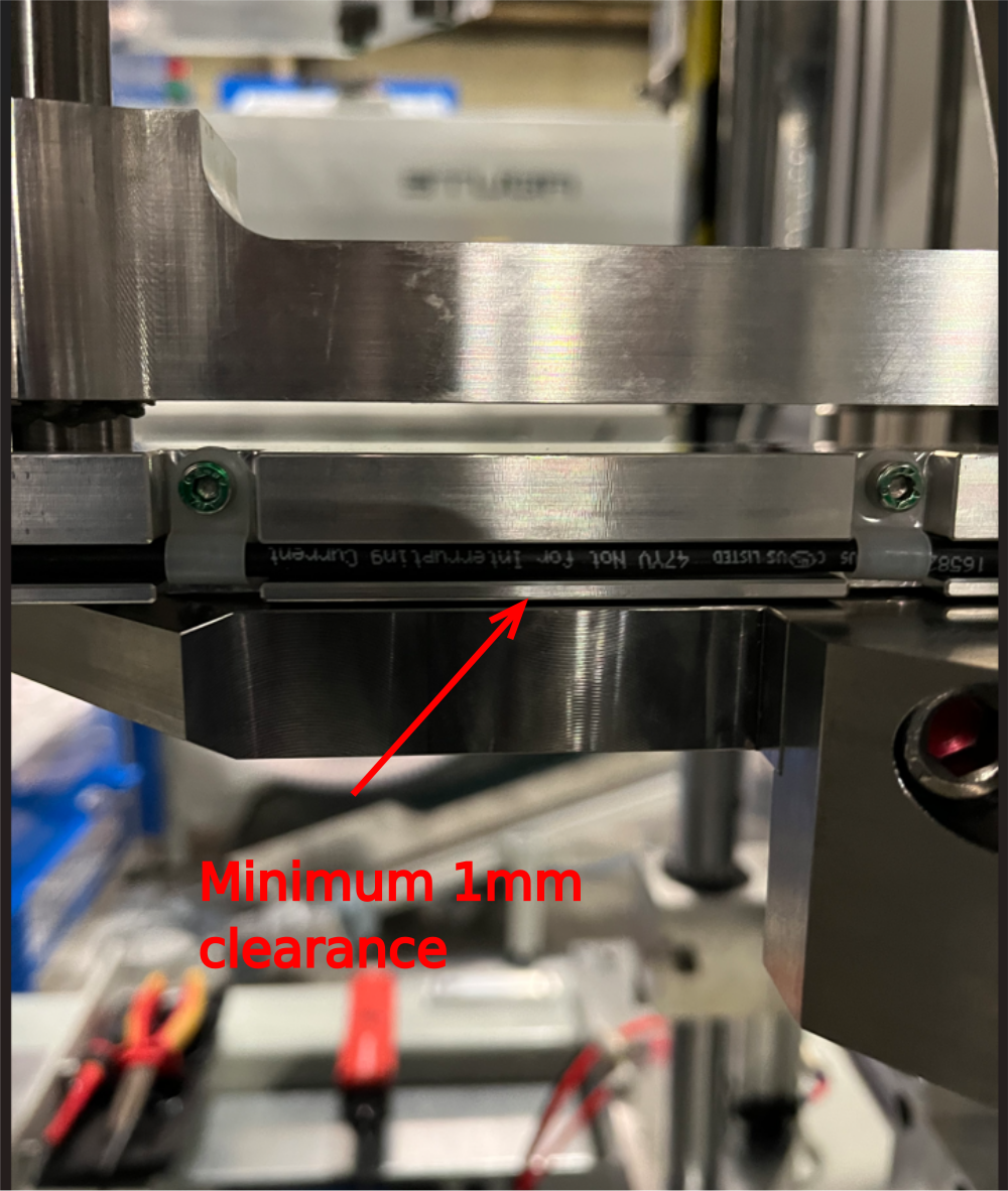
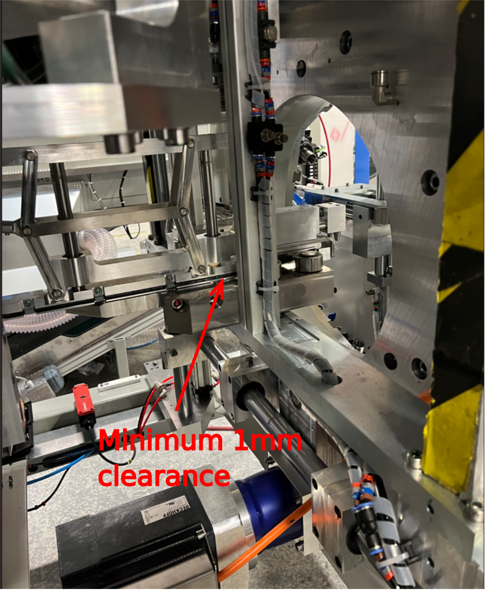
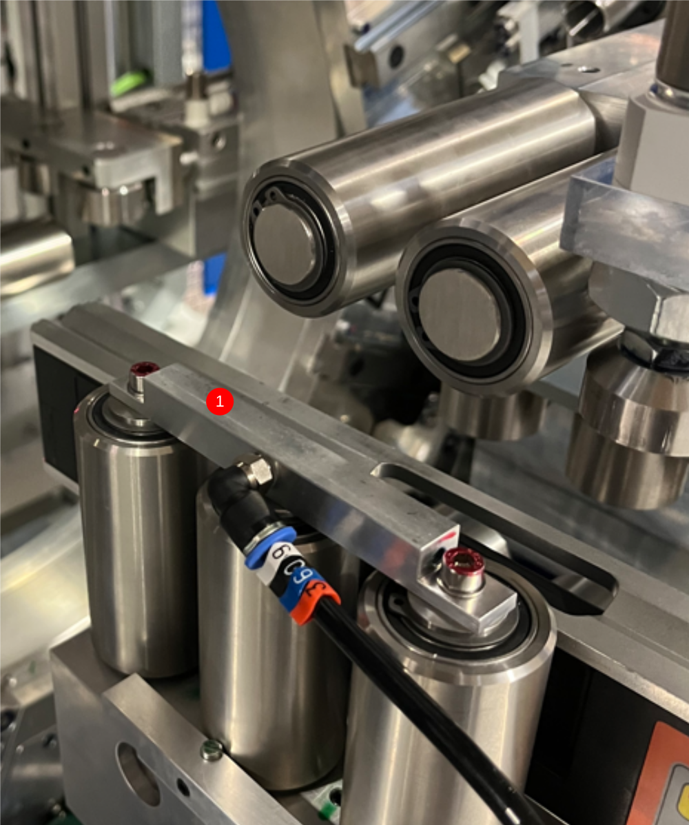
Étape 11 - Check gripper clearance
Check gripper clearance above Module B datum rollers and cut tables
Move gripper into machining centre . Ensure hepco beam is fully extended
Check clearance is present minimum 1mm gripper above rollers
Check in all positions through module B
Report any collisions to supervisor
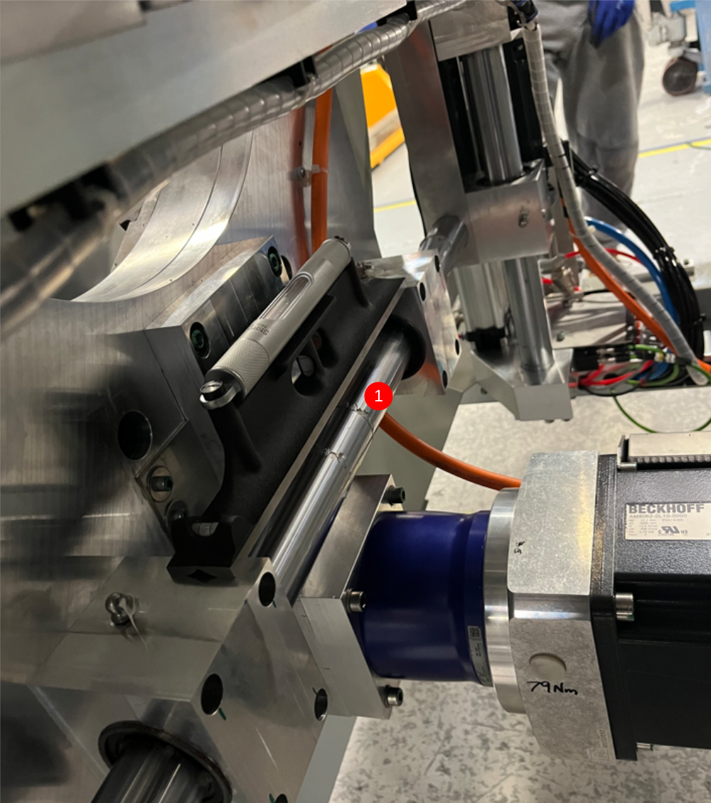
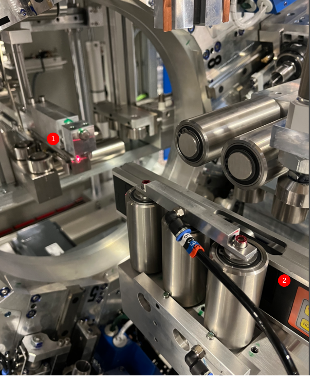
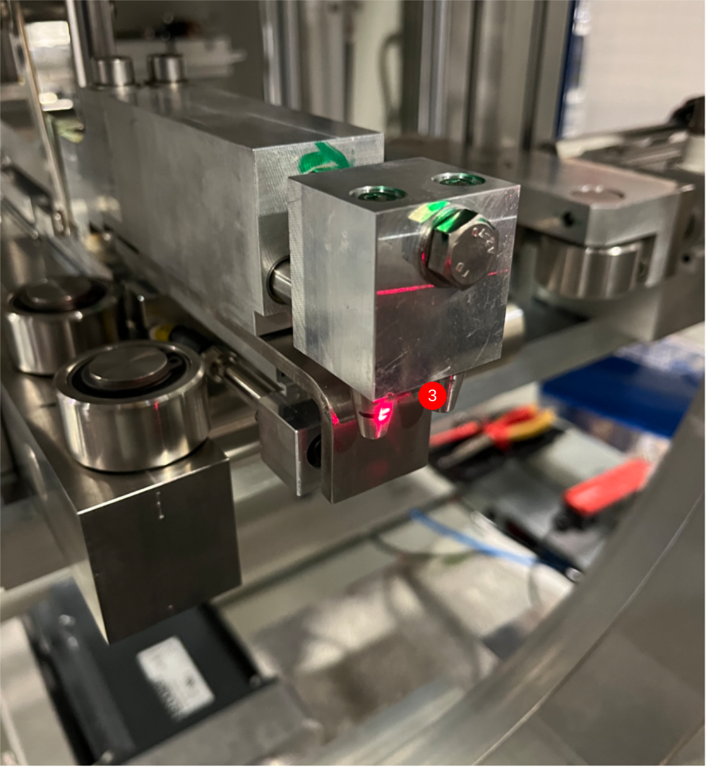
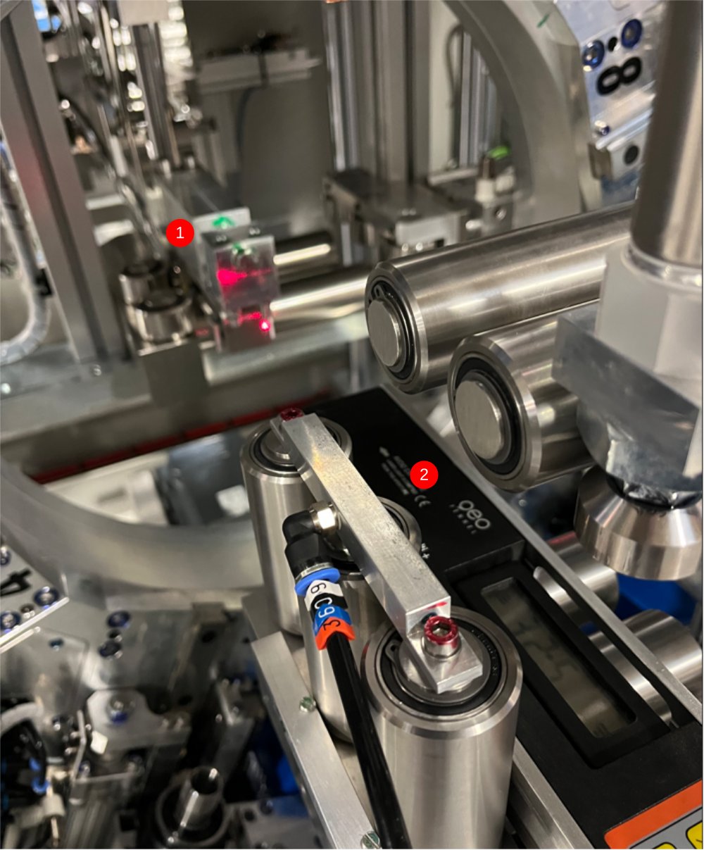
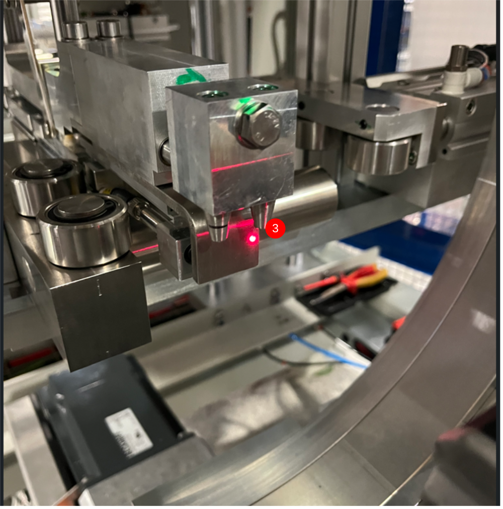
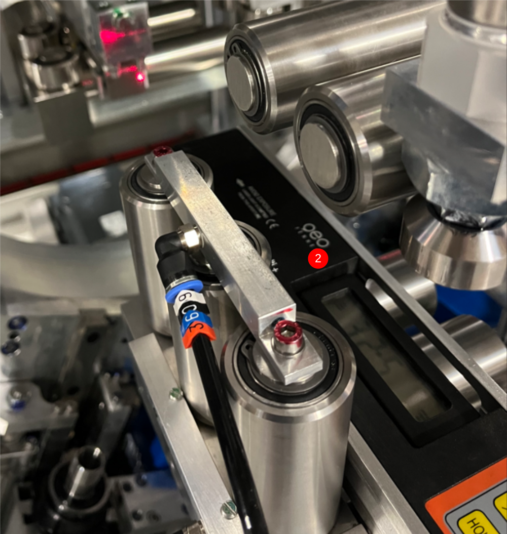
Étape 12 - Laser alignment Height
1 Move gripper to point just in front of clamps as shown
2 Position laser as shown on horizontal datum rollers
3 Project laser onto gripper and mark horizontal line as shown to match laser
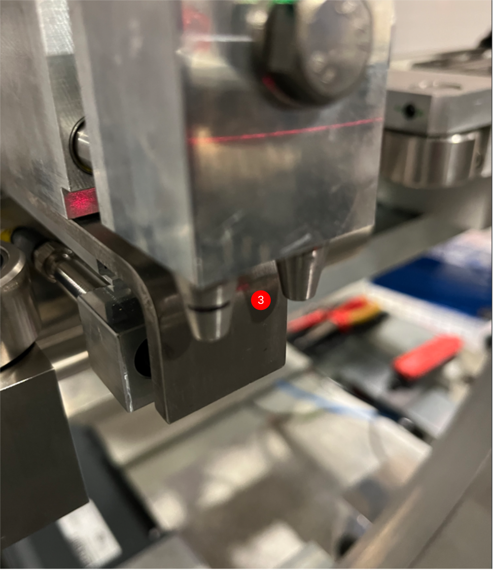
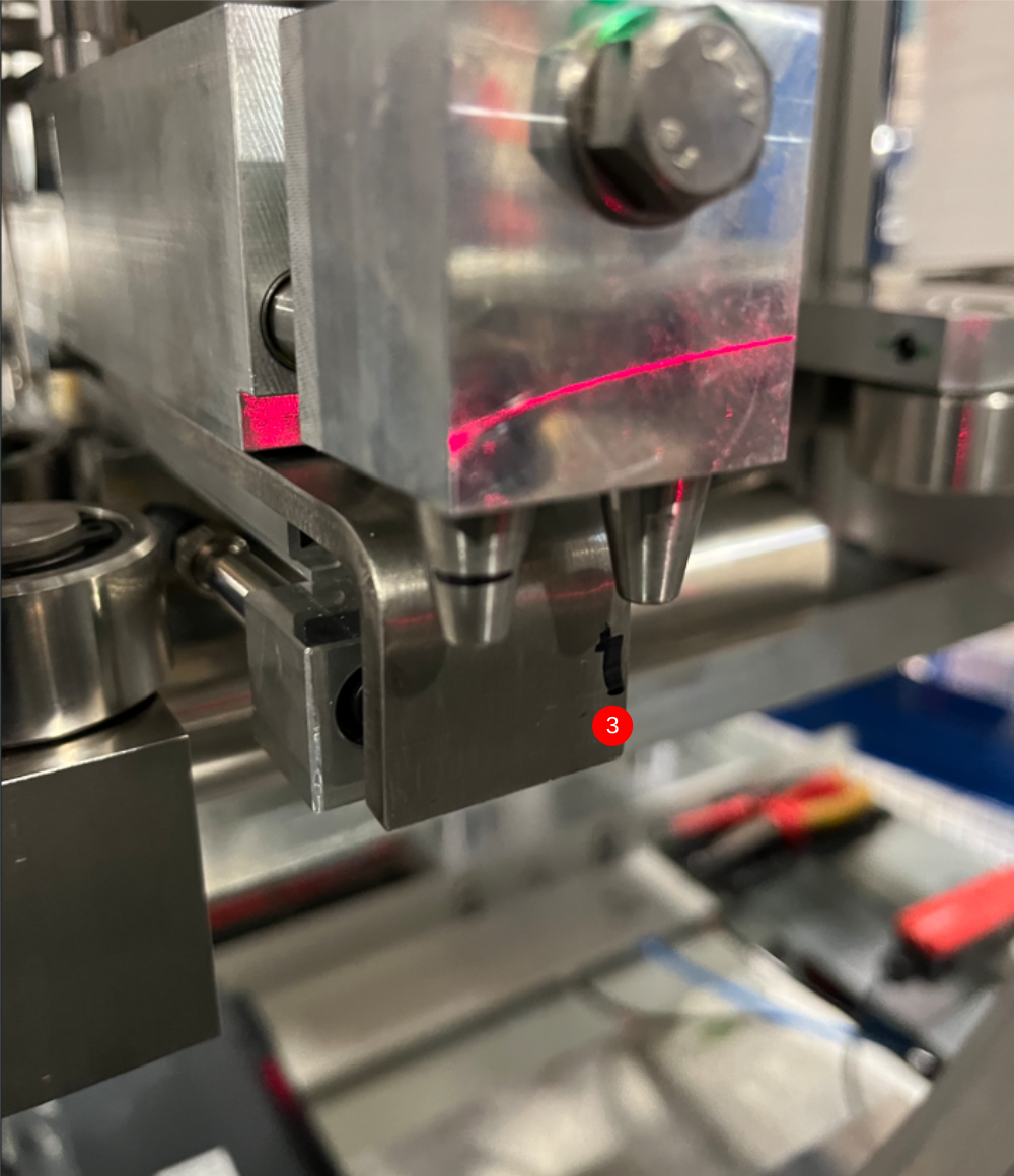
Étape 13 - Laser alignment Parallel
1 Move gripper to point just in front of clamps as shown
2 Position laser as shown on vertical datum rollers
3 Project laser onto gripper and mark vertical line as shown to match laser
Étape 14 - Move Gripper
Move gripper to furthest point away from Module B
Ensure hepco beam is also fully retracted from module B


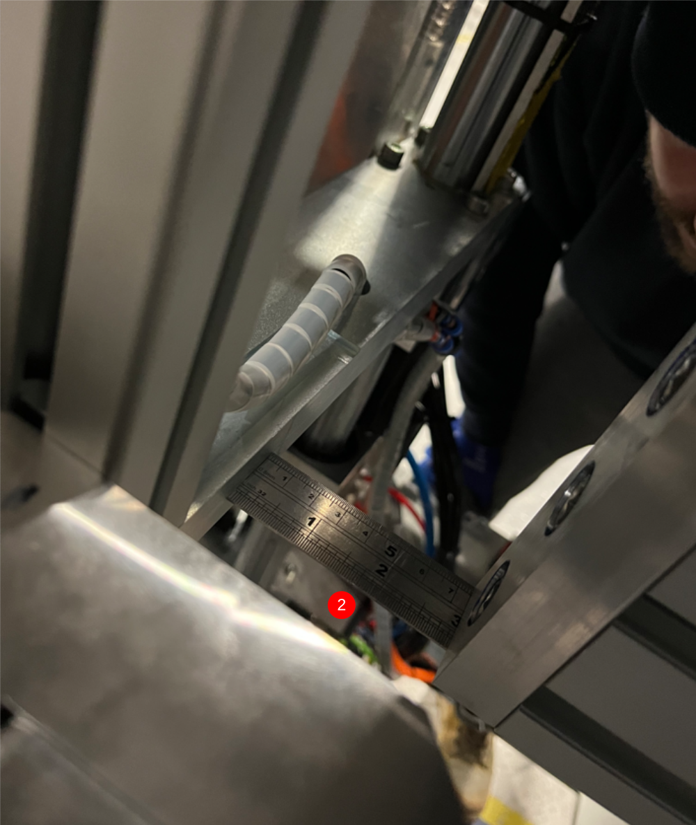
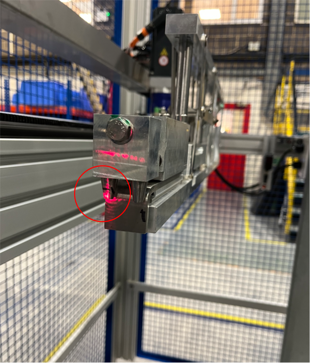
Étape 15 - Cast laser to Gripper
Height
1 With laser in position shown, project to gripper at far end of frame. Working on the horizontal line, inspect to achieve difference. Tolerance -+5mm . Any discrepancy greater than 5mm should be reported to supervisor
Parallel
2 With laser in position shown, project to gripper at far end of frame. Working on the Vertical line, inspect to achieve difference. Tolerance -+2mm .
Module B can be adjusted to correct this measurement
Move points as shown to correct laser reading
Étape 16 - Connect Ring mains
Connect 2 off 12mm red pipes from transfer wire basket to bulkheads at rear of module B. Leave pipes long to allow final trimming on installation
Connect 1 off 12mm blue airpipe from module C into bulkheads at rear of module B. Leave pipe long to allow final trimming on installation

Draft
 Français
 English
 Deutsch
 Español
 Italiano
 Português