Key Steps for mechanical installation of ZX5

Difficulté
Très difficile
Durée
4 jour(s)
Sommaire
- 1 Introduction
- 2 Étape 1 - Information links
- 3 Étape 2 - Module Positioning
- 4 Étape 3 - Module order of positioning and levelling
- 5 Étape 4 - Identify correct factory location and set position
- 6 Étape 5 - Support post installation
- 7 Étape 6 - Levelling of multi outfeed or saw infeed Y axis
- 8 Étape 7 - Check reference points
- 9 Étape 8 - Levelling of multi outfeed or saw infeed X axis
- 10 Étape 9 - Position 2nd frame Saw infeed or Multi head outfeed
- 11 Étape 10 - Adjust height of 2nd levelled frame to match first
- 12 Étape 11 - Add 2 Transfer beams and Parallel set between hepco Rails
- 13 Étape 12 - Check and Set squareness of transfer table
- 14 Étape 13 - Add remaining transfer beams
- 15 Étape 14 - Check flatness of transfer beam top faces
- 16 Commentaires
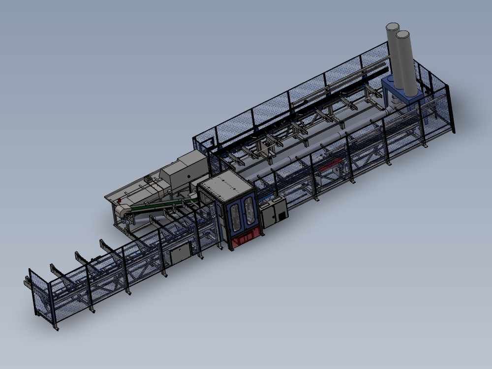
Introduction
Key data for installation of ZX5
Dokit to generate consistency of installation
Quality checks for installation
Étape 1 - Information links
In each step if applicable, Manufacturing links have been included to aid the installation progress for correct understanding of assembly process to achieve desired results
Please use the links if any adjustments have to be made on site, as critical measurements and setting details will be provided within the build data
Please ensure any quality/ discrepancies are correctly reported if encountered

Étape 2 - Module Positioning
Identify if either saw infeed or multi head outfeed is the logical frame to place first .
Consider access to machine when installing 1st frame
Consider handing of machine

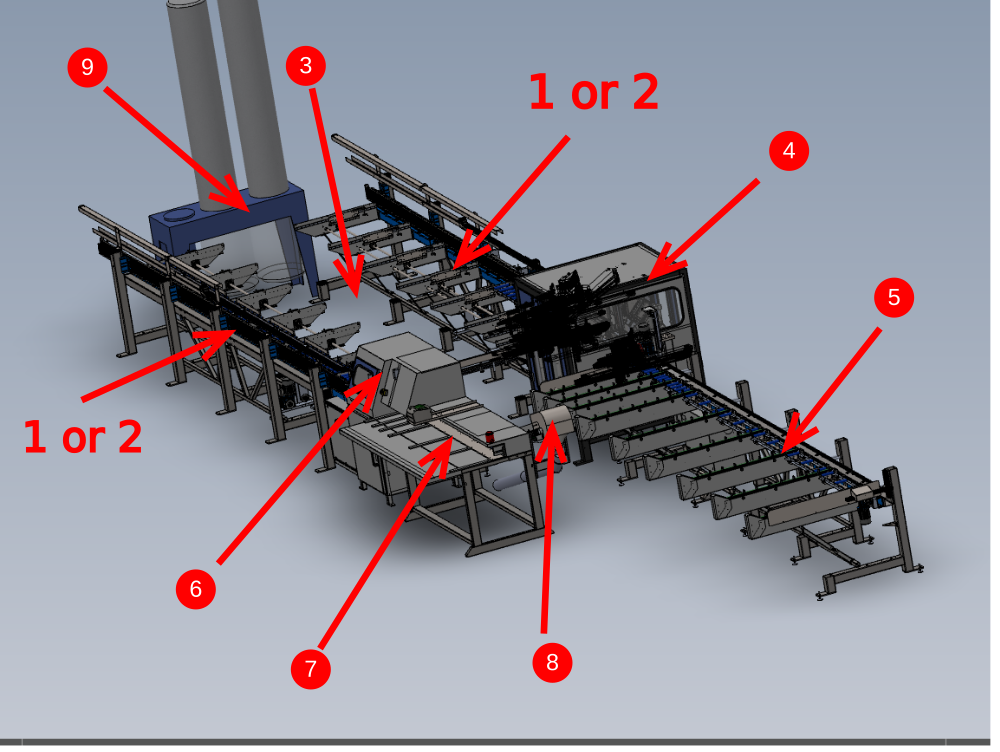
Étape 3 - Module order of positioning and levelling
- Saw infeed or Multi head outfeed
- multihead outfeed or saw infeed
- transfer table
- Machining centre
- Machining centre infeed
- Saw module
- Saw outfeed table
- Conveyor
- Extraction
- Guarding
Étape 4 - Identify correct factory location and set position
Position first frame identified to be first and set parallel to installation area
Take into consideration walkways, access one machine is installed and service connections

Étape 5 - Support post installation
It is vital the support arm is utilized at this point to allow correct adjustment of position 1 and 2 support arms
Use the adjustment in the foot to correctly level arms 1 and 2


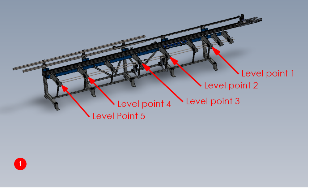
Étape 6 - Levelling of multi outfeed or saw infeed Y axis
Both frames will be initially levelled in the same way, and then fine tuned once multi head or saw is installed
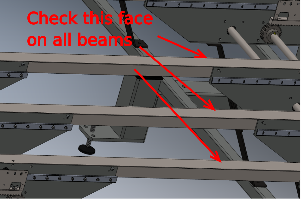
Y axis levelling
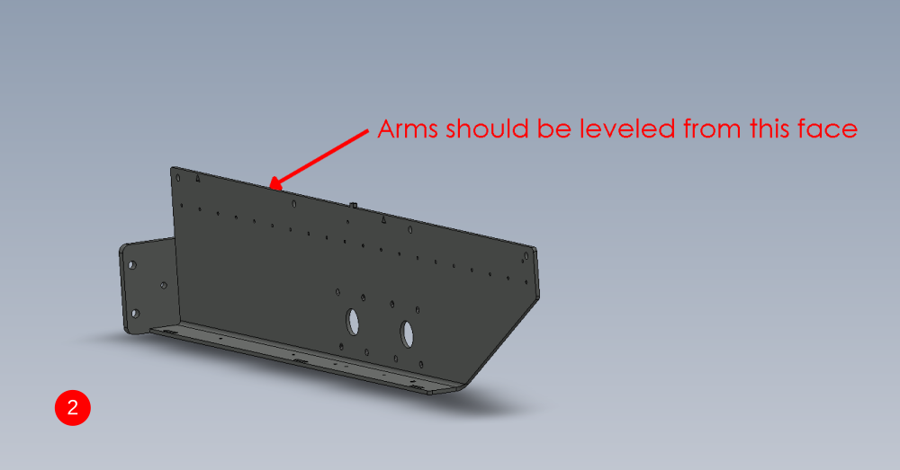
- Only level the arms at the positions indicated, as these are the only arms that sit directly above adjustment feet
- Level support arms from the indicated face

Étape 7 - Check reference points
Once the previous step has been performed, reference brackets should be checked to confirm factory setting has been achieved
The levelling brackets indicated should match the level of the support arms
Discrepancy should be immediately reported

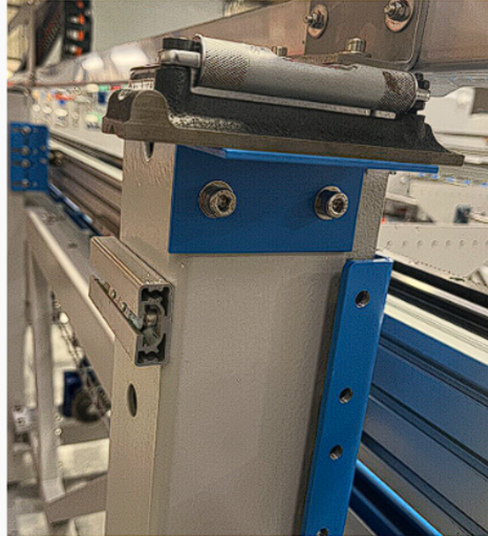
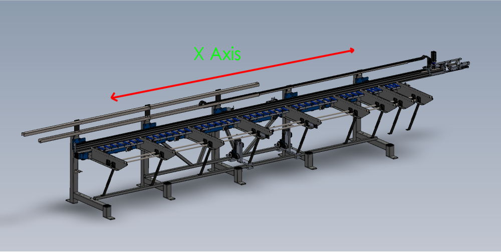
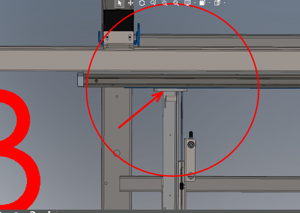
Étape 8 - Levelling of multi outfeed or saw infeed X axis
X axis is initially set up using the carriage plate as a register. Once additional units are installed and levelled , this x axis setting will be re checked and adjusted if required
Please note photo of level is taken from production stage. It is to give reference of the part to be used to to set X axis level. Position level at available point on assembled carriage plate
R0015028D ZX5 Hepco Beam Alignment Module C
R0015028D ZX5 Hepco Beam Alignment Module C part 2


Étape 9 - Position 2nd frame Saw infeed or Multi head outfeed
- Position second frame opposing first one which has been levelled
- Use measurement shown to set the frames roughly the correct distance apart
- Move the frame on the x axis to visually line up the support arms on both frame
- Level second frame using steps for levelling first frame above


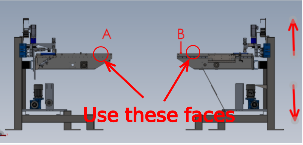
Étape 10 - Adjust height of 2nd levelled frame to match first
Points A and B should be level with each other.
Adjust 2nd frame up or down on all frame bolts to achieve this
Take care not to effect previous level settings when adjusting height

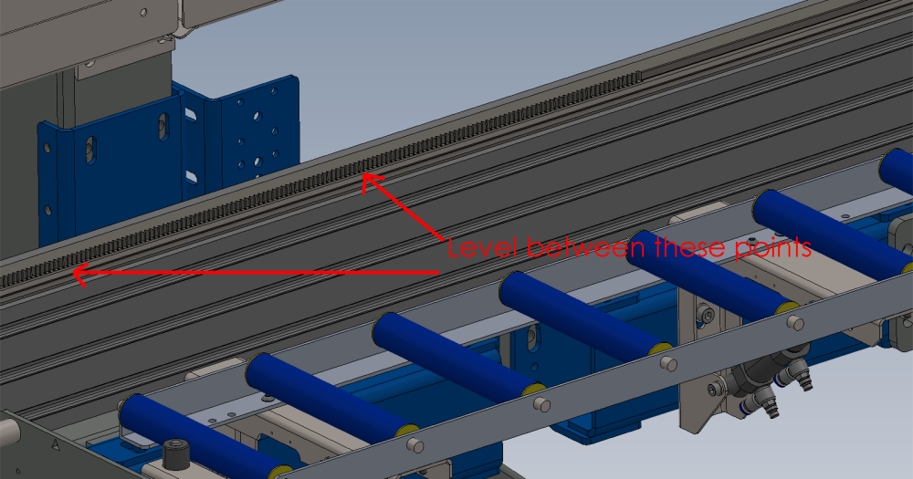
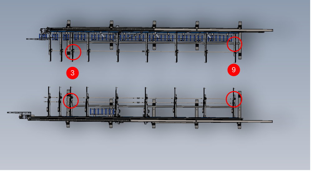
Étape 11 - Add 2 Transfer beams and Parallel set between hepco Rails
- Attach transfer beams 3 and 9 in there locations
- Add fasteners to beams to secure but leave loose enough for adjustment
- Measure the distance between the 2 hepco rails at the points shown on diagram 2 . Both indicated measurements should be the same . If not the slot in the transfer beam can be used to allow adjustment of this measurement to correct . Tolerance -+ 1mm
- Tighten transfer beam fixings to hold frames in correct position
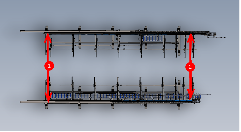
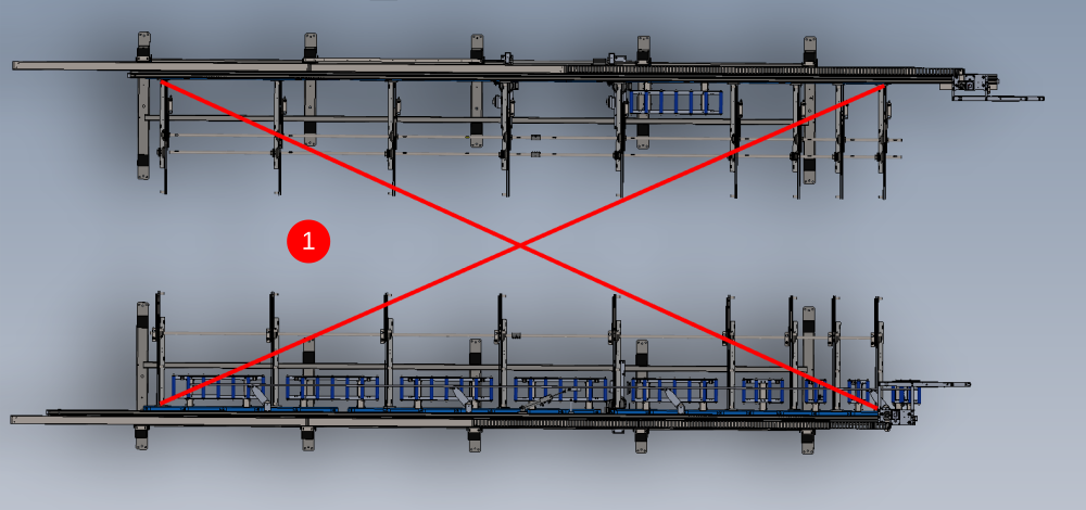
Étape 12 - Check and Set squareness of transfer table
It is crucial to set the squareness of the transfer table by adjusting the infeed/ outfeed tables.
1 The squareness can be checked by using a tape rule to make corner measurements at the points indicated
2 Second frame can be moved in the directions shown to adjust the corner measurements to make them both the same
Tolerance -+ 3mm
R0015291 Install Transfer Beams To Module C and E


Étape 13 - Add remaining transfer beams
Add remaining 7 transfer beams to two installed frames and fix in position on support arms

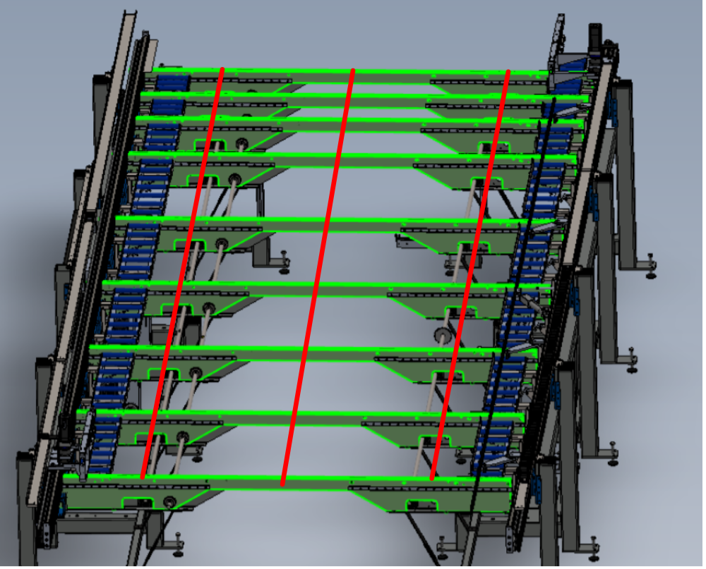
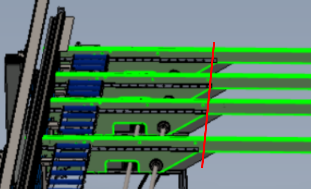
Étape 14 - Check flatness of transfer beam top faces
Once all transfer beams are installed, it is vital to check that the top faces or the transfer beams are all aligned to each other and provide a flat table for correct profile transfer
Use 2 meter straight edge to inspect top faces in relation to each other
Draft
 Français
 English
 Deutsch
 Español
 Italiano
 Português