Bench assembly details for ejector components

Difficulté
Moyen
Durée
0.5 heure(s)
Introduction
Tools Required
Standard hex key set
Parts Required
B0000033 Linear Bearing: Ø20 x 30 Compact (Metal Case Only) x 6
D0004015 Front Slider (5301) x 1
D0004016 Rear Slider x 1
D0004329 Rod End Plate (5304) x 1
D0004420 Extension Linear Block x 2
H0004630 Shaft 20mm: 345 Ejector Crossx 1
Étape 1 - Unless otherwise stated
All bolts to have Loctite 243 adhesive applied unless otherwise stated
All Threaded Pneumatic connections to have Loctite 570 applied
All bolts to be pen marked once adhesive applied and correct tension added

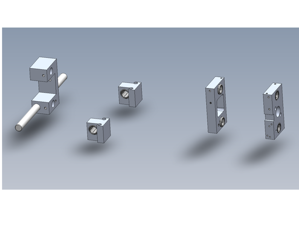
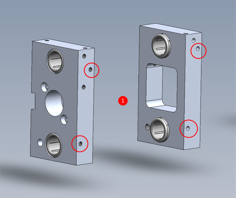
Étape 2 - Assemble slider blocks
D0004015 Front Slider
D0004016 Rear Slider
1 Add M6 x 6 grubscrews to indicated holes, 4 off in total. Use Loctite 570 to seal grubscrews to blocks . Ensure grubscrews sit flush with face of block when fitted. Tap hole deeper with M6 tap to allow grubscrew to sit further in if not possible to achieve flush fitment .
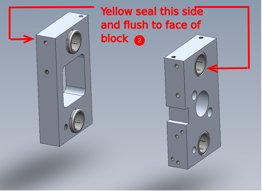
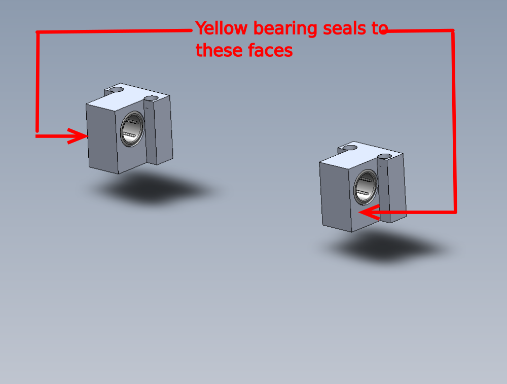
2 Fit 4 off B0000033 Linear Bearing as shown. Ensure yellow face of bearing is fitted on the indicated faces
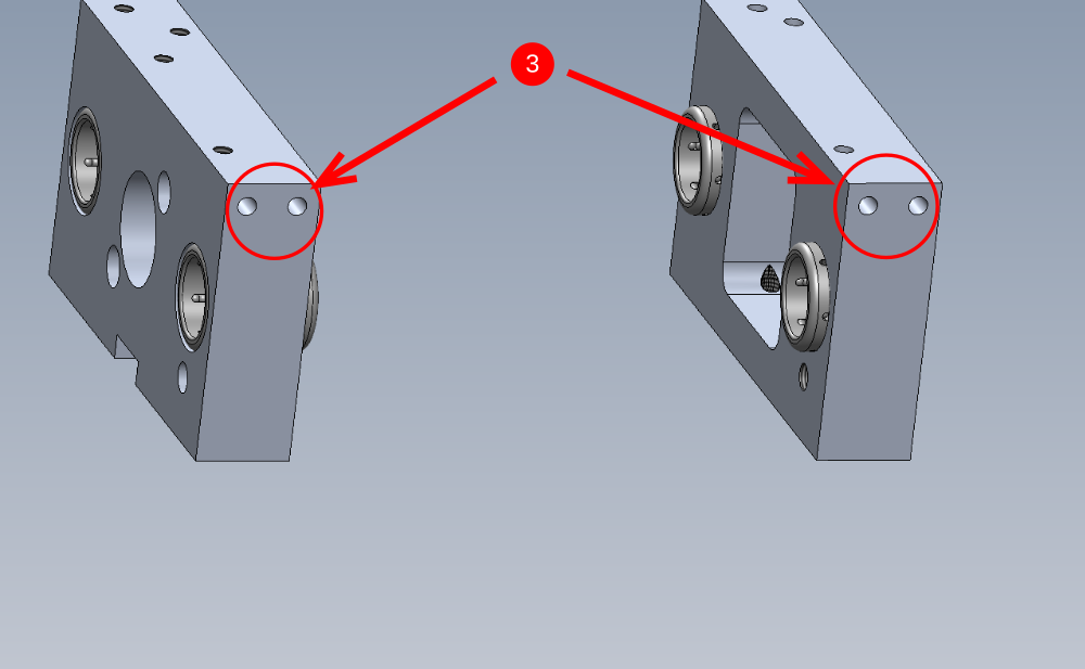
3 Fit 4 off M6 straight grease nipples to indicated points (2 per slider)
Étape 3 - Assemble Rod end plate
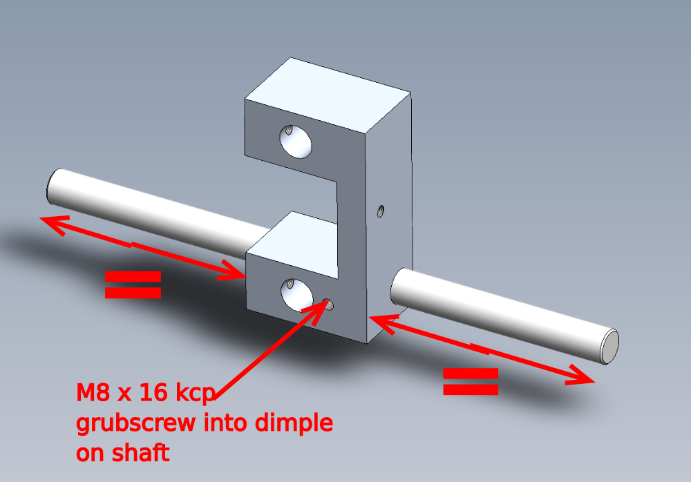
Insert H0004630 Shaft 20mm: 345 Ejector Cross x 1 into D0004329 Rod End Plate (5304) as shown
Dimple in shaft is offset, when correctly fitted, shaft is equally protruding either end of block
Secure with M8 x 16 kcp grubscrew, ensuring dimple is entered by the grubscrew
Étape 4 - Extension blocks
Fit 2 of B0000033 Linear Bearing to 2 off D0004420 Extension Linear Block
Ensure yellow seals are facing the shown direction
Apply liberal grease to these bearings
Draft
 Français
 English
 Deutsch
 Español
 Italiano
 Português