Fitting and setting details for back fences
Introduction
Tools Required
Standard hex key set
1 Meter straight edge
Feeler gauges
engineers square
Shim pack
Parts Required
R0000559 Bench assemble machined parts
R0015326 Bench Assemble Roller Backfences
Étape 1 - Unless otherwise stated
Use locktite 243 on all fasteners
Use loctite 572 on all threaded pneumatic connection
Pen mark all fasteners to show finalised
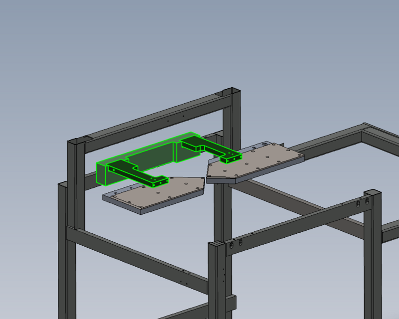
Étape 2 - Attach backfence support
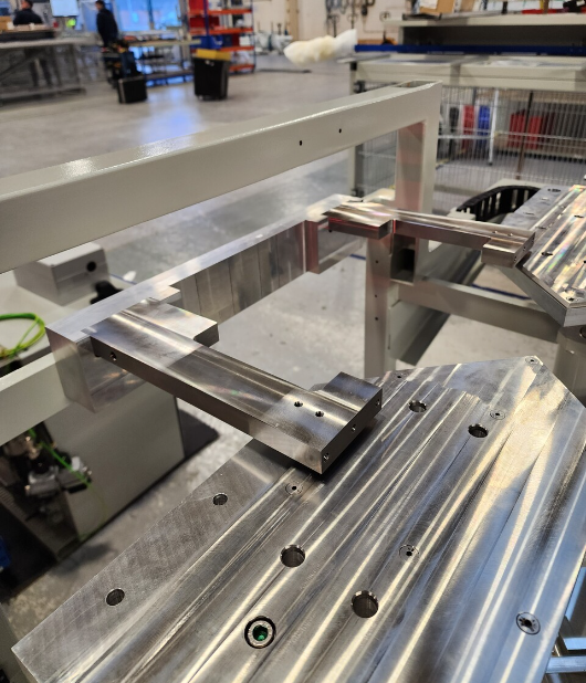
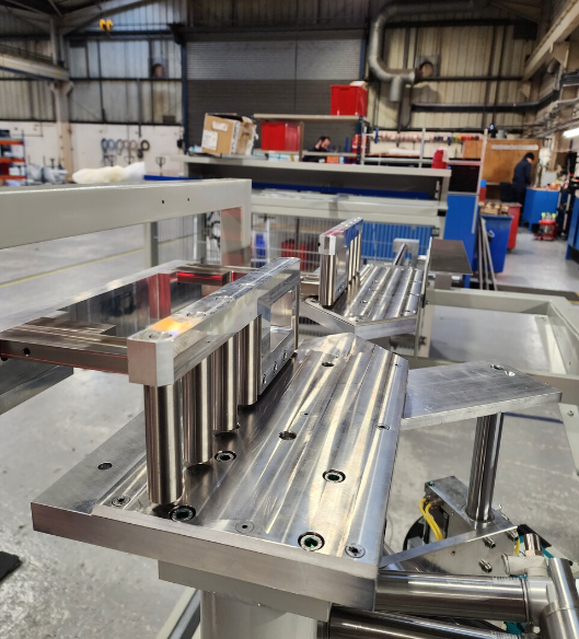
Attach pre machined back fence support to main frame
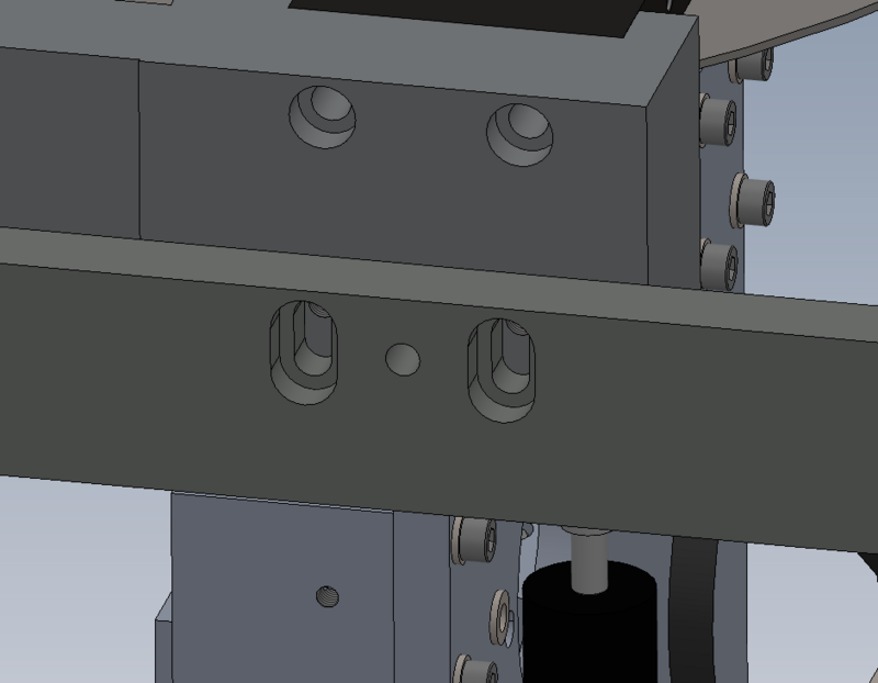
Use 4 off M8 x 25 socket caps , do not apply adhesive
Set assembly to maximum height position in fixing slots
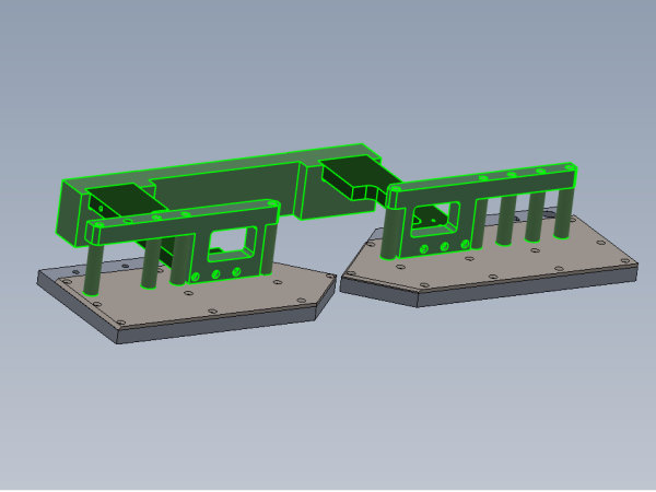
Étape 3 - Attach roller fences
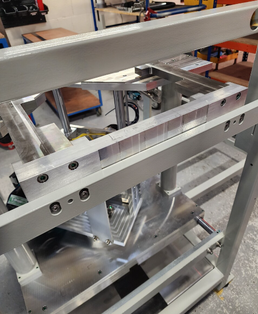
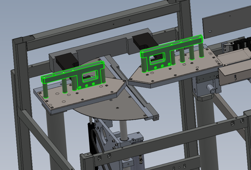
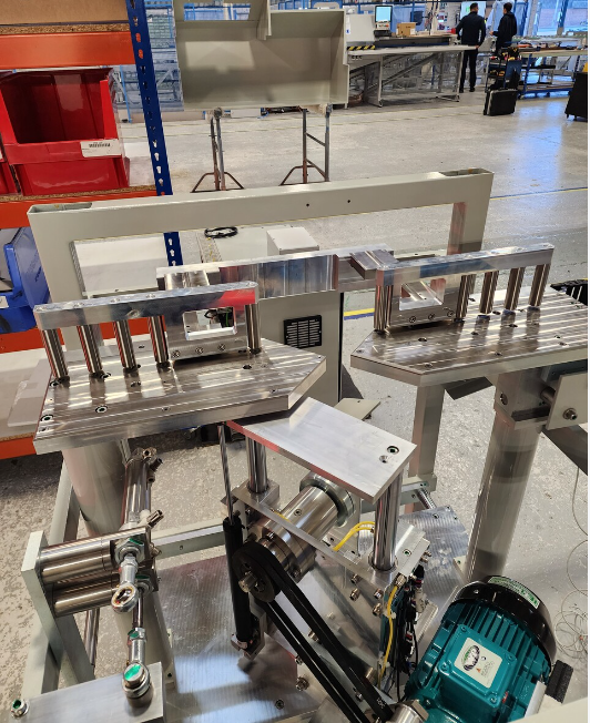
Attach pre build roller fences to backfence support bar using M6 x 35 socket caps . Do not apply adhesive
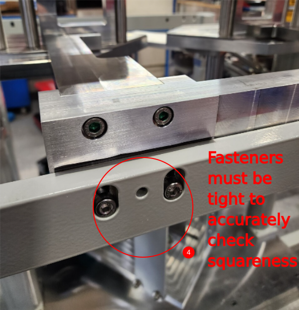
Étape 4 - Set squareness
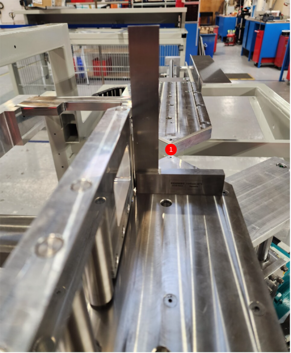
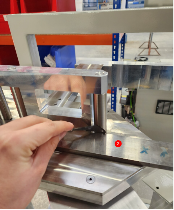
1 Use engineers square to check squareness of roller fences to cut tables. Check at multiple points
2 Identify movement required to adjust square.
Gap between square and roller:
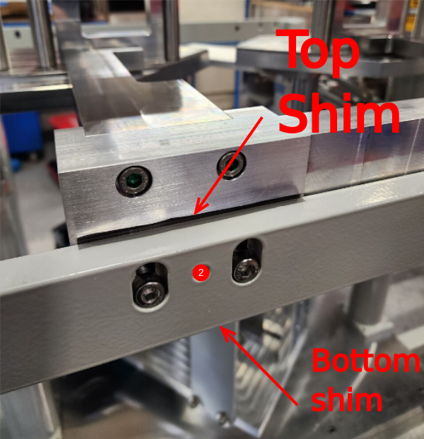
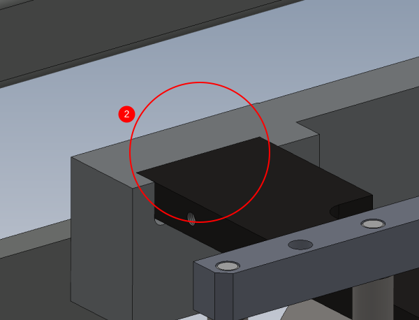
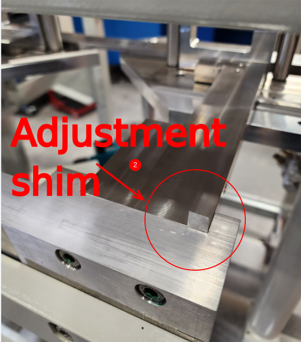
Top = add shim to top of bar
Bottom = Add shim to bottom of bar
3 Cut and add shim ensuring shim bottoms out on M8 fastener, as this will act as a datum
4 Adjust until rollers are square with full tension on M8 fixings
Étape 5 - Set alignment between roller fences
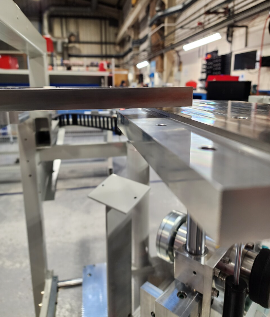
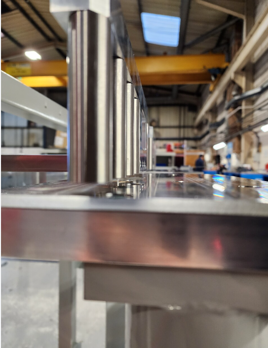
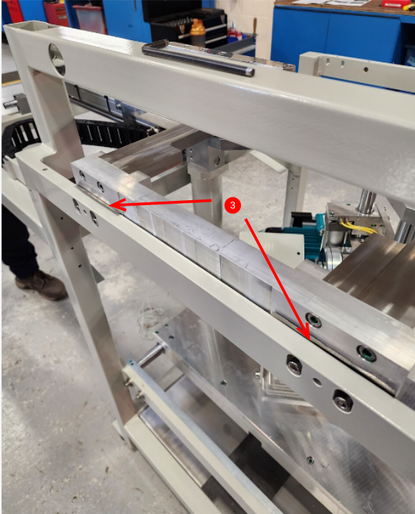
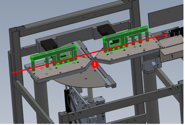
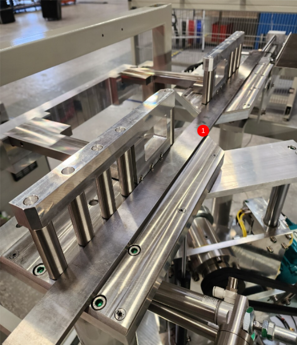
1 Use 1 meter straight edge to check alignment of rollers. Identify which direction movement is required to achieve alignment of all rollers.
Tolerance 0.002"/0.05mm
2 Adjust using shim at indicated point on either / both arms
3 Adjust until all roller are within tolerance to straight edge
Étape 6 - Set height
1 Set heights of all rollers to cut tables to a gap of 1.5 mm . tolerance -+0.5mm at
Étape 7 - Recheck all settings
Once final adjustment has been done, recheck all settings as movement is possible when adjusting
Table /roller squareness
Roller alignment
Roller height
Finalise all bolts
Draft


 Français
 English
 Deutsch
 Español
 Italiano
 Português