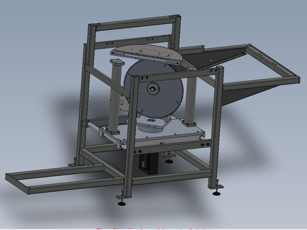
Assembly details for fitment of main saw head and spindle posts

Difficulté
Difficile
Durée
1 minute(s)
Introduction
Tools Required
Standard hex key set
Standard flat hand file
Emery tape 120
standard hand tap set
Stubby hex key set
Ratchet/hex bit set
Blade flange spanner
Parts Required
D0004002 Webb x 1
D0004003 Top Shaft Block x 2
D0004004 Brace Support Bar (D7451) x 1
D0004157 Motor plate spacer x 3
D0004342 Damper Bracket (5312) x 1
D0007451 Brace Support Bar OH (D4004) x 1
D0015490 Saw Turntable Sensor Flag x 1
D0015491 Saw Turntable Flag Bracket x 1
H0004024 Infeed Clamp Post x 1
H0004025 Outfeed Clamp Post (5302) x 1
H0004510 Shaft 30mm: 540 Saw Stroke x 2
P0000055 Adjustable Damper 200mm (Saw Stroke) x 1
R0000560 Bench Assemble Spindle x 1
R0000569E Bench Assemble Head Spindle Posts Mk5 x 1
V0000043B Saw Blade: Ø500 x 160 teeth x 3.2mm pl x 4mm kf x 30mm bore x 1Étape 1 - Unless otherwise stated
All bolts to have Loctite 243 adhesive applied unless otherwise stated
All Threaded Pneumatic connections to have Loctite 570 applied
All bolts to be pen marked once adhesive applied and correct tension added

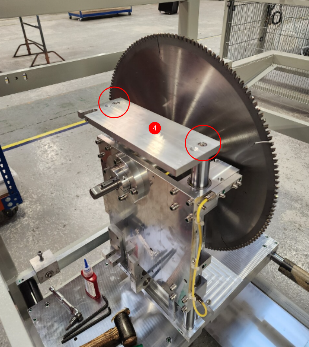
Étape 2 - Fit damper bracket
Fit Damper bracket to top of shafts using 2 off M8 x 20 socket caps. Do not apply adhesive and only add light tension to these bolts


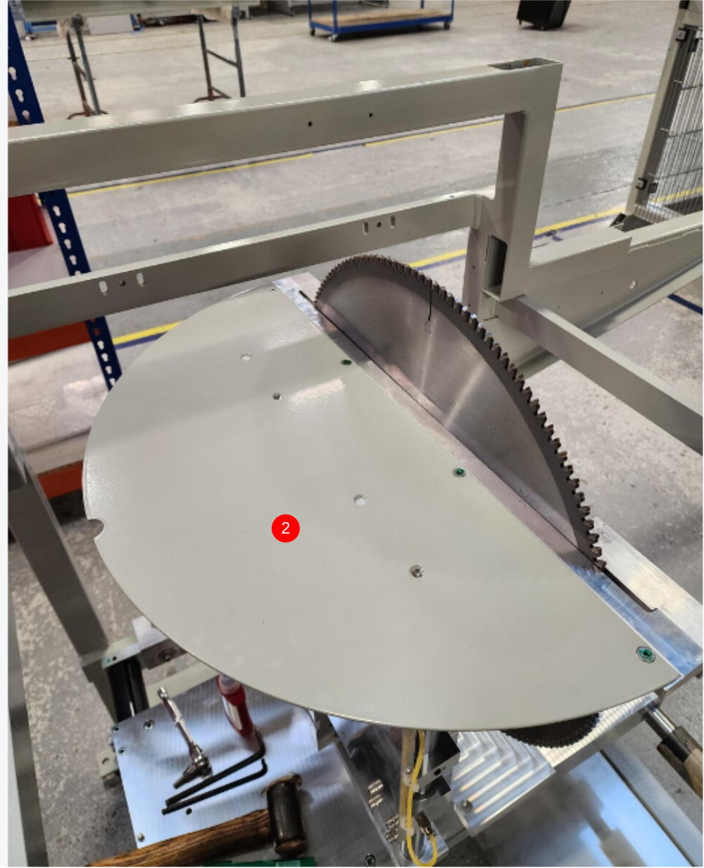
Étape 3 - Fit pre assembled Guard
1 Support upstroke plate in extended position
2 Fit guard using 2 off M5 16 countersunk hex bolts
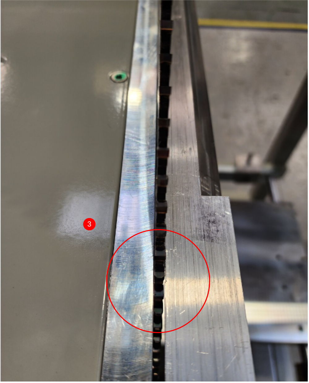
3 Adjust damper bracket position to centralise guard on saw blade
4 Remove guard , individual remove and add adhesive to fasters and apply final tension
5 Refit guard and check correct position of guard in relationship to saw blade


Étape 4 - Remove guard and blade
Remove guard and blade and store for later fitting
Removing support jig lifting upstroke plate


Étape 5 - Mount cylinder to head
1 Lightly Fix base of cylinder using 2 off M6 x 20 socket caps
2 Lightly fix bracket on cylinder using 2 off M x 30 socket caps
3 Ensure assembly is in contracted position (Plate dropped under own weight)
4 Finalise tension on fasteners securing cylinder position
5 Move assembly up and down by hand to check correct operation. Movement should be smooth and consistent

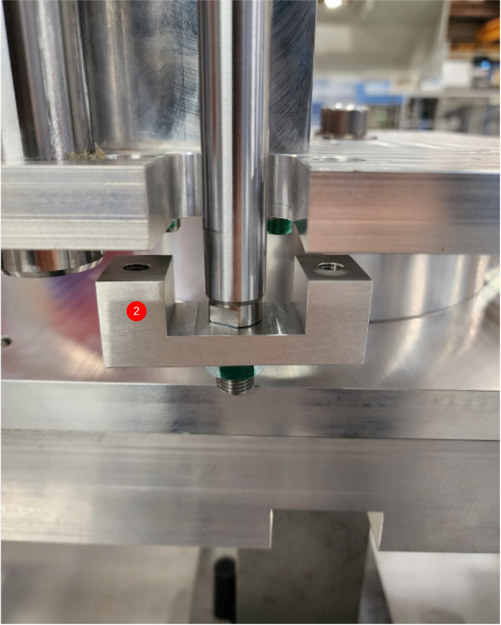
Étape 6 - Attach damper
Pictures required of these steps for creating these pins
1 Use 2 off M6 x 100 socket caps to modify for damper pins
Calculate length and cut bolts to suit , so only shank of bolt is used
2 Calculate FLAT position , and add flat to shank
3 Position lower Damper mount point and add lower pin ,ensuring to align flat on pin with grubscrew and secure with M6 x 10 kcp grubscrew
4 Position upper damper mount point and add pin, ensuring flat on pin aligns with grubscrew and fix with M6 x 10 kcp grubscrew

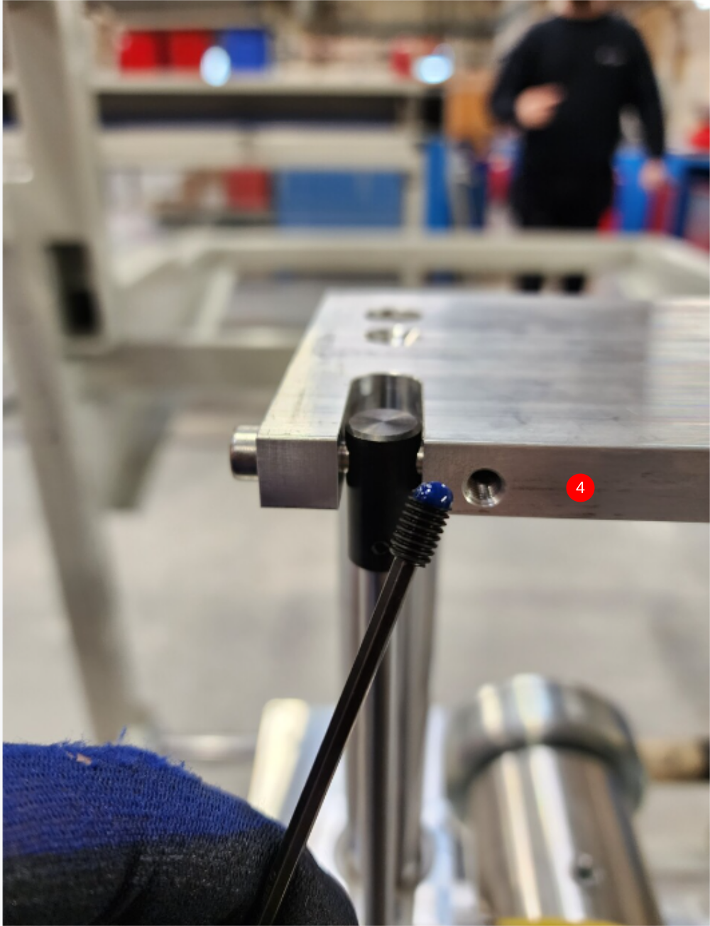
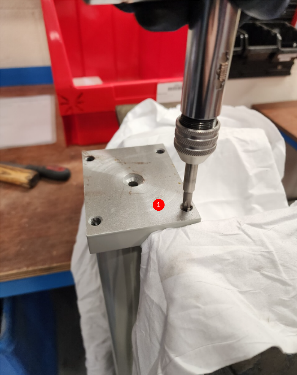
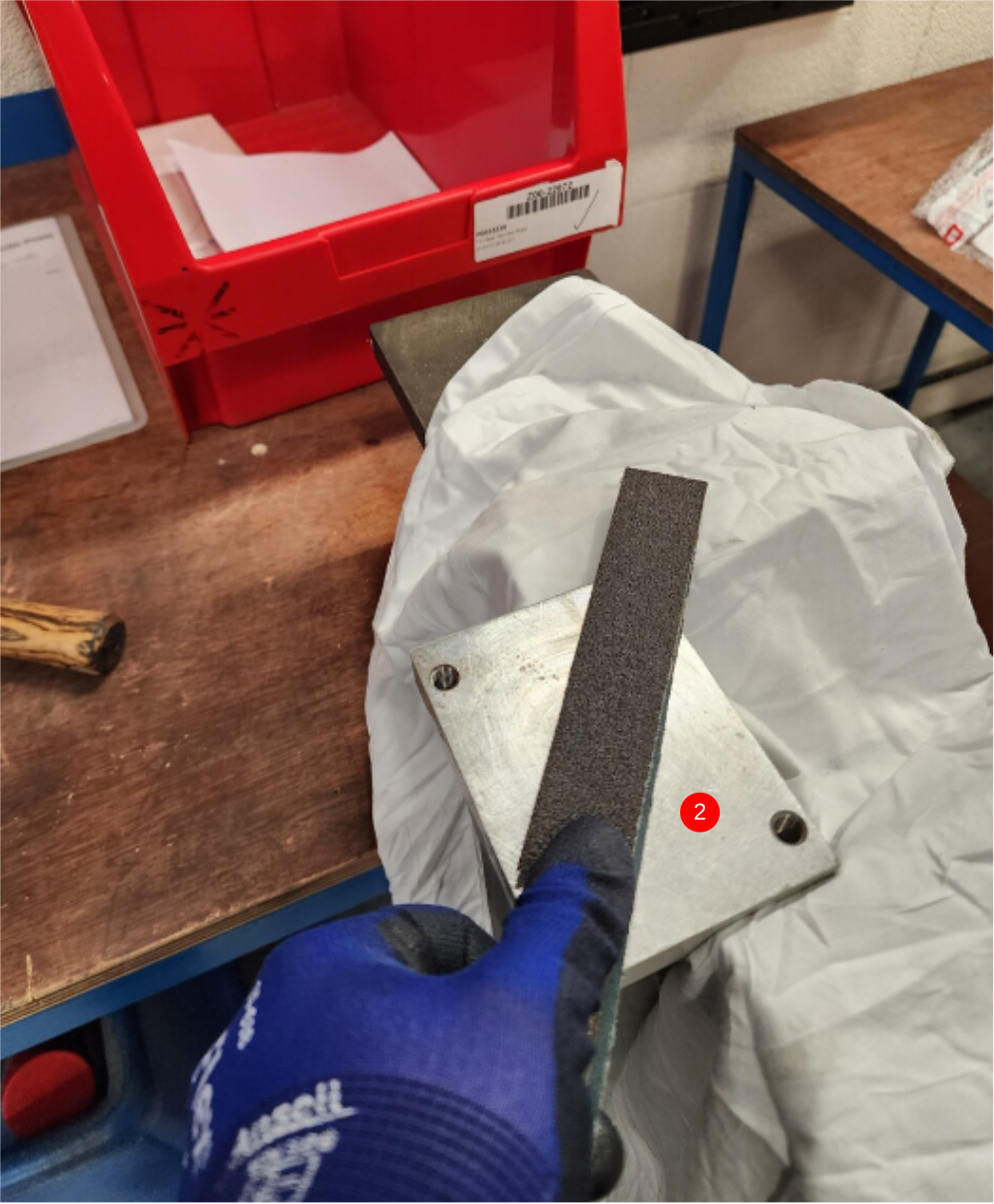
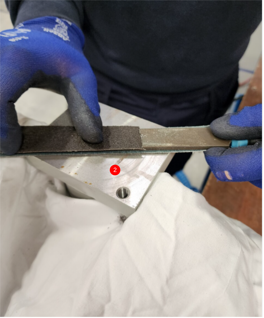
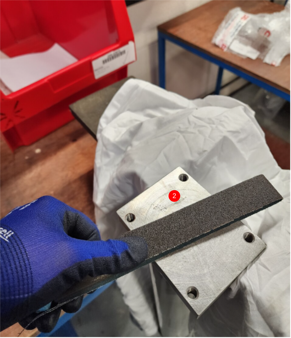
Étape 7 - Prepare posts
1 Tap all holes to remove debris from coating process
2 Dress faces with file and emery tape as shown
3 Clean faces and tapped holes with compressed air and Fe10 solvent
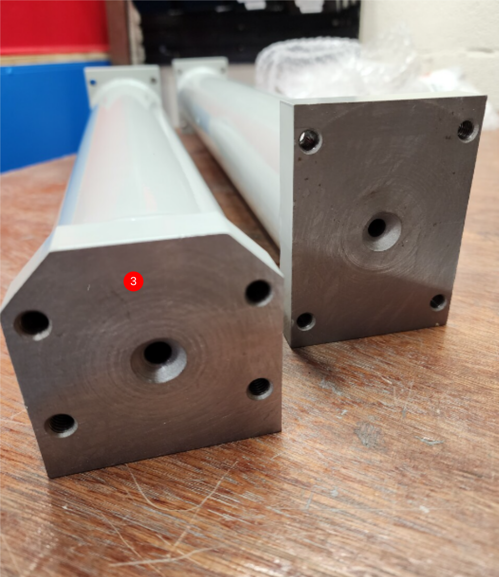
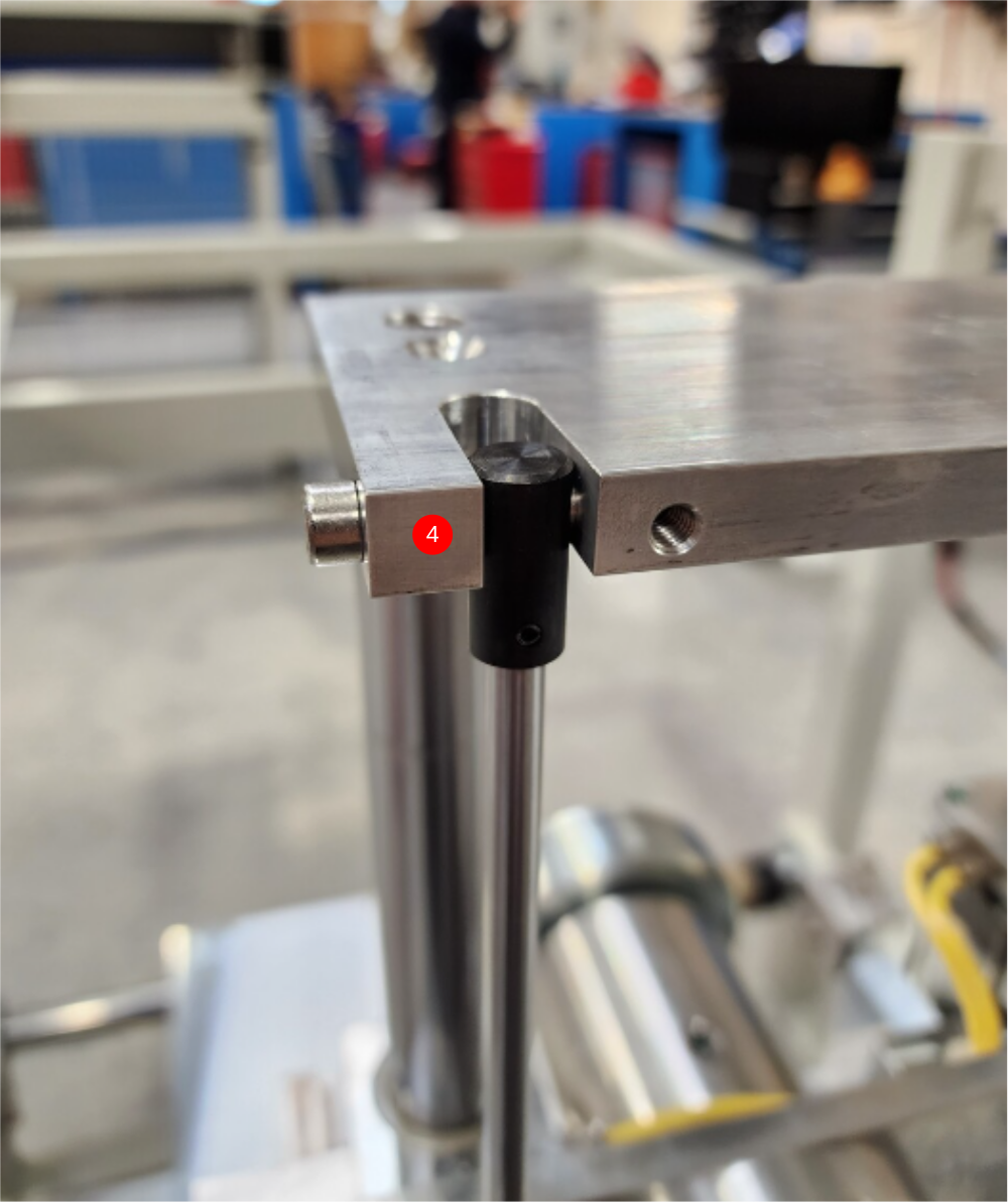
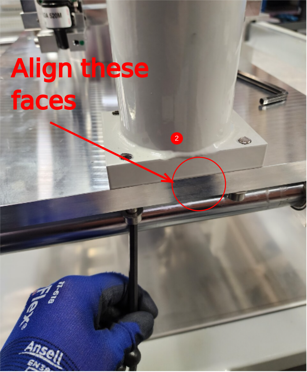
Étape 8 - Fit posts to base
Do not add adhesive to bolts , But add final tension
1 Post positions are as shown
2 Fix posts on pre fitted 2 off socket caps. Then add 2 off M8 x 40 socket caps and A form washers per post . Ensure posts are aligned flush on faces indicated


Draft
 Français
 English
 Deutsch
 Español
 Italiano
 Português