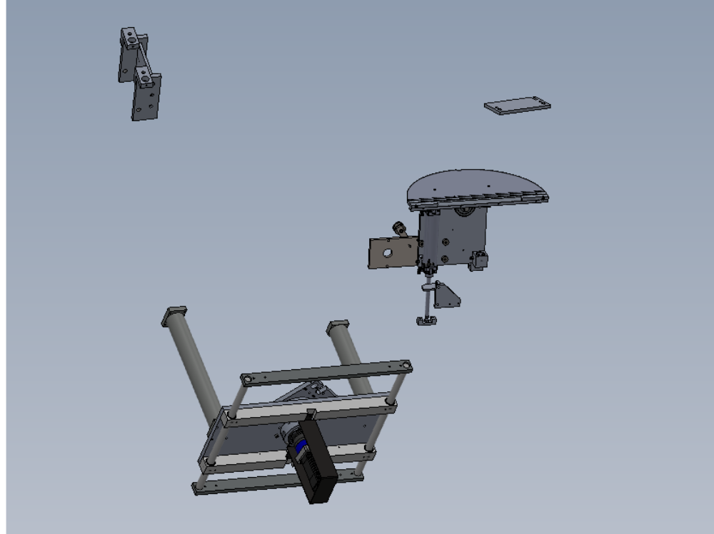
Assembly details for fitment of main saw head and spindle posts

Difficulté
Difficile
Durée
3 heure(s)
Sommaire
- 1 Introduction
- 2 Étape 1 - Unless otherwise stated
- 3 Étape 2 - Attach brace supports
- 4 Étape 3 - Fit web
- 5 Étape 4 - Fit shafts
- 6 Étape 5 - Fit pre assembled head
- 7 Étape 6 - Fix top shaft blocks
- 8 Étape 7 - Finalise bearing blocks
- 9 Étape 8 - Fit spindle
- 10 Étape 9 - Fit motor plate and sr flags
- 11 Étape 10 - Fit saw blade
- 12 Étape 11 - Fit damper bracket
- 13 Étape 12 - Assemble guard and slit strips
- 14 Étape 13 - Fit guard
- 15 Étape 14 - Remove slit strip guard
- 16 Étape 15 - Assemble Cut cylinder
- 17 Étape 16 - Mount cylinder to head
- 18 Étape 17 - attach saw damper
- 19 Étape 18 - Prepare posts
- 20 Étape 19 - Fit posts
- 21 Commentaires
Introduction
Tools Required
Standard hex key set
Standard flat hand file
Emery tape 120
standard hand tap set
Parts Required
D0004002 Webb x 1
D0004003 Top Shaft Block x 2
D0004004 Brace Support Bar (D7451) x 1
D0004157 Motor plate spacer x 3
D0004342 Damper Bracket (5312) x 1
D0007451 Brace Support Bar OH (D4004) x 1
D0015490 Saw Turntable Sensor Flag x 1
D0015491 Saw Turntable Flag Bracket x 1
H0004024 Infeed Clamp Post x 1
H0004025 Outfeed Clamp Post (5302) x 1
H0004510 Shaft 30mm: 540 Saw Stroke x 2
P0000055 Adjustable Damper 200mm (Saw Stroke) x 1
R0000560 Bench Assemble Spindle x 1
R0000569E Bench Assemble Head Spindle Posts Mk5 x 1
V0000043B Saw Blade: Ø500 x 160 teeth x 3.2mm pl x 4mm kf x 30mm bore x 1
Étape 1 - Unless otherwise stated
All bolts to have Loctite 243 adhesive applied unless otherwise stated
All Threaded Pneumatic connections to have Loctite 570 applied
All bolts to be pen marked once adhesive applied and correct tension added

Étape 2 - Attach brace supports
attach brace supports to turntable plate
ensure correct one is dowelled

Étape 3 - Fit web
Fit web, use to set pitch of brace supports, and set both to same edge distance then finalise fasteners on brace supports and web

Étape 4 - Fit shafts
Fit shafts to turntable plate

Étape 5 - Fit pre assembled head
Fit pre assembled head in conjunction with 2 off top shaft blocks

Étape 6 - Fix top shaft blocks
Add fasteners to top shaft blocks and position evenly
Étape 7 - Finalise bearing blocks
Finalise bearing block fasteners ensuring correct alignment

Étape 8 - Fit spindle
Attach pre built spindle to main plate

Étape 9 - Fit motor plate and sr flags
Étape 10 - Fit saw blade
Étape 11 - Fit damper bracket

Étape 12 - Assemble guard and slit strips

Étape 13 - Fit guard
Fit assembled slit strips to damper housing and adjust damper bracket to achieve blade clearance between slit strips

Étape 14 - Remove slit strip guard
Remove slit strip assembly
Étape 15 - Assemble Cut cylinder
Assemble cut cylinder with cylinder rod bar and air fittings

Étape 16 - Mount cylinder to head
Attach cut cylinder to assembly ensuring correct alignment

Étape 17 - attach saw damper
Prepare 2 off M6 bolts to act as pins for damper
Fit damper to head assembly
Étape 18 - Prepare posts
Prepare infeed /outfeed posts for fitting
ensure machined faces are cleaned with emery but flatness is maintained (details required)
Ensure tapped holes are cleaned to remove any debris


Étape 19 - Fit posts
Attach posts to base
Details for correct orientation
Do not add adhesive at this point to posts

Draft
 Français
 English
 Deutsch
 Español
 Italiano
 Português