Method for levelling bare frames for modules A,C and F for ZX5/3 Preparing frame for production
Introduction
Tools Required
Standard taps set
standard spanner set
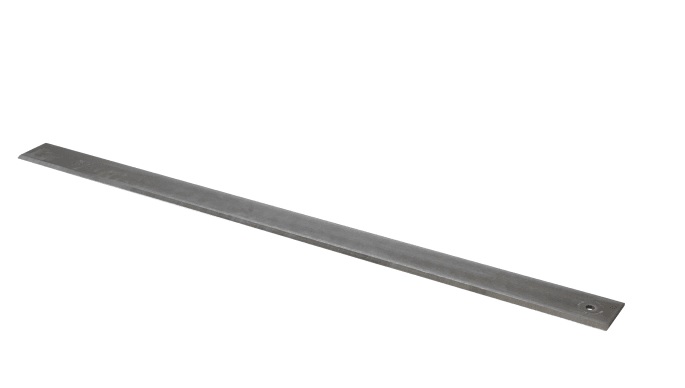
2 meter straight edge
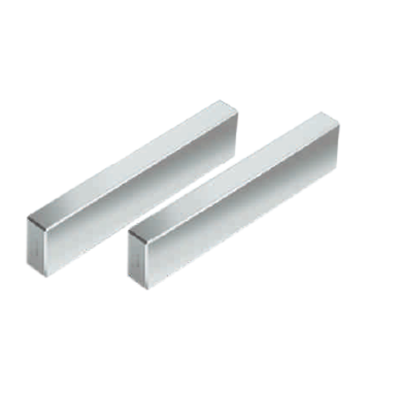
1" parallel blocks
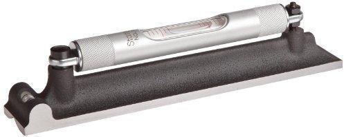
300mm engineers level
Parts Required
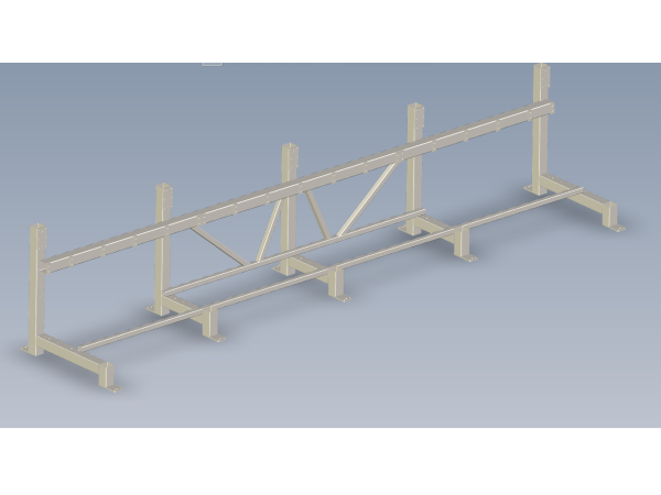
D0015265 Frame
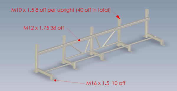
M0000224 100x 100 frame cap 10 off
F0000234 M16 x 1.5 nut 10 off
F0000266 M16 x 1.5 set bolt x 10 offÉtape 1 - Clean all tapped threads on frame
Tap all holes to remove debris from coating process
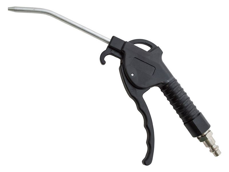
Ensure all holes cleaned after tapping with compressed air
Étape 2 - Add jacking bolts
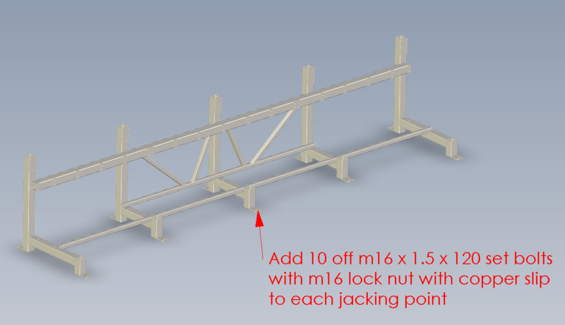
Fit 10 off m16 x 1.5 x 120 set bolts with standard m16 x 1.5mm nut and copper slip to lubricate lock nut and thread into frame.
Étape 3 - Add levelling pads
Use a pallet truck to lift frame.
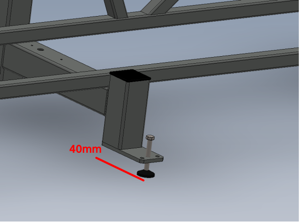
Wind through M16 bolts until approximately 40mm protrusion from below base of foot
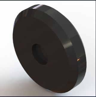
Locate each bolts into black nylon levelling pad
Étape 4 - Level Y axis
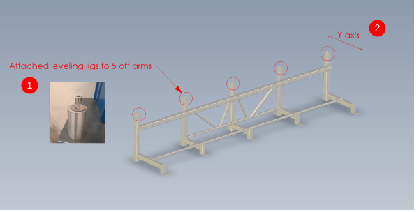
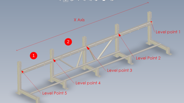
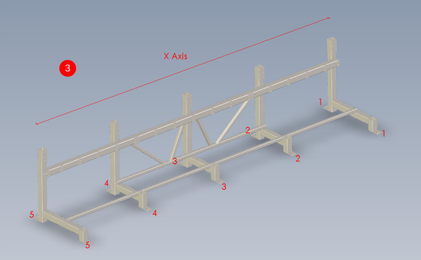
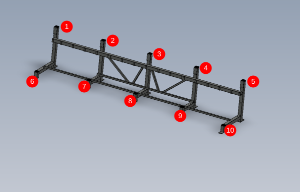
1 Attach levelling jigs to 5 points across frame
2 Use level on jig to indicate current state of level
3 Check across all 5 points to identify where to lift frame to achieve level
4 Lift frame by jacking bolts to achieve level on level jigs
5 Adjust level on Y axis until all level points are correct.
Étape 5 - Level x axis
1 Place one parallel at point 1 and 1 parallel at point 2. Span these with a 2mtr straight edge and use engineers level on top of straight edge to show current level
2 Repeat this between point 2 and 3 , then 3 and 4 and finally 4 and 5. This will highlight the movement required to level frame
3 Use the same method as the Y axis
4 achieve all points 1-5 level , any discrepancy should be reported to the Supervisor
Étape 6 - Fit frame endcaps
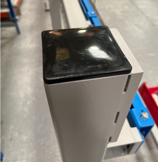
Frame end caps will now need fitting to frame
10 off M0000224 fitted to all open cavities of 100mm square box section
Draft

 Français
 English
 Deutsch
 Español
 Italiano
 Português