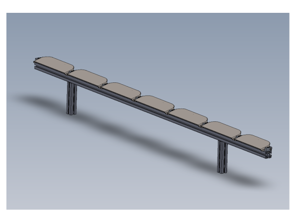
Bench assembly details for sensor rail
Sommaire
- 1 Introduction
- 2 Étape 1 - Unless otherwise stated
- 3 Étape 2 - Quality check
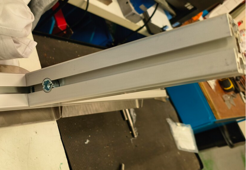
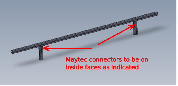
- 4 Étape 3 - Assemble Maytec frame
- 5 Étape 4 - Fit bushes
- 6 Étape 5 - Fit 1st Pivot
- 7 Étape 6 - Add dowel
- 8 Étape 7 - Fit 1st plate
- 9 Étape 8 - Fit 2nd plate
- 10 Étape 9 - Repeat for remaining plates
- 11 Étape 10 - Fit sensors
- 12 Étape 11 - Fit tie bases
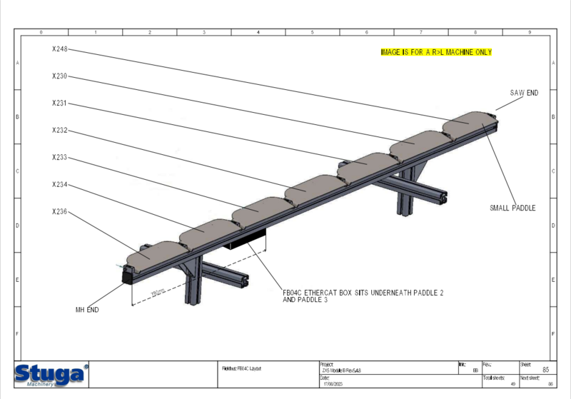
- 13 Étape 12 - Assemble and mount Ethercat box
- 14 Étape 13 - Fit support angles
- 15 Étape 14 - Quality check
- 16 Étape 15 - Electrical connections if requested
- 17 Commentaires
Introduction
Tools Required
Standard hex key set
Parts Required
B0001099 Bush flange 10 i/d 12 o/d x 14
C0001018 EP2338-0001 EtherCAT Box 8 Configurable IO x 1
D0010167 Ethercat Mount Plate x 1
D0015353 Sensor Flapper Pivot x 8
D0015355 Sensor Flapper Plate (312) x 6
D0015357 Sensor Flapper Plate (270) x 1
D0015363 Sensor Flapper Support Transfer SEE NOTE x 1
E0000336L Sensor: M8; 4mm, PNP N/O, M8 conn x 7
F0000537 dowel pin 10 x 40 x 8
M0001016 Angle 74 x 38 x 2
M0001209 Bracket m8 proximity sensor bracket 90 deg x 7
Étape 1 - Unless otherwise stated
Use Loctite 243 on all fasteners
Use Loctite 570 on all threaded pneumatic connections
Pen mark all bolts when finalised
Étape 2 - Quality check
Check components
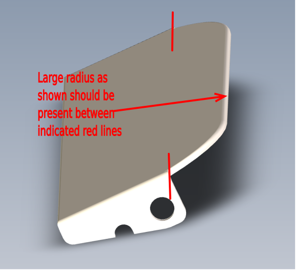
D0015355 Sensor Flapper Plate (312) x 6
D0015357 Sensor Flapper Plate (270) x 1
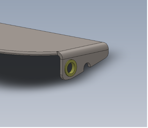
1 Ensure indicated have a radius on the indicated faces and are smooth and burr free
2 Ensure apex is flattened off, use linisher if required. This step is required to enable correction function of paddles
Étape 4 - Fit bushes
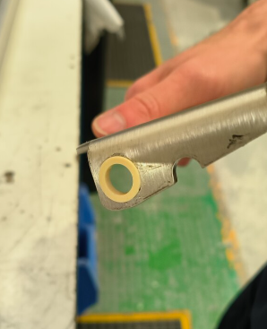
Fit B0001099 Bush flange 10 i/d 12 o/d x 14 into D0015355 Sensor Flapper Plate (312) x 6 and D0015357 Sensor Flapper Plate (270) x 1 as shown
Étape 5 - Fit 1st Pivot
Fit 1st D0015353 Sensor Flapper Pivot as shown
Fix with F0000299 m6 d nut and M6 x 20 socket cap
Étape 6 - Add dowel
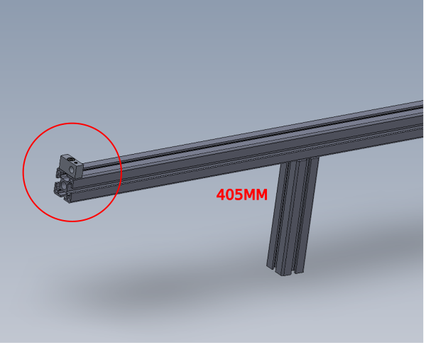
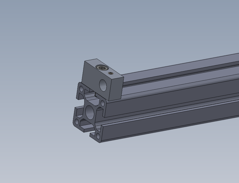
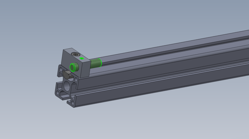
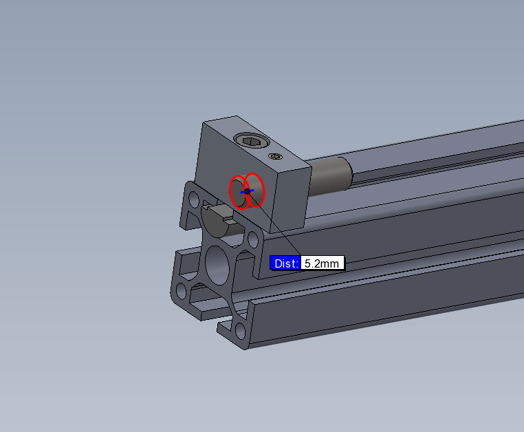
Fit F0000537 dowel pin 10 x 40 as shown, leaving 5mm of protrusion
Secure with M5 x 6 kcp grubscrew
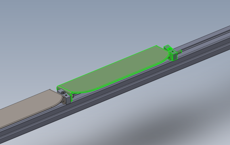
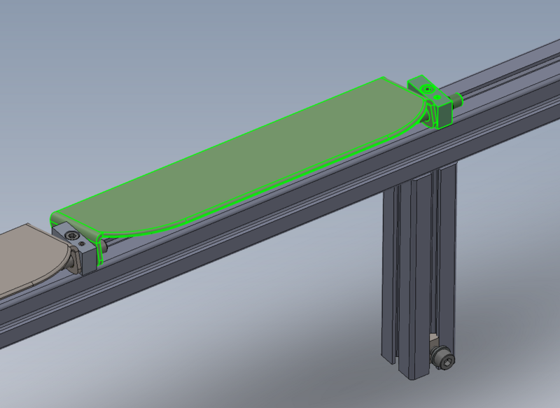
Étape 7 - Fit 1st plate
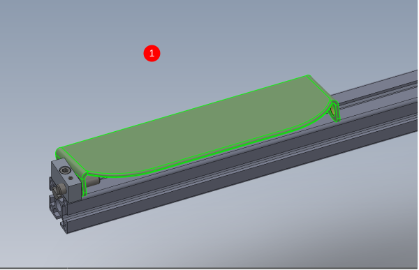
1 Position as shown D0015357 Sensor Flapper Plate
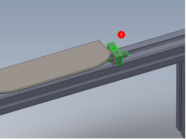
2 Captivate with pivot block and dowel as shown, using same fixings as previous pivot block . Ensure dowel sits central in pivot block.
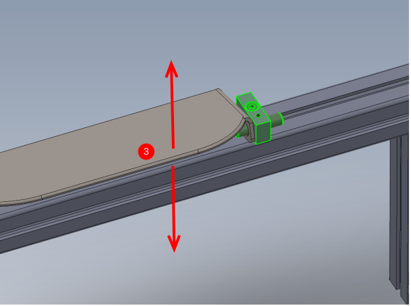
3 Ensure sensor plate is free to move in the direction shown when fitted. Leave as minimal gap as possible between pivot blocks and sensor plate
Ensure sensor plate drops back under its own weight
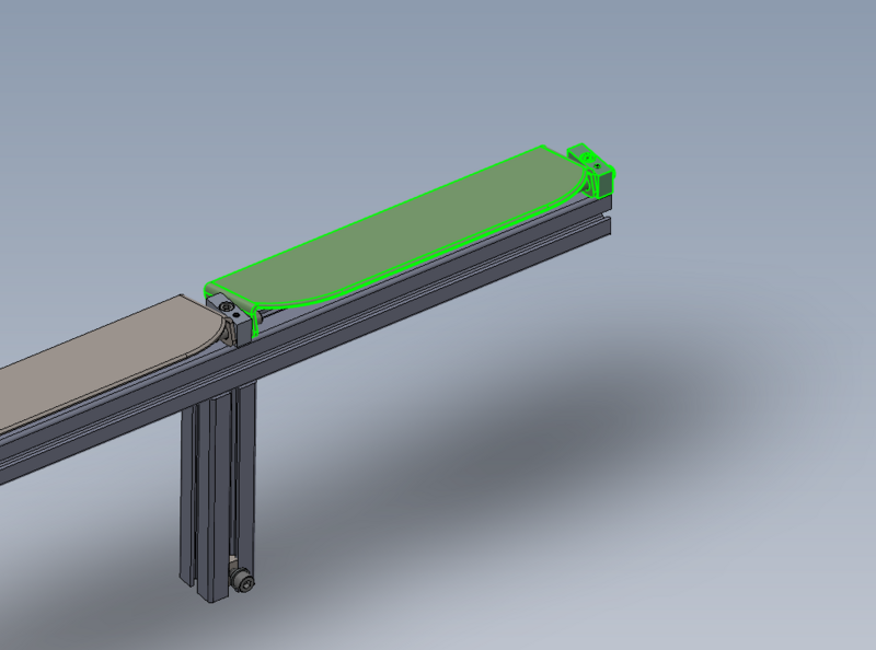
Étape 8 - Fit 2nd plate
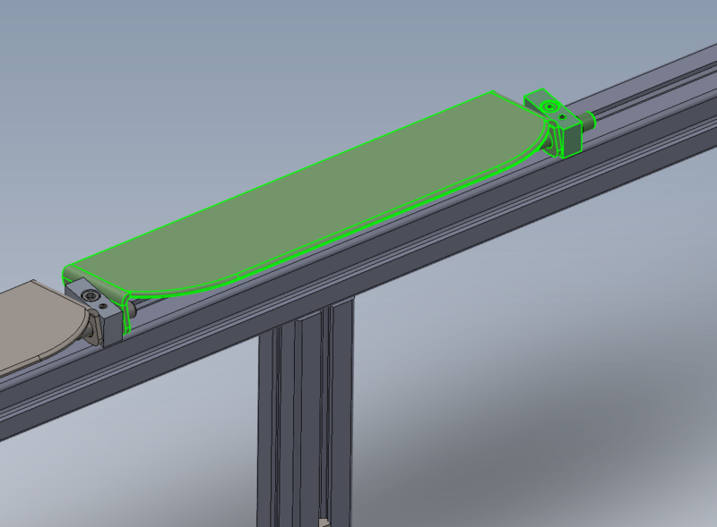
Fit D0015355 Sensor Flapper Plate (312) and fix with same method as previous steps
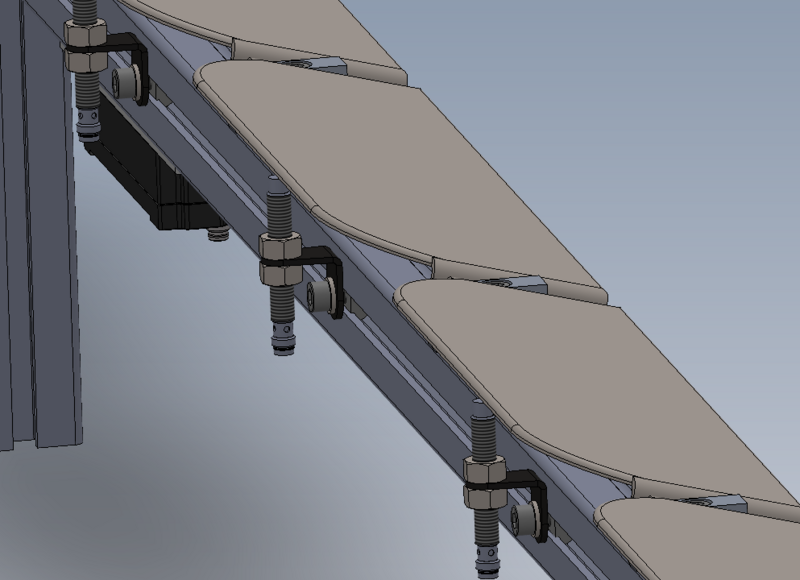
Étape 10 - Fit sensors
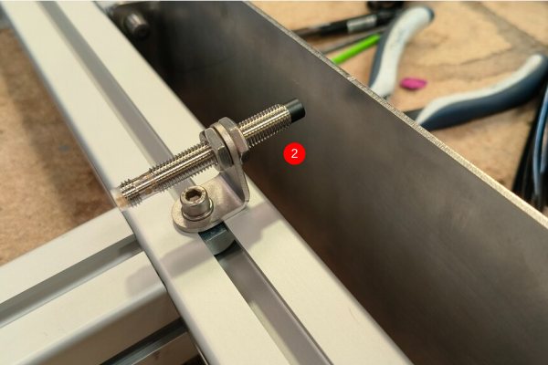
Ensure sensors are fitted to the correct side of the sensor paddles. Sensors should be fitted to the radius side as shown
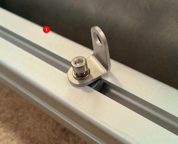
1 Fit 7 off M0001209 Bracket m8 proximity sensor bracket 90 deg. Position each bracket centrally beneath each sensor plate and orientate as shown
Use M5 fat D nut, M5 x 10 socket cap and A form washer to secure
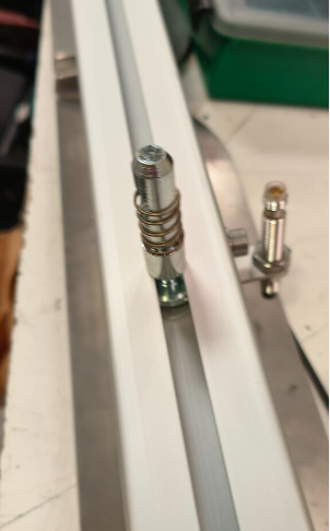
2 Fit 7 off E0000336L Sensor: M8; 4mm, PNP N/O, M8 conn as shown .
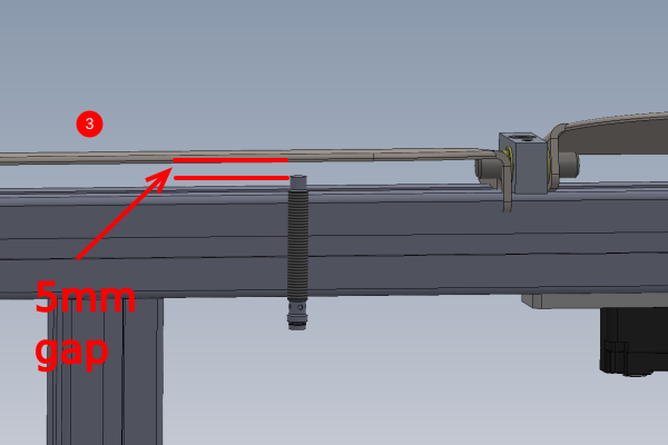
3 Set sensor gap to 5mm
With the sensor plate fully depressed in the direction shown, set sensor so 5mm gap is present
4 Secure 2 off lock nuts on sensor. Caution do not over tension, as this can lead to damage to sensor !
Étape 11 - Fit tie bases
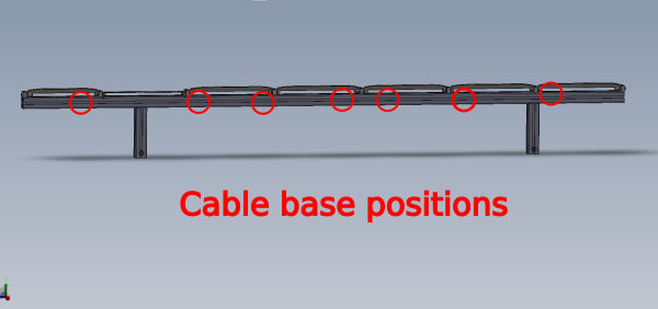
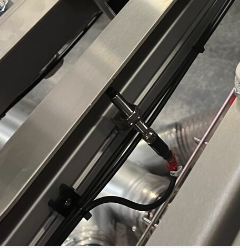
Fit Cable tie bases using M5 x 10 button sockets an M5 fat D nuts at the positions shown
(cables shown are fitted at a later stage)
Étape 12 - Assemble and mount Ethercat box
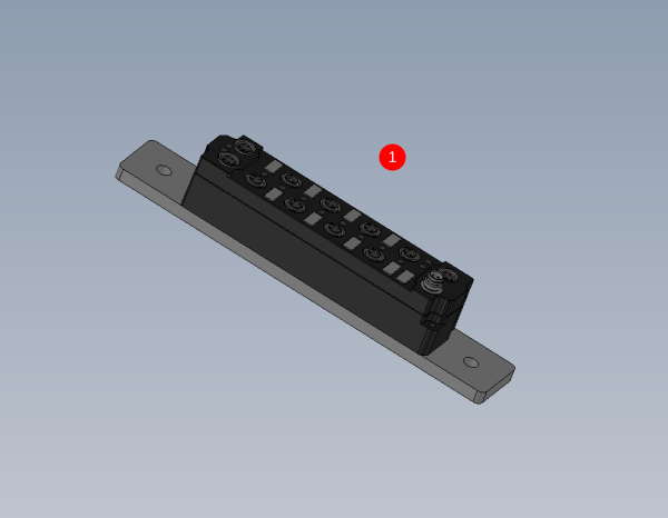
1 Assemble C0001018 EP2338-0001 EtherCAT Box 8 Configurable IO onto D0010167 Ethercat Mount Plate x 1 as shown using M3 x 20 pan head fasteners
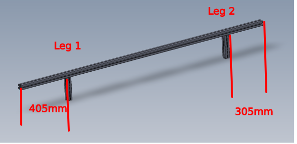
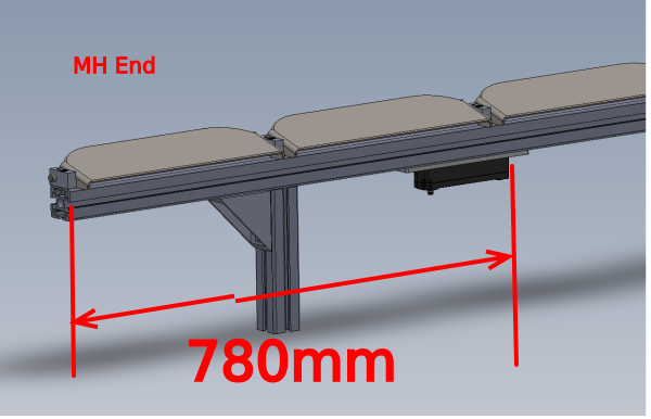
2 Fit to assembly Using 2 off M6 fat D nuts , M6 x 16 socket caps and A form washers at the position shown of 780 mm from indicated face to edge of ethercat box
Étape 13 - Fit support angles
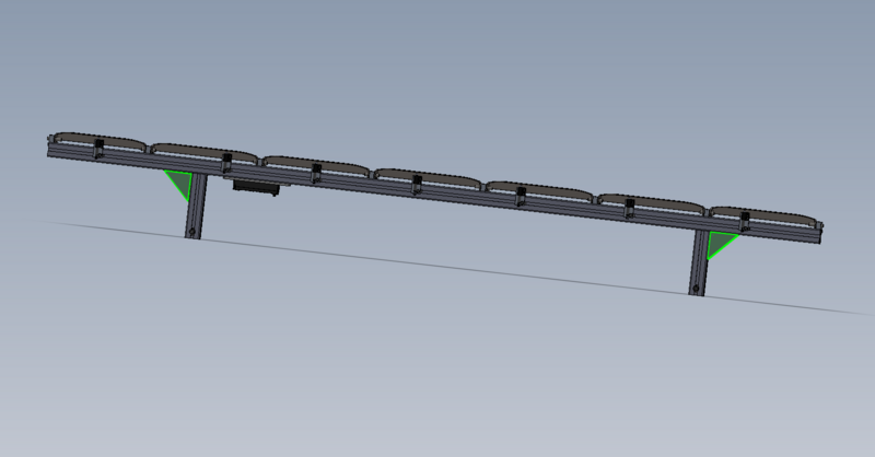
Fit 2 off M0001016 Angle 74 x 38 as shown
Fasten with M8 Fat D nut, M8 x 20 socket cap and Heavy M8 motor plate washers
Étape 14 - Quality check
Ensure all fasteners are double checked for correct tension, adhesive and identification to show finalised
Draft


 Français
 English
 Deutsch
 Español
 Italiano
 Português