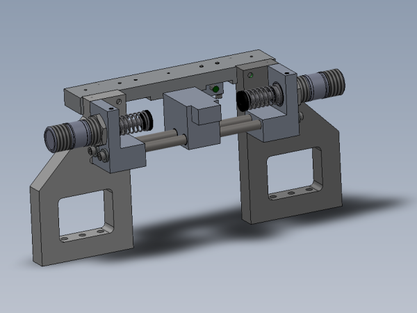
Bench assembly details for R axis limit stop
Sommaire
- 1 Introduction
- 2 Étape 1 - Unless otherwise stated
- 3 Étape 2 - Fit bushes
- 4 Étape 3 - Assemble damper stop housings
- 5 Étape 4 - Insert shafts and slide finger
- 6 Étape 5 - Fit Cross joiner
- 7 Étape 6 - Fix shafts
- 8 Étape 7 - Quality check
- 9 Étape 8 - Fit dampers
- 10 Étape 9 - Damper setting
- 11 Étape 10 - Fix datum sensor block
- 12 Étape 11 - Set Sensor
- 13 Étape 12 - Ensure all bolts are finalised
- 14 Commentaires
Introduction
Tools Required
Standard hex key set
38mm spanner
Parts Required
B0000122 Glacier Bush 12 D 14 D 15 Long x 4
D0007454 Stop Sub Base OH (D8377) x 1
D0007455 Stop Damper Housing OH (D8378) x 1
D0008377 Stop Sub Base (D7454) x 1
D0008378 Stop Damper Housing (D7455) x 1
D0008380E Stop Slide Finger ZX4 Mk5 x 1
D0008383 Cross Joiner x 1
D0010756 Proximity Switch Mounting Block Reduced Size x 1
E0000336 Sensor: M8; 2mm, PNP N/O, M8 conn x 1
H0008379 Shaft 12mm: 263mm R Axis Limit Stainless x 2
P0000235 MC Series self compensating Damper x 2
Étape 1 - Unless otherwise stated
All bolts must have Loctite 243 adhesive applied unless otherwise stated.
All bolts must be marked with pen once completed to indicate adhesive and correct tension has been applied
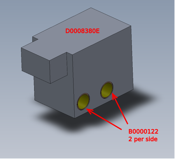
Étape 2 - Fit bushes
Fit 4 off B0000122 bushes to block D0008380E as shown
Bushes must be pushed flush to face
Check internal diameter of bushes once fitted by using 1 off H0008379 Shaft 12mm
If fit is tight, use 12mm hand reamer to clean bore to 12mm
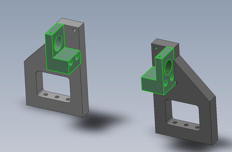
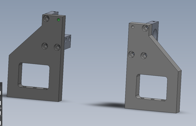
Étape 3 - Assemble damper stop housings
Use 6 off M8 x 30 socket caps to fix
D0007455 Stop Damper Housing OH to D0007454 Stop Sub Base OH
D0008378 Stop Damper Housing to D0008377 Stop Sub Base
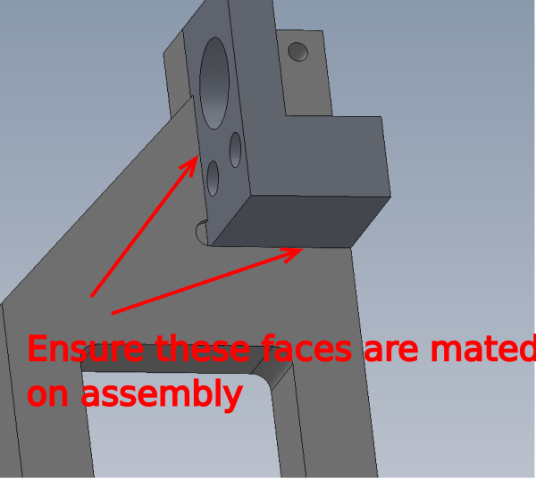
Ensure indicated faces are mated together on assembly
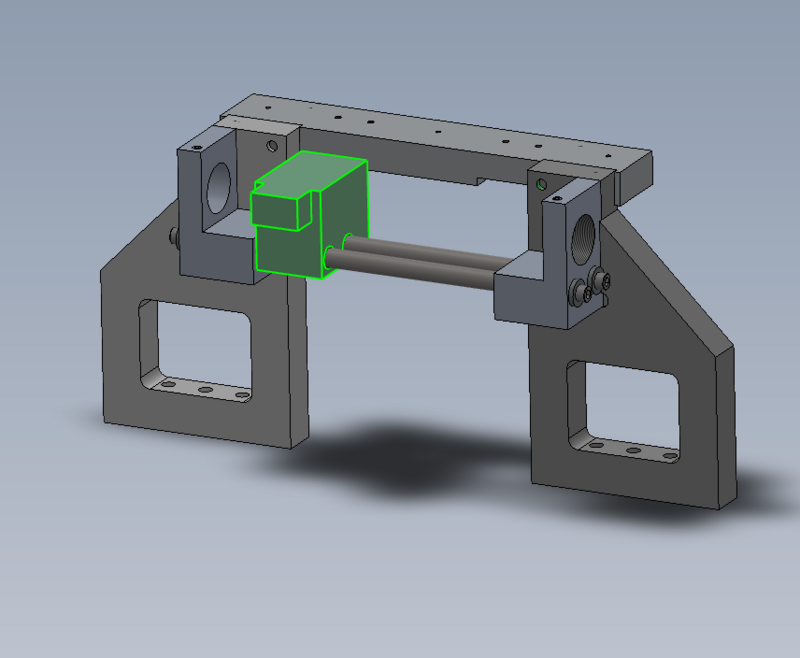
Étape 4 - Insert shafts and slide finger
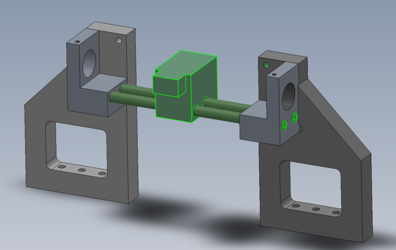
Assemble as shown 2 off H0008379 Shaft 12mm: 263mm R Axis Limit Stainless x 2 and pre assembled slide finger block
Do not add fixings yet
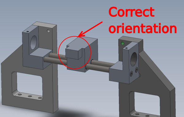
Ensure slide finger is orientated the correct way
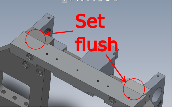
Étape 5 - Fit Cross joiner
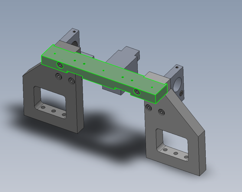
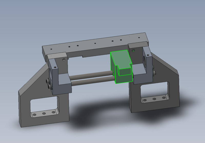
Use 2 off M8 x 50 socket caps to fit D0008383 Cross Joiner as shown
Ensure indicated faces are set flush
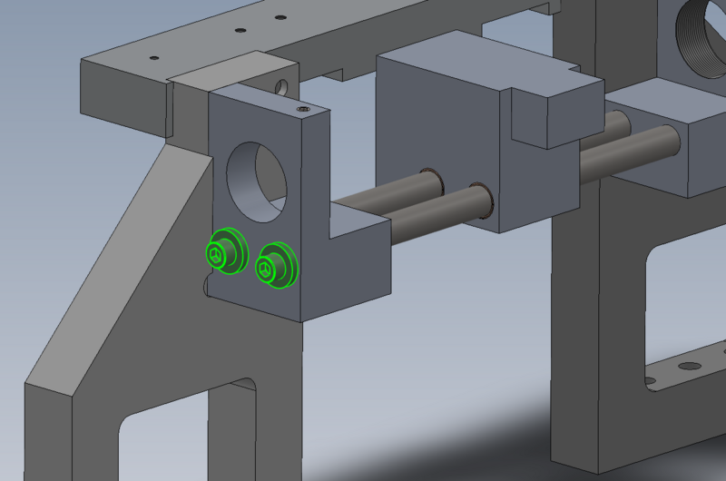
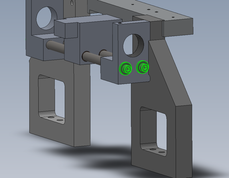
Étape 6 - Fix shafts
Use 4 off M6 x 16 socket caps and heavy M6 washers to fix shafts as shown
Note, slight shaft float will be present, this is normal
Étape 9 - Damper setting
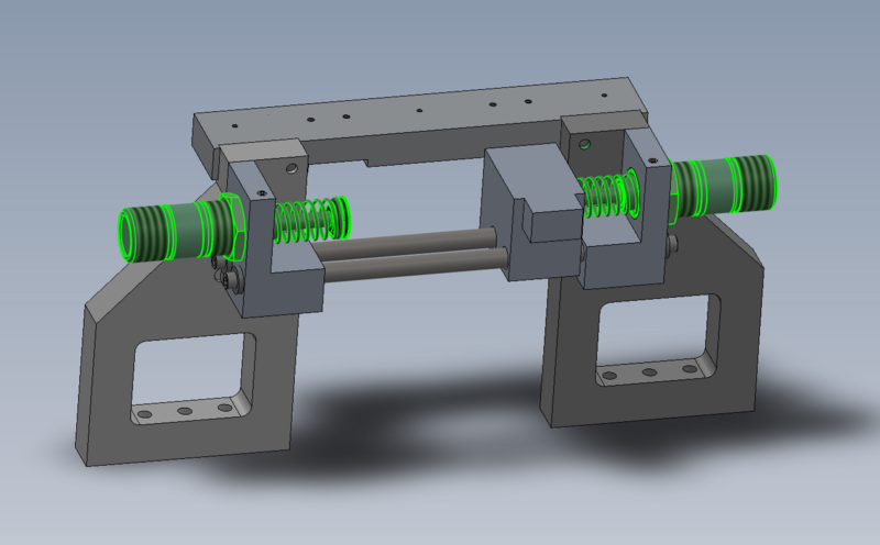
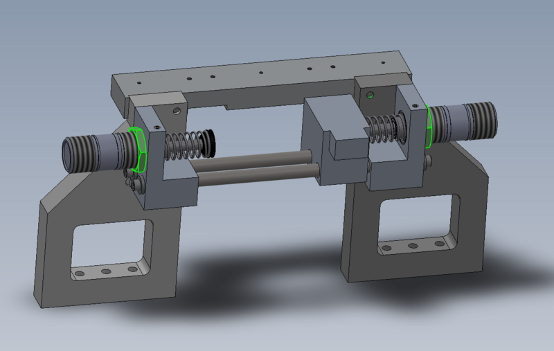
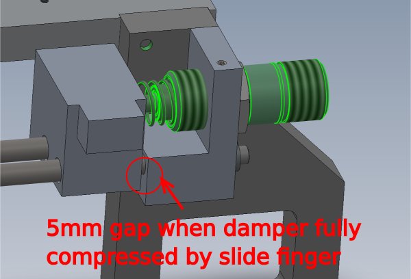
Set dampers to the following spec
With damper fully compressed, a 5mm gap should be present at the indicated point
Set both sides to the same setting
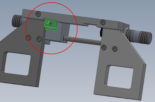
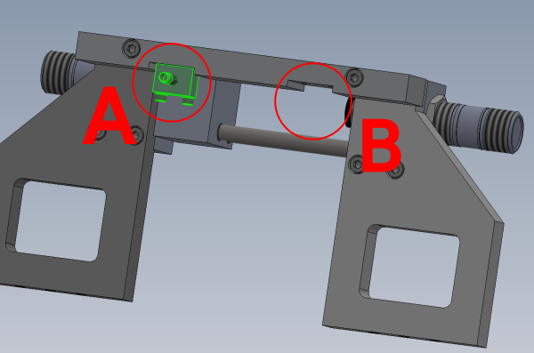
Étape 10 - Fix datum sensor block
Orientation
For R-L machines fit to point A
For L-R machines fit to point B
Use 2 off M5 x 40 socket caps with A form washers to secure D0010756 Proximity Switch Mounting Block as shown
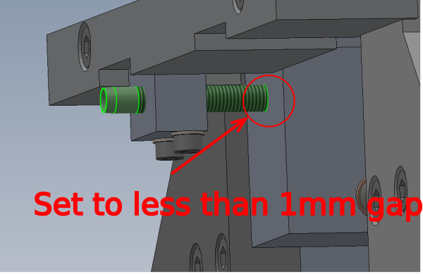
Étape 11 - Set Sensor
Adjust sensor to read indicated face.
Set gap to -1mm
Ensure sensor lock nut is not over tighten when finalising
Draft


 Français
 English
 Deutsch
 Español
 Italiano
 Português