Installation criteria for V notch sub frame
Sommaire
- 1 Introduction
- 2 Étape 1 - Unless otherwise stated
- 3 Étape 2 - Install top Mount
- 4 Étape 3 - Level top mount
- 5 Étape 4 - Fit shafts
- 6 Étape 5 - Caution
- 7 Étape 6 - Add top bearing block
- 8 Étape 7 - Fit rear lower bearing block
- 9 Étape 8 - Fit front lower bearing block
- 10 Étape 9 - Position Bottom support
- 11 Étape 10 - Drop outer shafts
- 12 Étape 11 - Add top washers
- 13 Étape 12 - Drop inner shafts
- 14 Étape 13 - Position bearing assemblies
- 15 Étape 14 - Fit vertical spacers
- 16 Étape 15 - Add lower fixings
- 17 Étape 16 - Add upper fixings
- 18 Commentaires
Introduction
Tools Required
Standard hex key set
Standard Spanner set
Parallel setting blocks
600mm rule
1 meter straight edge
2 meter straight edge
12 " engineers level
12" engineers square
Parts Required
D0015151 Shaft End Washer x 8
D0015155 Vertical Spacer Bar x 4
D0015150 shaft 40mm zx v notch x 4
D0015169B cylinder rod bracket x 2
R0015035 Bench Assemble V Notch ComponentsÉtape 1 - Unless otherwise stated
Use locktite 243 on all fasteners
Use loctite 572 on all threaded pneumatic connection
Pen mark all fasteners to show finalised
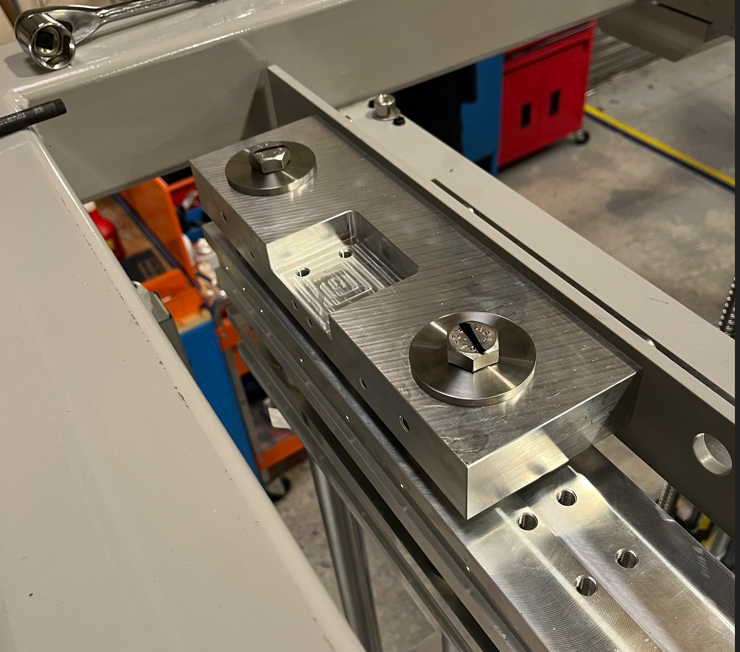
Étape 2 - Install top Mount
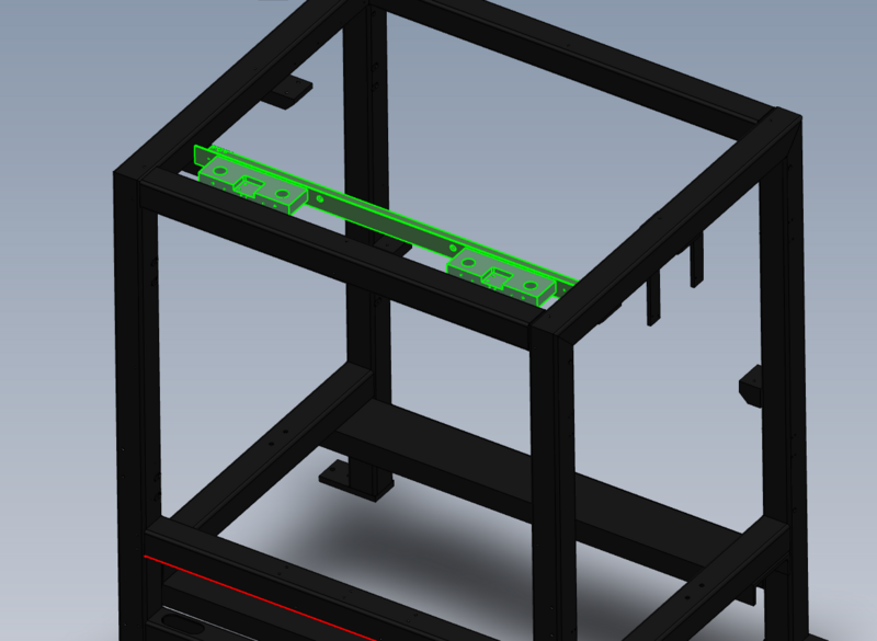
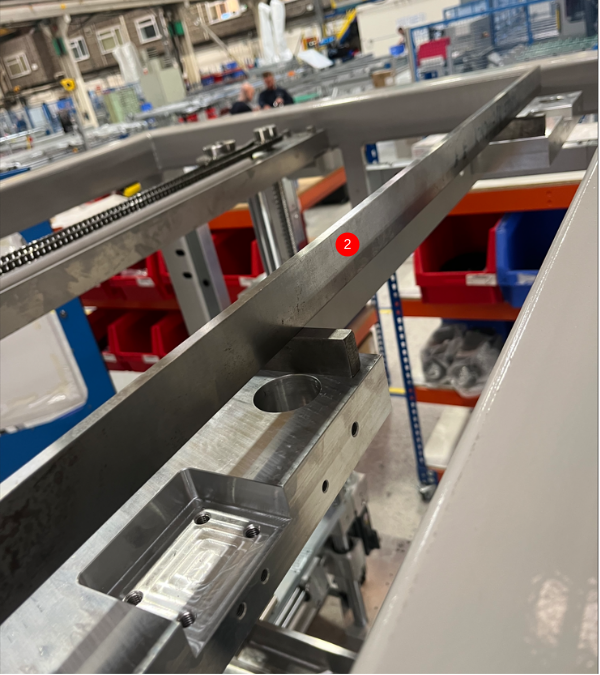
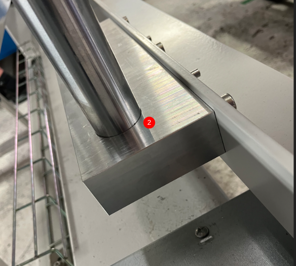
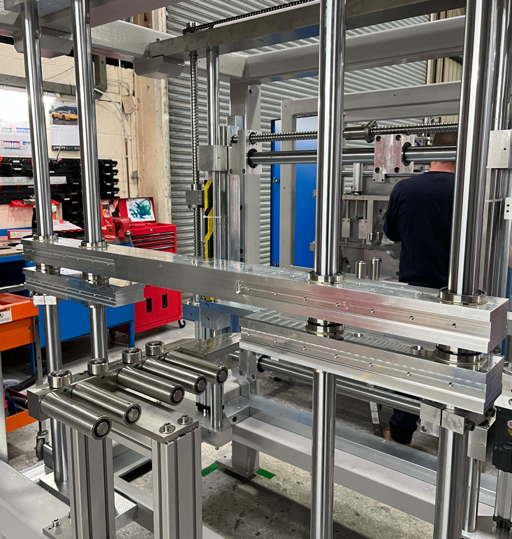
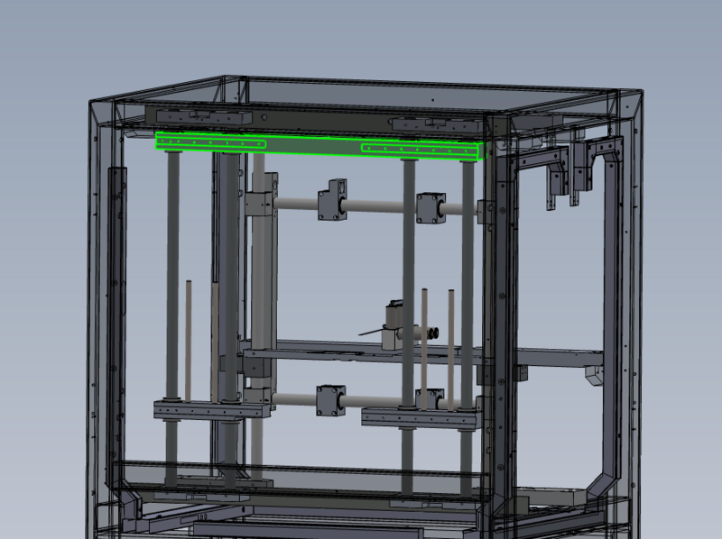
Position top mount as shown
1 Use 4 off M12 x 25 socket caps and A form washers to lightly fix in position
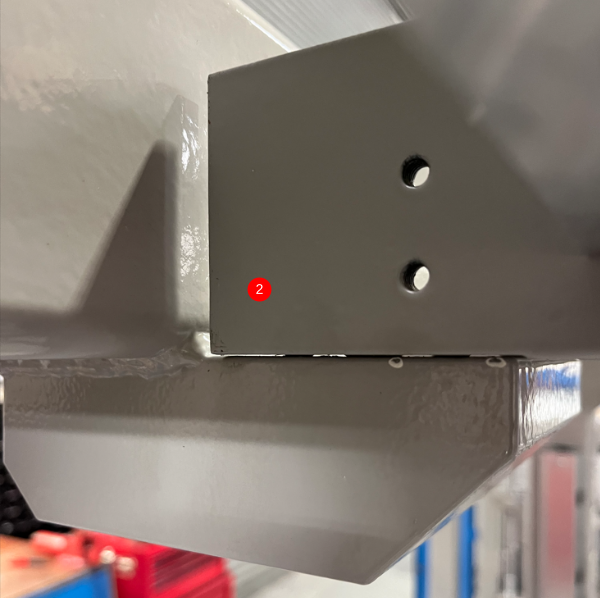
2 Adjust 8 off M10 grubscrews to lift mount approximately 1mm from face of mounting block
Étape 3 - Level top mount
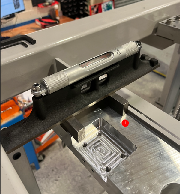
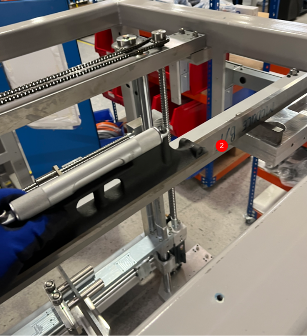
1 Level X axis on both ends as shown using parallels and engineers level , Use M10 grubscrews to adjust
2 Level Y axis as shown , using 1 meter straight edge and parallels. Use M10 grubscrews to adjust
3 Ensure M12 socket caps are tight and recheck levels once set
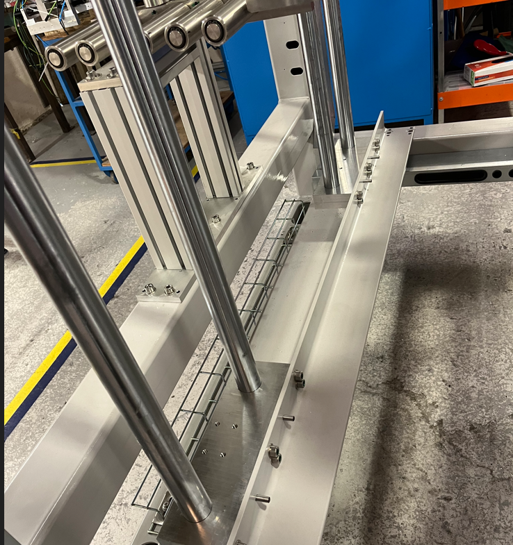
Étape 4 - Fit shafts
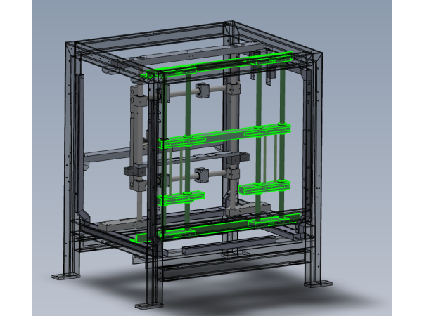
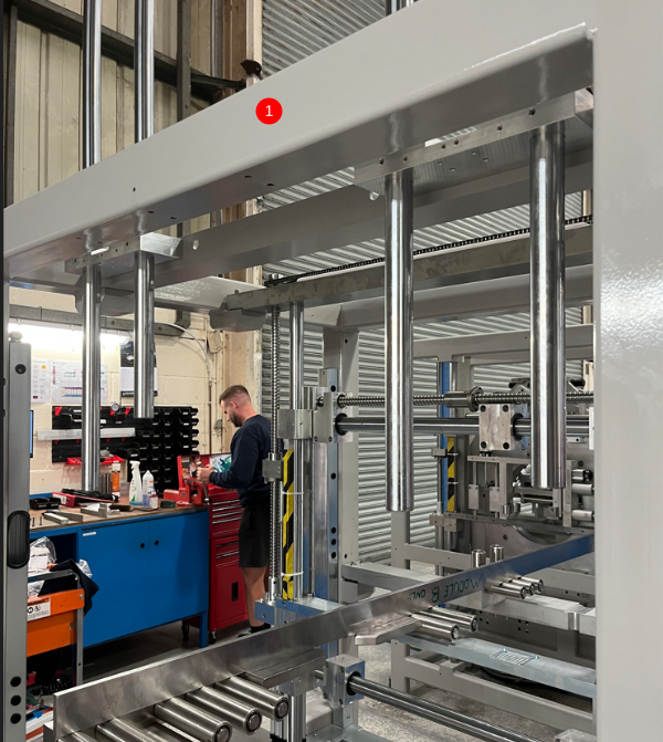
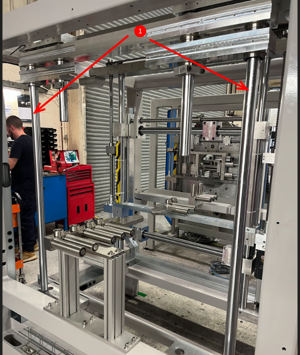
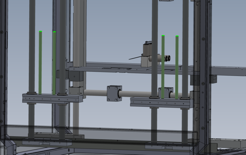
1 Fit 4 off D0015150 shaft 40mm zx v notch as shown , shafts must be staggered as shown
2 Captivate in position with M8 x 12 flat grubscrews in top mount blocks
Étape 5 - Caution
When fitting bearing assemblies, great care should be taken to preserve bearing seals.
Ensure seals are not damaged by folding or kinking during installation
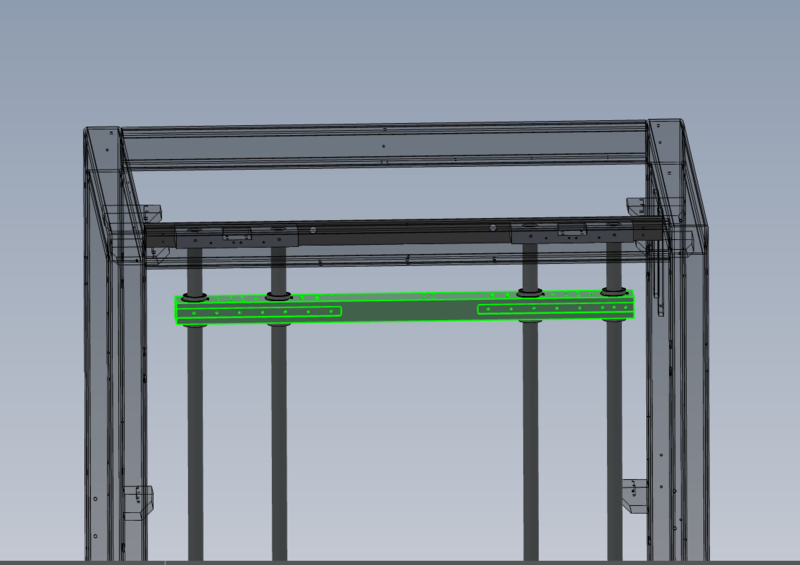
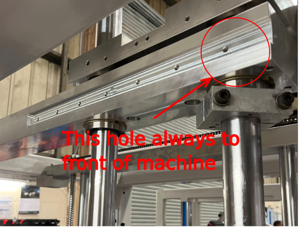
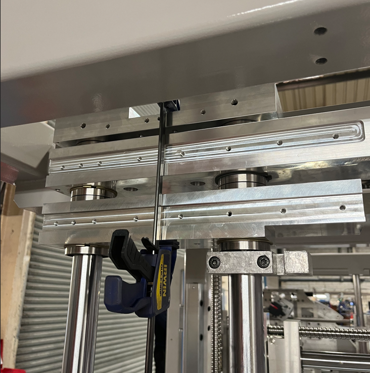
Étape 6 - Add top bearing block
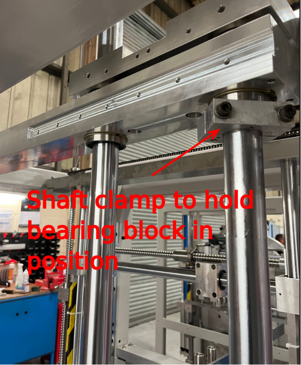
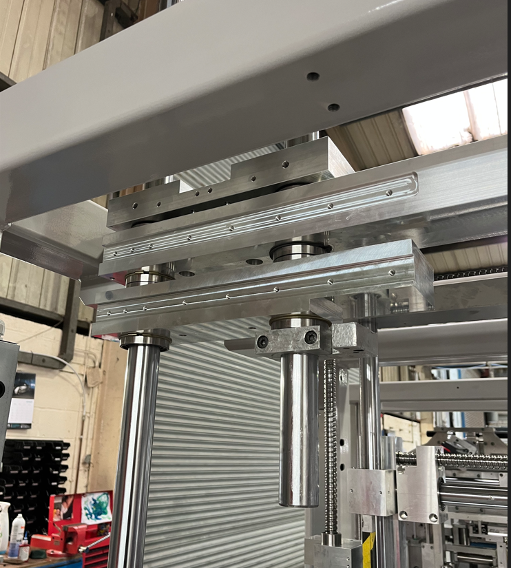
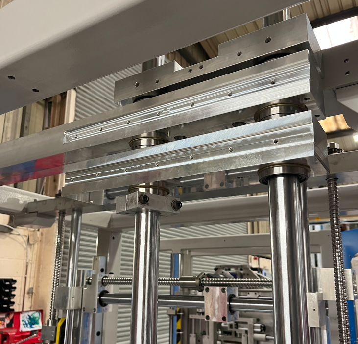
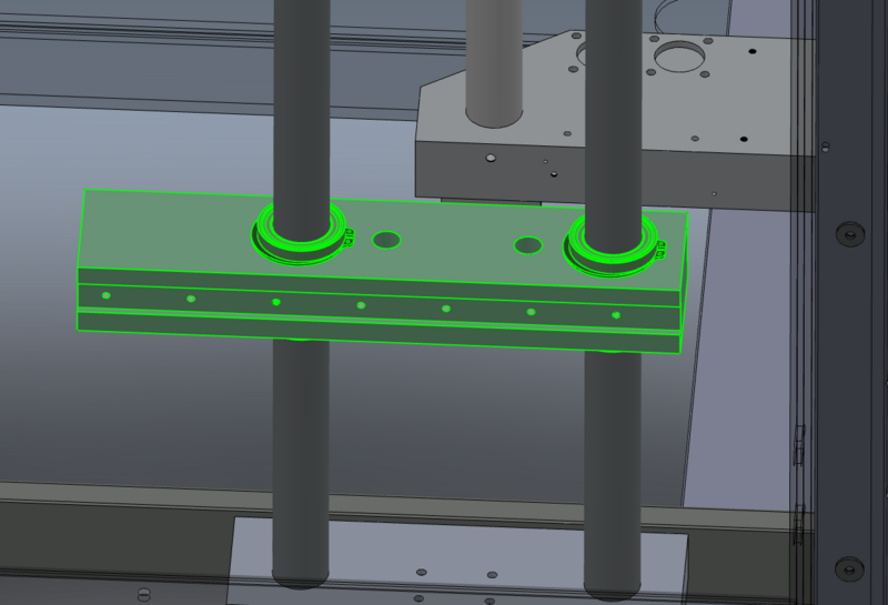
Fit top bearing block as shown.
See photos for orientation
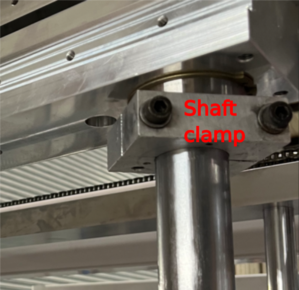
Fit shaft clamp to 1 off shaft to hold bearing block in position
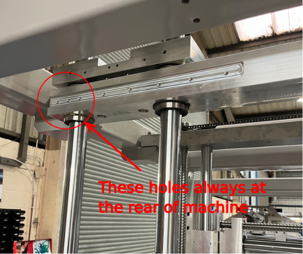
Étape 7 - Fit rear lower bearing block
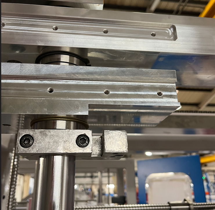
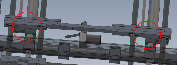
Fit lower bearing block as shown to rear of frame
Take care to orientate correct way
Identify by cut out indicated
Secure with Shaft clamp as shown
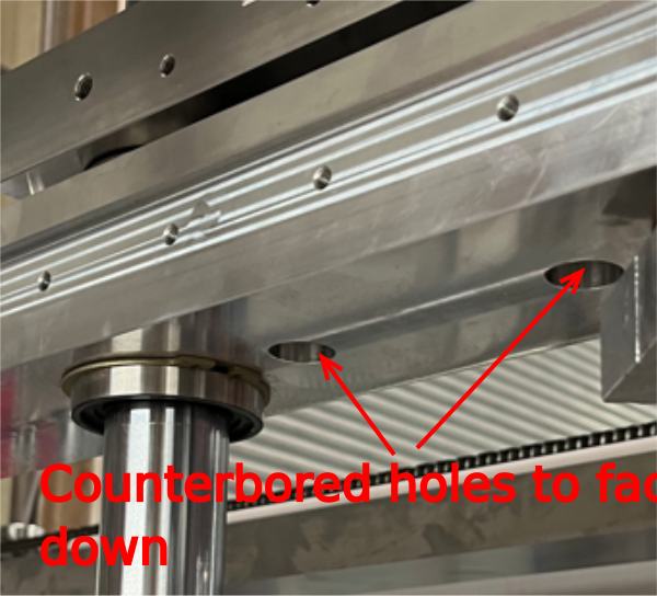
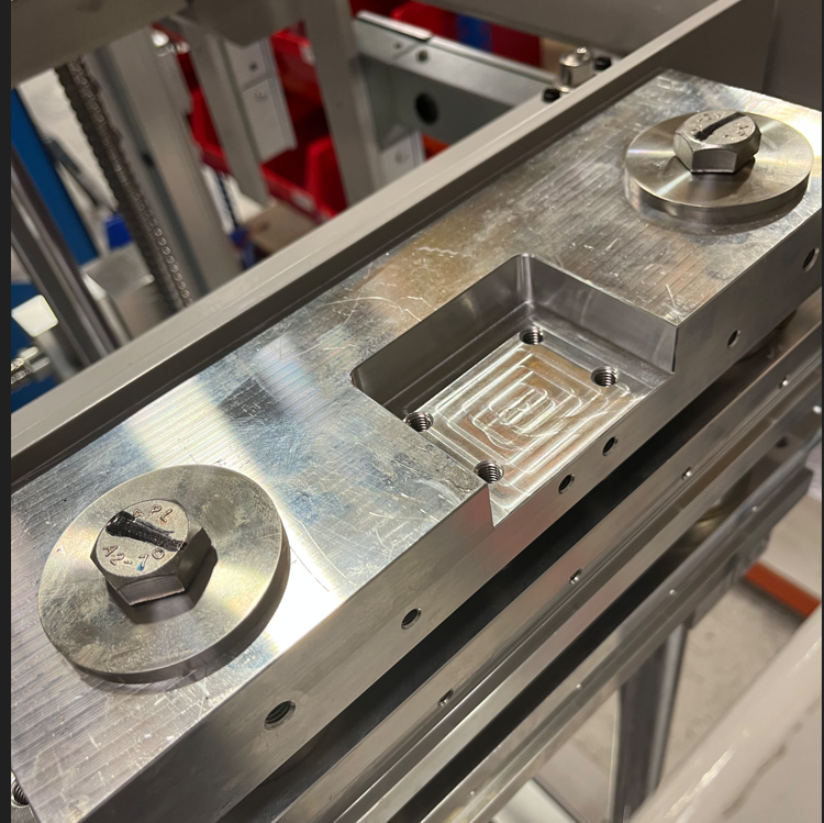
Étape 8 - Fit front lower bearing block
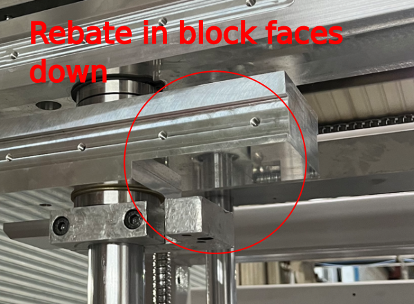
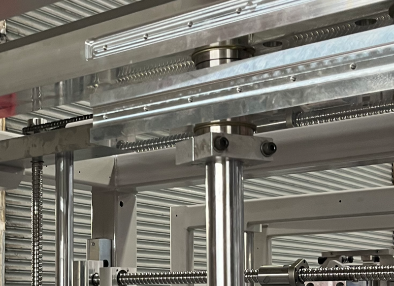
Fit front lower bearing block as shown
Ensure correct orientation
Use counter bores holes as reference, these should be facing up
Secure with shaft clamp
Étape 10 - Drop outer shafts
1 Individually drop 2 outer shafts
Release locking M8 grubscrew to allow movement
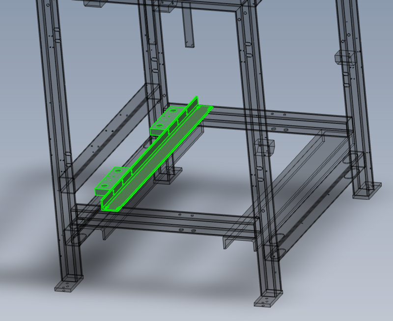
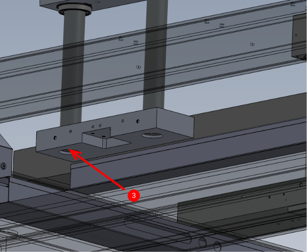
2 Position shafts just above bottom support as shown
Étape 11 - Add top washers
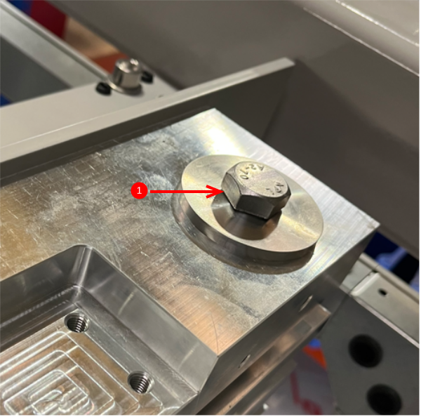
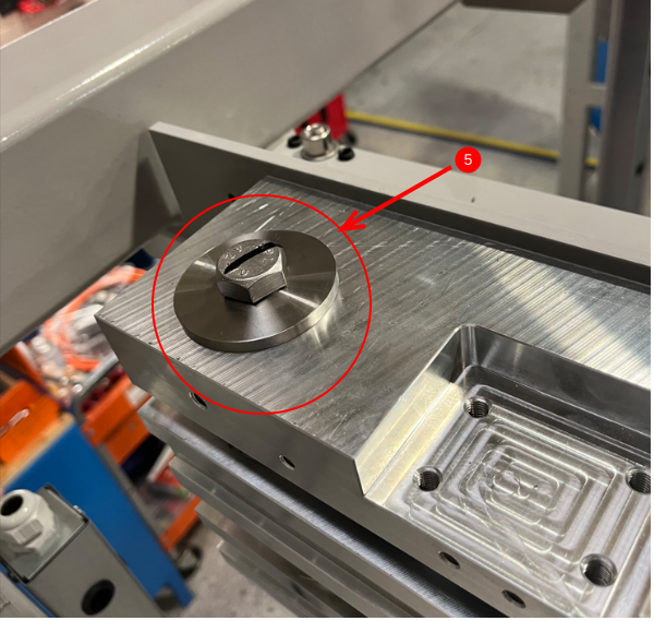
1 Fit 2 off D0015151 Shaft End Washer to outer shafts. Use M16 x 2.0 x 30 set bolt to secure
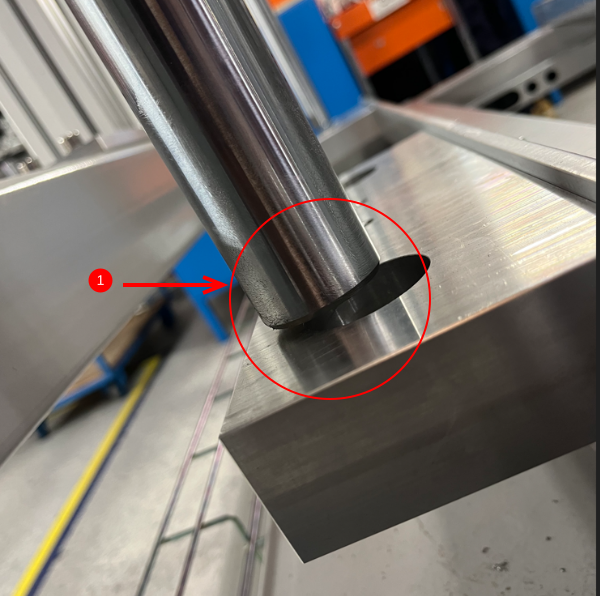
2 Drop outer shafts individually to start penetrating the bores of the lower support blocks (by approx 5mm )
3 Fit 2 off D0015151 Shaft End Washer with M16 x 2.0 x 50 set bolts to shaft bottom
4 Use set bolts to evenly pull lower blocks onto outer shafts
5 Adjust shafts down from top fixing so washers now sit flush to mounting block
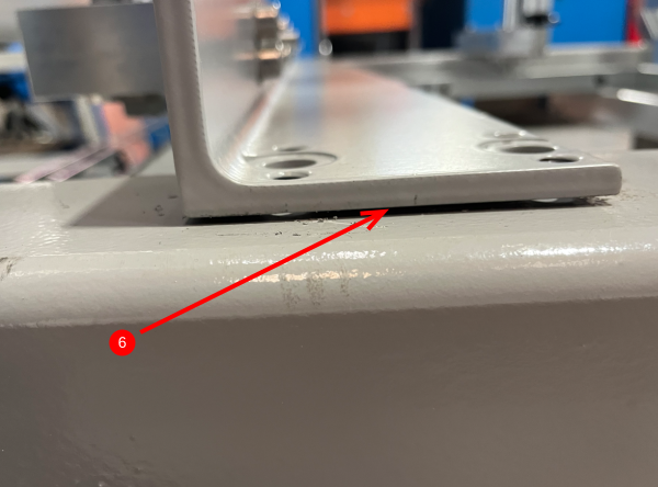
6 Swap bottom outer shaft fixing M16 x 2.0 x 50 For M16 x 2.0 x 30 set bolt and position block as shown (slight gap between support angle and main frame)
Étape 12 - Drop inner shafts
Individually swap shaft clamps to outer shafts (use clamp to hold bearing block when removing shaft clamp )
Repeat step 11 to position inner shafts
Étape 13 - Position bearing assemblies
Reposition bearing assemblies as shown
1 Drop lower rear bearing block by releasing shaft clamp and dropping to shown position
2 Add clamp to hold top bearing block to upper mount
3 Drop front lower bearing block to same height as rear lower and secure with shaft tie
4 Drop upper bearing block to position shown
Étape 14 - Fit vertical spacers
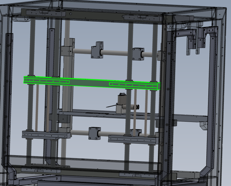
1 Lift upper bearing assembly
2 Position 4 off D0015155 Vertical Spacer Bar as shown
3 Drop upper bearing assembly onto fitted spacers
Étape 15 - Add lower fixings
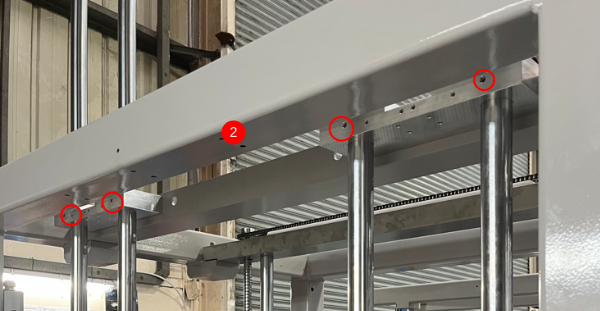
Use 4 off M8 x 50 socket caps with M8 A form washers to fix spacer shafts at positions shown
Étape 16 - Add upper fixings
Draft


 Français
 English
 Deutsch
 Español
 Italiano
 Português