Installation criteria for V notch sub frame
Introduction
Tools Required
Standard hex key set
Standard Spanner set
Parallel setting blocks
600mm rule
1 meter straight edge
2 meter straight edge
12 " engineers level
12" engineers square
Parts Required
D0015151 Shaft End Washer x 8
D0015155 Vertical Spacer Bar x 4
D0015150 shaft 40mm zx v notch x 4
R0015035 Bench Assemble V Notch ComponentsÉtape 1 - Unless otherwise stated
Use locktite 243 on all fasteners
Use loctite 572 on all threaded pneumatic connection
Pen mark all fasteners to show finalised
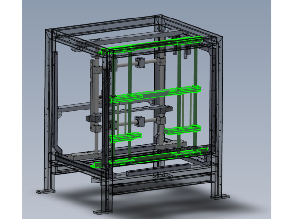
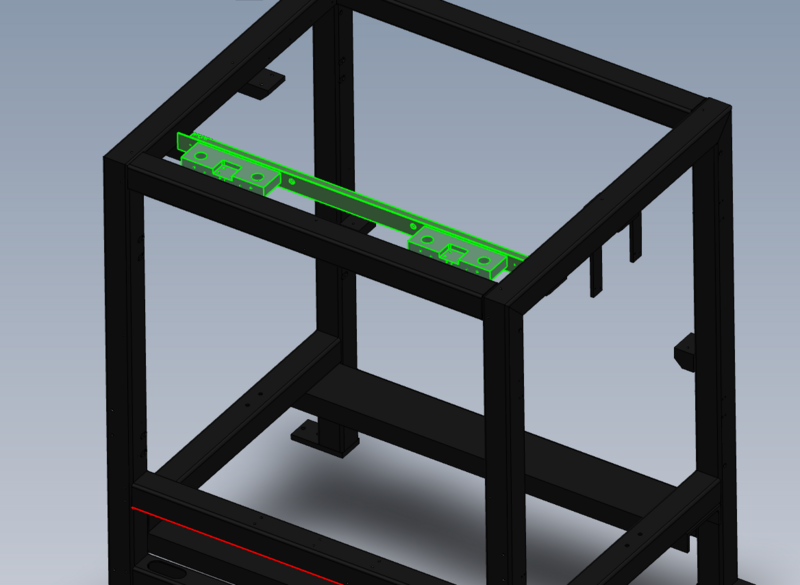
Étape 2 - Install top Mount
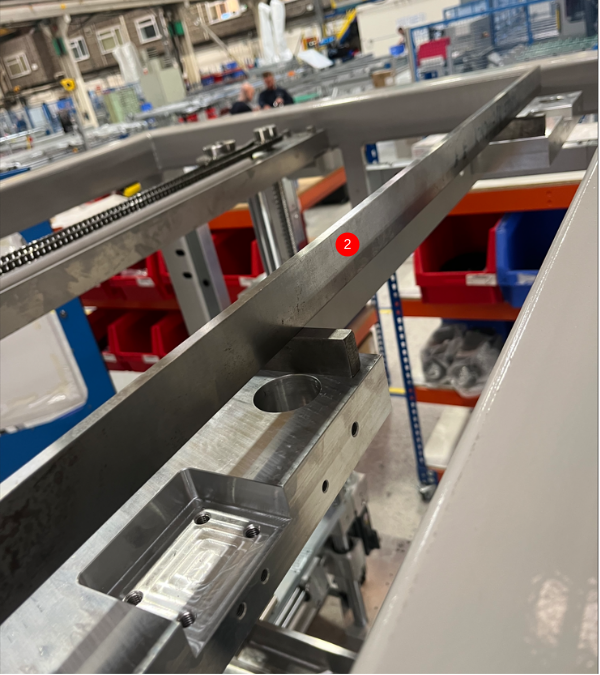
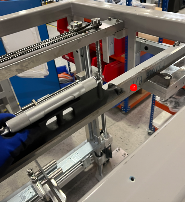
Position top mount as shown
1 Use 4 off M12 x 25 socket caps and A form washers to lightly fix in position
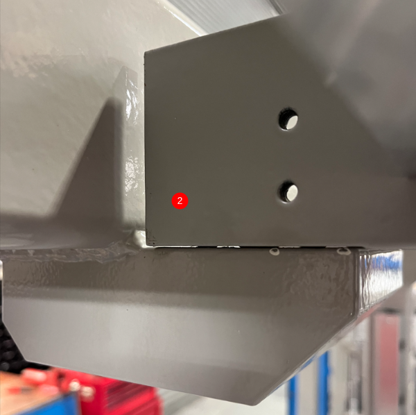
2 Adjust 8 off M10 grubscrews to lift mount approximately 1mm from face of mounting block
Étape 3 - Level top mount
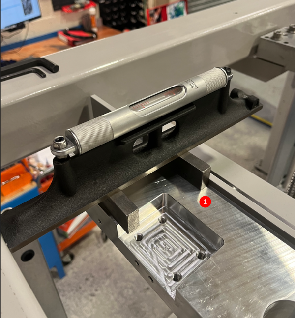
1 Level X axis on both ends as shown using parallels and engineers level , Use M10 grubscrews to adjust
2 Level Y axis as shown , using 1 meter straight edge and parallels. Use M10 grubscrews to adjust
3 Ensure M12 socket caps are tight and recheck levels once set
Étape 4 - Fit shafts
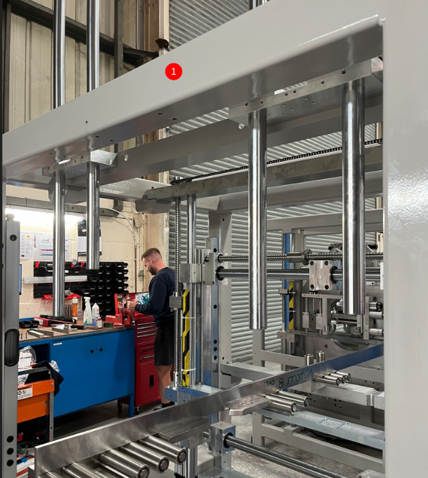
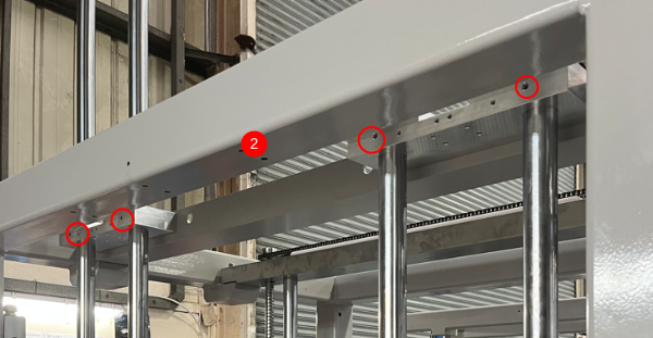
1 Fit 4 off D0015150 shaft 40mm zx v notch as shown , shafts must be staggered as shown
2 Captivate in position with M8 x 12 flat grubscrews in top mount blocks
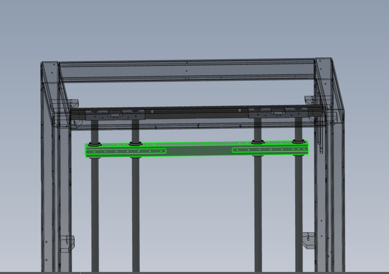
Étape 5 - Add top bearing block
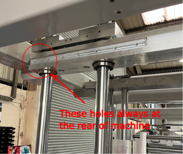
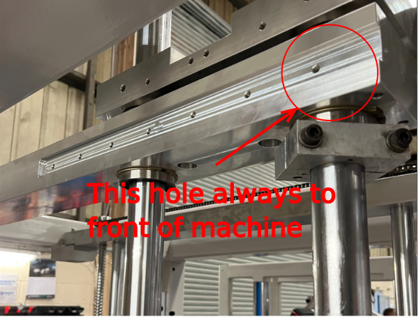
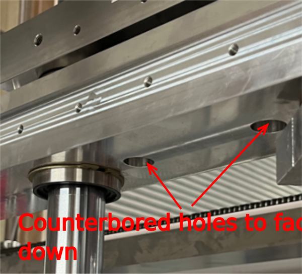
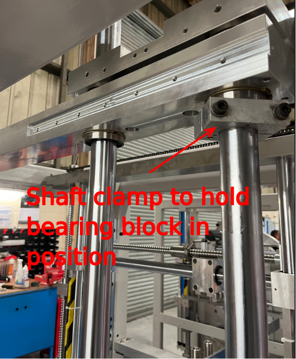
Fit top bearing block as shown.
See photos for orientation
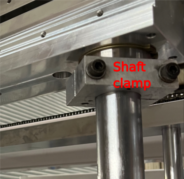
Fit shaft clamp to 1 off shaft to hold bearing block in position
Draft

 Français
 English
 Deutsch
 Español
 Italiano
 Português