| [version en cours de rédaction] | [version en cours de rédaction] |
| Ligne 37 : | Ligne 37 : | ||
{{Tuto Step | {{Tuto Step | ||
|Step_Title=<translate></translate> | |Step_Title=<translate></translate> | ||
| − | |Step_Content=<translate>The | + | |Step_Content=<translate>The Protection plate screw holes can be used as a Guide to get the receiver aligned at the right height when the cover is off. Undo the locknuts on Receiver and move up/down as required Keeping the Lens Square to the Laser at all times.</translate> |
| − | |Step_Picture_00= | + | |Step_Picture_00=Laser_setup_LS3.jpg |
}} | }} | ||
{{Tuto Step | {{Tuto Step | ||
|Step_Title=<translate></translate> | |Step_Title=<translate></translate> | ||
| − | |Step_Content=<translate>The | + | |Step_Content=<translate>The laser receiver needs to be as square and as close to the center of the aluminium deflection plate</translate> |
| − | + | |Step_Picture_00=Laser_setup_LS2.jpg | |
| − | |||
| − | |Step_Picture_00= | ||
}} | }} | ||
{{Tuto Step | {{Tuto Step | ||
Version du 26 mars 2020 à 12:19
Laser Setup on Flowline/ZX3

Difficulté
Moyen
Durée
30 minute(s)
Introduction
How to Setup .
This will Cover the Basic Alignment of the receiver and Sender setup.
Focusing the Laser and Setting up the Receiver Sensitivity.
- Pièces et outils
Pièces et outils
Laser Focusing Spanner 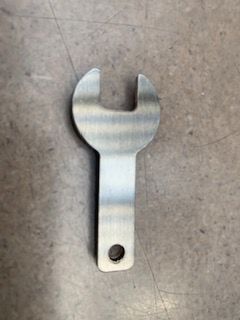

9mm spanner supplied with B0000360
Spanner 24mm 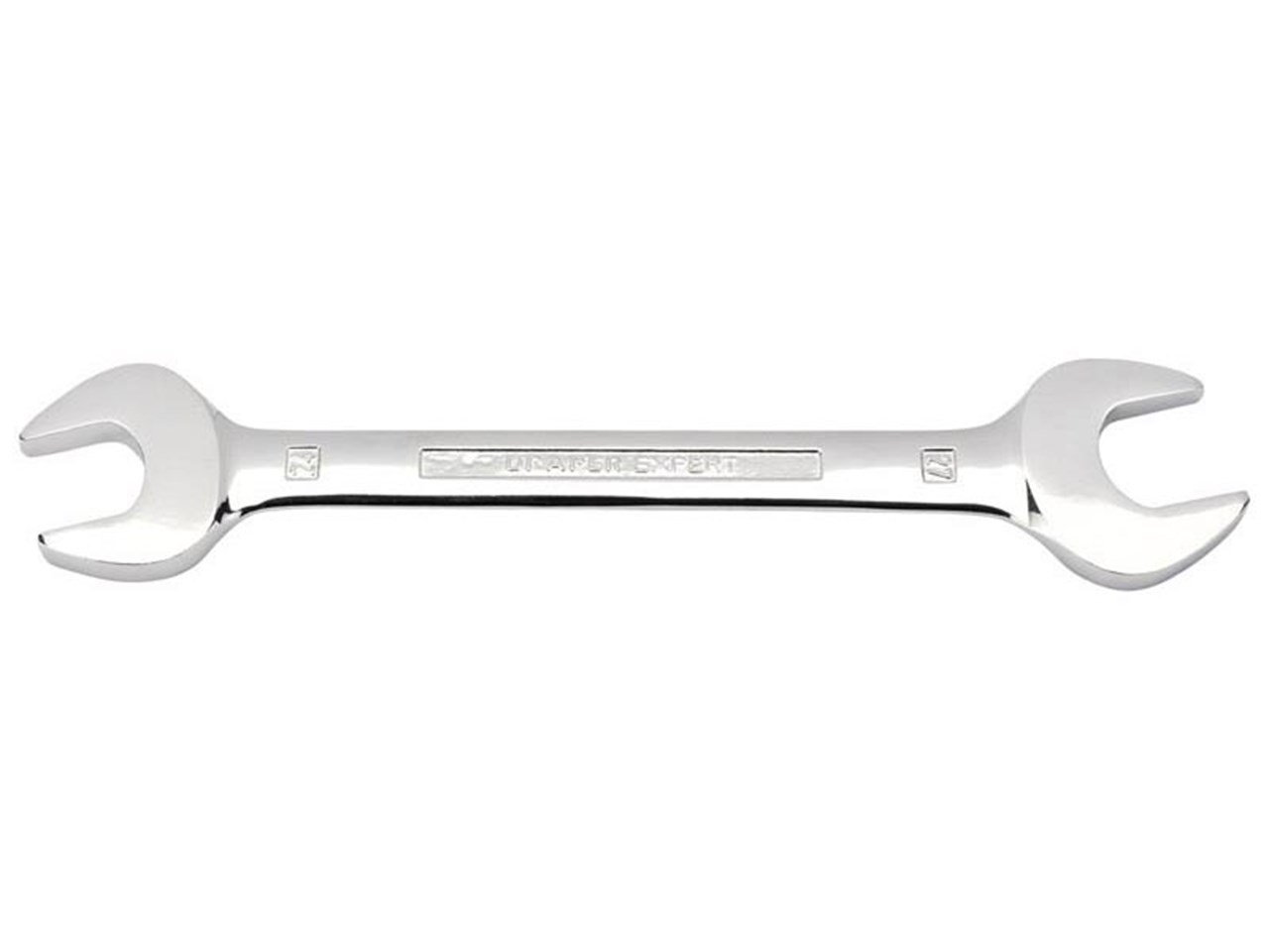

Open ended spanner 24mm
Spanner 24mm
Open ended spanner 24mm
Étape 1 -
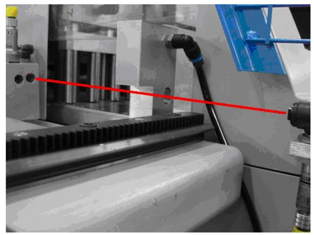
The laser sender needs to have a clear path to the laser receiver, its really important that this is parallel and the beam does not bounce off the inside of any of the aluminium mounting block. Slacken off the Nuts above and below Laser to move up/down and side/side.

Étape 2 -
The Protection plate screw holes can be used as a Guide to get the receiver aligned at the right height when the cover is off. Undo the locknuts on Receiver and move up/down as required Keeping the Lens Square to the Laser at all times.

Étape 3 -
The laser receiver needs to be as square and as close to the center of the aluminium deflection plate

Étape 4 -
Once you are happy that the laser sender and receiver are clean, parallel and you have no deflections place a profile label over the receiver hole and check you have a clear point to the laser and not a large spot with undefined edges.

Étape 5 -
The laser clarity can be adjusted using the spanner supplied, keep turning Clockwise or Anticlockwise until a Very Clear Red Dot of approx 1mm Diameter is shown on Paper in front of receiver hole.

Étape 6 -
Finally the laser receiver sensitivity needs to be checked. Unscrew the adjusting screw (AntiClockwise) until the GREEN Led goes RED. .
Then turn screw (Clockwise) until RED Led goes back to GREEN then turn a further 5 full turns the same way, the receiver sensitivity is now set

Étape 7 -
As for software there are a few more things to think about.
- Multihead
- Z axis position of the Laser Hole files.
- Laser Holes getting done as slots for bent profiles.
- Speed control to keep slots/holes Clean.
- Saw
- Good Drive tuning, need following error of +/- 0.1mm on speed of 300mm/sec
- Laser hole Size Parameter - Should be 10mm
- Laser hole Tolerance should be no more than 1.2 (10-1.2=8.8mm)
- Drive speeds/Acceleration/Deceleration,etc
- Blower for Laser holes.
Draft
 Français
 English
 Deutsch
 Español
 Italiano
 Português